by Danny Stewart
Having established some internationally recognized standard units of measurement in Part 1 of this series, we shall now take a look at some actual practical methods of measuring electrical properties.
Wheatstone Bridge
A basic bridge circuit is shown in Figure 1, where D is a detector, usually a galvanometer or any other sensitive current meter. The bridge is balanced when the voltage across the detector is zero volts and there is no current flowing through it. This can be expressed as:
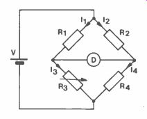
Figure 1. Basic Bridge.
Equation 1.
I,R, = 12R2
And if no current flows through the detector, then it must flow through the resistance dividers making 11 = 13 and 12 = 14, also:
Equation 2.
1, = V RI + R3 and Equation 3.
12 = V R2 + R4
Substituting for I, and 12 in Equation 1 gives:
Equation 4 R1 = R2 R, + R3 R2 + R4
Simplifying Equation 4 gives Equation 5:
111114 = R2R3
In general, if the arms of the bridge are not pure resistances then:
Z1Z4 = Z2Z3
R1 and R2 are ratio arms and are switchable from fractions of an ohm to several megohms.
R3 is a precision standard which is also selectable. This leaves R4 as the unknown resistor and from Equation 5, Equation 6:
R4 R3R2 R1
Although this example illustrates the use of a bridge for measuring resistance, inductors and capacitors can also be measured.
Indirectly, frequency and phase angle can also be measured.
Since the bridge method compares the unknown against a fixed standard, this is a highly accurate method. Also the measurements are independent of the characteristics of the null detector as long as the detector can detect a null with a reasonable degree of sensitivity.
Therefore any lack of accuracy will be attributed to tolerance of the three resistors and any heating effect of the current through the resistors, particularly for low values of resistance. Inaccuracy can also be due to an insensitive null detector. In spite of all this, the basic Wheatstone Bridge is used to measure resistors from one ohm to one Megohm.
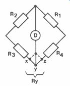
Figure 2. Measuring Resistor Values below 10.
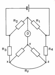
Figure 3. Kelvin Double Bridge.
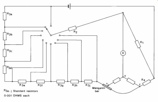
Figure 4. Stepped Resistors.
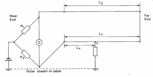
Figure 5. Murrary Loop Test.
Kelvin Bridge
To measure resistor values below 1 ohm requires a modification to the basic Wheatstone Bridge. Figure 2 shows the problem. The resistance of the leads become significant in measuring the unknown resistance.
Connecting the detector to either x or z means increasing the resistance in the respective bridge arms. But if the detector is connected to pointy such that:
Rxy = Ryz R2 R then the bridge balance conditions are met and:
R4 = R1 R3 R2
where R4 could be the unknown resistor.
Figure 3 shows a Kelvin double bridge, so called because it contains an additional pair of ratio arms to eliminate the effect of wire xz. As before:
Rxy = R2 Ryz R1
The Kelvin Bridge can be used to measure resistors down to 0.00001 ohm. If R3 is the standard resistor then it could be arranged in steps of 0.001 ohm, as shown in Figure 4. A manganin bar of 0.0011 ohm provides a sliding contact for small adjustments and for good accuracy as much of the standard resistance must be included in the circuit. This depends on the ratio of R1 to R2. As for the Wheatstone Bridge, R1 and R2 are switchable in decade steps.
Murrary Loop Test
A modified form of the Wheatstone Bridge is used to detect wires shorting to earth in a telephone cable.
If a wire is shorting to earth at point x, Figure 5, it is connected to a good wire at the far end and both wires connected to a Wheatstone Bridge. In this way both wires will contribute towards two arms of the bridge, with point x the dividing point. The balance condition is given by:
R1 = RL - Rx R2 Rx where RL is the total resistance of the two wires, Rx is the resistance from the bridge to point x.
Therefore, Rx = R2 RL R1 + R2 length is proportional to resistance, so we can replace Rx and RL above.
Lx = R2 (L1 + L2) R1 + R2
Also L1 = L2
Hence Lx = R2 2L R1 + R2 and the distance to the faulty point can be calculated.
Valley Loop Test
This is a further modification of the Wheatstone Bridge and is also used to detect cable faults, e.g. crossed connections, short circuits or earth faults. This test is usually used to locate a fault down to a cable section and is capable of locating within 500 feet in a 50 mile section. The Murrary test can then be used to locate within the section, therefore the Murrary test set is usually of the portable variety, employing batteries.
The Varley test is a more complex test than the Murrary test and employs three wires with different connection arrangements, see Figure 6a, b, c.
Compared to the Murrary Bridge, the Varley has resistors in three arms instead of two and the variable resistor is placed in the third arm. The ratio arms R1 and R2 are varied by a dial to give a ratio from 0.001 to 1,000 in decade steps.
Analysis of the circuits in Figure 5 yield:
= R1 (B-A) R1 + R2 (L1 Lx)
= R1 (C+B) R1 + R2
Substituting the results of the measurements in the above two equations gives the distance to the fault. It can be seen that one equation provides a check on the other.
A. C. Bridges
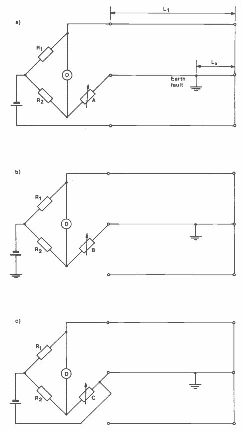
Figure 6. Varley Loop Test.
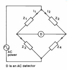
Figure 7. A.C. Bridge.
An a.c. bridge will require an a.c. power source and an a.c. detector, and is used for measuring inductors , capacitors, frequency, i.e. anything other than resistance which is the domain of d.c. bridges.
An a.c. bridge then, will have the general format of Figure 7, where the Z values are capacitors or inductors with their associated resistive components. the detector can be a pair of headphones or magic eye (electron ray tube).
At low frequencies, the domestic mains supply is an adequate source but at higher frequencies an oscillator must be used at the frequency for which the component is designed.
For bridge balance, the potential difference across the detector has to be zero, as for d.c. bridges. This will occur when the potential difference across Z, is the same as that across Z2 in both magnitude and phase.
i.e. I1Z1 = 12Z2 also I, = V Z1 + Z3 and 12 = V Z2 + z4
Substituting for II and 12 gives:
Z1Z4 = Z2Z3 or using admittances Y1 Y4 = Y2Y3
In complex rotation, the magnitudes are multiplied and the phases angles added:
Z1Z4 / (01 + 04) = Z2Z3 / (02 + 03) and for balance, not only must Z14 = Z2Z3 but / (91 + 04) must equal (02 + 03).
Capacitance Bridge
Figure 8 shows a bridge arrangement for measuring capacitance where Cx is the unknown capacitor and Rx its associated leakage resistance. These two components are reflected on the other side of the equation by standard capacitor Cs and a variable resistor Rs.
Now Z1 = R1, Z2 =
Z3 = Rs - , Z4 = RX -
WCs
Substituting in Z1 Z3 = Z2Z4 R1 Ax - wCx = R2 ( wCx Rs -j WCs R1Rx - R1 = R2RS R2 wCx wCs
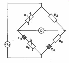
Figure 8. Bridge for Measuring Capacitance.
Such equations are solved by equating real and imaginary expressions separately.
Equating real terms:
R1 Rx = R2Rs
Equation 7.
R2Rs R1 Equating imaginary terms:
jR, = jR2 wCx wCs
Equation 8.
Cx = Cs R1 R2 Cx is a precision standard capacitor that cannot be adjusted and since Rs does not appear in Equation 8, it can be made adjustable. One other variable component is required in order to balance the above two equations. Unfortunately, the choice is between R1 and R2 which appear in both equations.
If R1 is chosen, then R, and Rs need to be changed alternately for minimum sound in the headphones until balance is obtained.
This is called convergence.
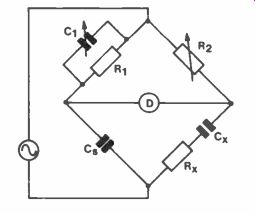
Figure 9. Schering Bridge.
Schering Bridge
Figure 9 shows a Schering Bridge which is one of the popular bridges for measuring capacitors and insulators.
For measuring insulation (phase angle nearly 90°), Cs is an air dielectric capacitor.
Otherwise, Cs is a mica capacitor which also has low loss and therefore, a phase angle of 90°.
Substituting in the balance equation 4
Z3 Rx-j R2 1 +WCI wC2 WCs Rx - j = R2 C, 'R2 XX Cs wCsR,
Equating real terms Rx = R2 C1 Cs
Equating imaginary terms Cx = Cs R, R2 Zx =
Inductance Bridge
The general form of an inductance bridge is shown in Figure 10 where Lx is the unknown inductor and Rx its resistive component. To balance these on the other side of the equation, the standard is in two parts, Ls and Rs.
Circuit analysis yields:
Rx = Rx R2 R, Lx Ls R2 R1
In an inductor, the resistive component is larger than that in a capacitor, so the resistive adjustment must be made first.
When measuring inductors, Q values must be taken into account. The Q of a coil is and the Q of a capacitor.
For Q wCR values above 10, a Hay bridge is used and for between one and ten, a Maxwell bridge is used. The reason for this will become clear below.
Hay Bridge
Figure 11 shows a Hay bridge. The impedances of the arms are:
Z, = R1 - , wC, Z2 = R2, Z3 = R3, Zx = Rx + jwLx.
Substituting in Z1Z0 = Z2Z3 (R1 - j) (Rx + jwLx) = R2R3 wC, R, Rx = jwLxR, + Lx = R2R3 wC, C,
Equation 9.
Equating real terms R, Rx + = R2R3 C1
Equation 10.
Equating imaginary terms wLxR,
= Rx wC,
Equations 9 and 10 each contain both Rx and Lx, therefore these equations need to be solved as simultaneous equations, yielding:
Equation 11.
Rx =
Equation 12.
Lx= wC12R1R2R3 1 + w2C121312 C1R2R3
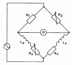
Figure 10. Inductance Bridge.
Substituting Q = 1 in Equation 12:
wCR Equation 13.
Lx C1R2R3 If Q = 10 then (1/0)2 = 0.01 and is insignificant and Equation 13 reduces to:
Lx = C1R2R3.
This final equation is the same as that for a Maxwell bridge, which has a different component arrangement.
Maxwell Bridge
Figure 11. Hay Bridge.
A Maxwell bridge is suitable for coils with a Q between one and ten. Figure 12 shows the arrangement of components in a Maxwell bridge.
Now Z, = R,( 1 ) jwC, R,+ 1 jwC, Ri jwC, = R, jwC, R, + 1 jwC, R, + 1 jwC, Z2 = R2, Z3 = R3, Zx = Rx + jwLx Substituting in Z, Zx = Z2Z3 R, jwC, R, + 1 (Rx + jwLx) = R2R3 Equating real terms:
1 + vi2ci2R12
TEST GEAR & MEASUREMENTS Equation 14.
Rx = R2R3 R, Equating imaginary terms:
Equation 15.
Lx = C, R2R3
Since R3 is common to both Equations 14 and 15, adjustment of R3 to balance the inductor, upsets the resistive balance. Using 11, and R3 in turn results in successive balance points such that convergence is obtained towards final balance.
The other bogey man of bridge circuits is stray capacitance between bridge arms. Up to now we have assumed that the arms of the bridge contain lumped impedances. In practice, stray capacitance couples the various arms and upsets the balance giving a false reading.
One way out of this is the Wagner ground where all the arms are shielded and the screens connected to ground. This does not get rid of the capacitances but does make them constant in value enabling them to be included in the calculation.
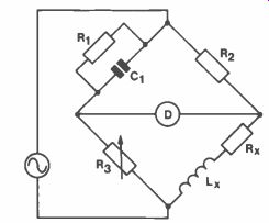
Figure 12. Maxwell Bridge.
Wien Bridge This is a very useful bridge for measuring frequency, Figure 13. One of the drawbacks is that it requires a pure sinusoid, and any harmonics tend to upset the balance.
The Wien bridge is versatile and has been used in modified forms in oscillator circuits as well as notch filters in frequency analyzers for extracting a particular frequency.
Z3 = R3 jwC3R3 + 1 Z2 = R2 Z4 = 134 Zi = Ri + 1 jwC,
Substituting in Z,Z4 = Z2Z3 1 ( + R4 = R2 (jwC3R3R3 1 ) jwC, Ri R4 + R4 = R2R3 jwC, jwC3R3 + 1 R, R4(jwC3R3 + 1) + R4 (jwC3R3 + 1) jwC,
= R2R3 jWC3R3R1 Rs + R, 134 + R4 jwC1
= R2R3
Equating imaginary terms:
w2C3C1 R, R3R4 = R4 W2C3C1 Ri R3 = 1 w2 =
C3Ci R R3 if C, = C3 and R, = R3 then w2 = 1 C2R2 w=
CR Equation 16.
f= 1 2 pi CR
Equating real terms:
R,R4 + R,R4 R4R3C3 C1 R4C3 R3 C1
= R2R3 Ri + C3 = R2 R3 C1 R4
= R2 R4R3C3 C,
As before, if C, = C3 and R1 = R3
Equation 17.
then R2 = 2 R4
This means that if R2 is twice the value of R4, then R, and R3 can be ganged together and altered in equal steps to achieve balance.
Therefore only one control is sufficient, and can be calibrated in frequency according to Equation 16.
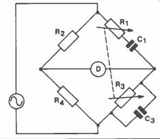
Figure 13. Wien Bridge.
A Universal Bridge
A portable impedance measuring instrument complete with handle and lid is standard in most development laboratories. In order to measure resistance, inductance and capacitance, such an instrument needs d.c. and a.c. power supplies as well as d.c. and a.c. detectors.
For a d.c. power supply, battery packs are used, and a.c. is supplied from an oscillator via RC networks to select the frequency. A frequency of 10kHz is the usual standard.
A suspension galvanometer with a sensitivity of 0.5µA per division is used as a d.c. detector in resistance measurements. An electron ray tube (magic eye) is used as an a.c. detector. There is usually an external facility for connecting headphones, as well as an a.c. mains power supply input.
Now to the actual measurements themselves. What is the minimum number of bridges we can get away with? For inductance measurements, both the Hay and Maxwell bridges are required for Q above ten and less than ten respectively. For resistance measurements a Wheatstone bridge is adequate and a bank of standard capacitors is required for capacitance measurements. So about half a dozen different bridges will serve most requirements.