by J.K. HearneId
Choosing the best type of capacitor for a circuit is not always easy. Manufacturers' data sheets are packed with helpful information like "Insulation resistance >5000 M-ohm", and "Power factor <0.013 at 10kHz", but unless you know what it all means - and why it matters - you might just as well pick the cheapest component with an adequate voltage rating and hope for the best.
If you need a 0.1µF capacitor, for example, the Maplin catalogue gives you twelve to choose from, see Table 1. They range from a tantalum electrolytic the size of a dried pea, right up to a polystyrene component as big as a cigar butt. Why are there so many different types? The answer, of course, is that each has been carefully optimized for one of the many different roles capacitors have to fill - coupling in audio circuits, interference suppression, tuning RF oscillators, decoupling digital logic circuits, and so on.
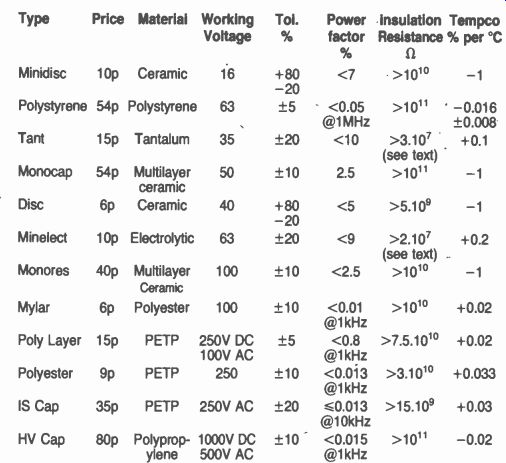
Table 1. 0.1 uF capacitors summary.
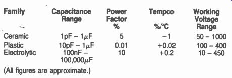
Table 2. The three main families of capacitor.
Value
Capacitors are generally sold as preferred values in the range from 1pF to about 10,000µF. The lower limit is set by the inevitable stray capacitance around the component when it is used, and at the upper end of the range the components can store so much energy for such long periods that they are virtually batteries.
Indeed, a 1 Farad capacitor is made especially to act as a short-term emergency power supply for computer memory boards.
The range of preferred values in each decade are often just 1, 1.5, 2.2, 3.3, 4.7, and (sometimes) 6.8, with a tolerance of typically 10%. This rather limited range is not always as restricting as it seems; after all, it doesn't really matter if the value of a decoupling capacitor is slightly higher than it need be. Capacitors intended for use in circuits where precision is important -- like filters and oscillators, for example -- are available in a much wider range of values and with tighter tolerances.
Figure 1 illustrates the range of capacitance offered by the types of capacitor in the Maplin catalogue, together with current prices for components at each end of the range.
Physical Size
Capacitors are used to store charge, and the maximum amount of charge each can hold is given by its CV product:
Q=CxV
Where Q is the charge (in coulombs), C the capacitance (Farads) and V the voltage. One might expect a capacitor's physical size to be roughly proportional to its CV product, but as Figure 2 shows, this is by no means always the case.
Types It is clear from Figure 2 that most capacitors belong to one of just three families: ceramic, plastic, or electrolytic.
The important characteristics of each family are illustrated in Table 2.
Table 2 shows that, although the ceramic and electrolytic families between them cover the whole range from 1pF to 10,000µF, capacitors with plastic dielectrics are a much better choice when the application requires high stability or low loss.
Identification
Like resistors, some capacitors carry gaily colored stripes to indicate their nominal values; the colour code is the same as for resistors. But it is much more common for capacitor manufacturers to print the component's value on its case along with its rated working voltage and the manufacturer's name. The value may be expressed as a three-digit code -- for example, "154" would not mean 154pF, but 15,0000pF (`15' plus '4' zeros): that is, 150nF.
Voltage
Manufacturers specify the maximum voltage that may be applied across their capacitors without damaging them, and it is essential to observe this limitation. But in the same way as a resistor is more reliable if it is not allowed to get too hot, a capacitor (especially an electrolytic) tends to last longer if the voltage across it is kept well below its rated voltage. It's also important to ensure that the voltage across any electrolytic (and tantalum) type is of the correct polarity. As a rule of thumb, it is prudent to choose a capacitor with a working voltage about 20% greater than the voltage it will actually see in practice.
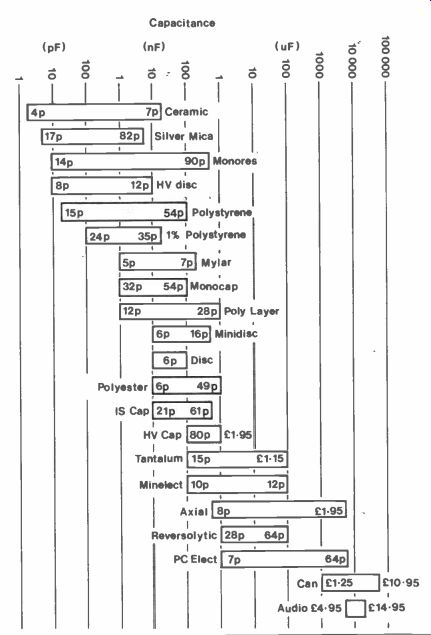
Figure 1. Capacitance range offered by different types.
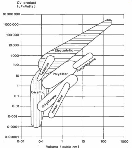
Figure 2. CV product and volume of capacitor range.
Temperature
Capacitance varies with tempera ture, although usually not very much. Its temperature dependence is known as its 'Tempco' (short for 'Temperature Coefficient,' though it sounds more like the name of a secretarial staff agency!). Tempco is measured in parts per million per degree C (ppm/°C) or as the percentage variation from its value at room temperature. Table 1 shows that plastic film capacitors are the most stable-their value changes by less than 1% between 0 and 50 degrees C. Over the same temperature range, electrolytics might vary by 5% or so, but ceramic-based capacitors could be as much as 25% less in value at 0° and at 500 than they are at room temperature! Imperfections The impedance of a perfect capacitor is always inversely proportional to frequency; its insulation resistance is infinitely large, and it never absorbs energy from the ripple current flowing through it. Unfortunately, perfect capacitors exist only in textbooks, and real capacitors suffer from all these defects to a greater or lesser extent. The capacitor's equivalent circuit, see Figure 3, shows how the imperfections can be modeled as series and shunt resistances, and series inductance.
Insulation Resistance
Some applications demand a capacitor having a very high effective parallel resistance -- timing circuits, or sample-and-hold circuits, for instance.
But as Table 1 illustrates, all except electrolytic types have an insulation resistance measured in thousands of Megohms.
Electrolytic and tantalum types have a small but continuous leakage current flowing through them. This current increases with temperature (reaching about twice its room temperature value at 50°C), and also with applied voltage.
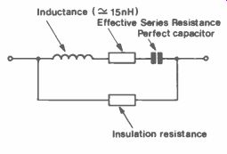
Figure 3. Capacitor equivalent circuit.
Self-Resonance
The inductance of a length of straight wire is about 15nH per cm.
Simple theory says that if each lead of a perfect 0.1uF capacitor is 5mm long, the resulting tuned circuit will resonate at a frequency of 4MHz. At frequencies below resonance, impedance falls as frequency rises and the combination behaves like a capacitor. But at frequencies above resonance the impedance rises with frequency: the capacitor behaves like an inductor! At the other end of the scale, if the component in question is a real 100,uF capacitor instead, then self -resonance occurs at just a few tens of kHz.
The moral is to use the smallest component with the lowest practical value, and to keep the leads (not forgetting the wiring and/or the PCB track) as short as possible if the self-resonant frequency must be high.
Power factor and tan d
Manufacturers don't usually quote the size of the Effective Series Resistance (ESR) for their capacitors directly.
Instead, they define the component's power factor, where:
Power factor = Effective Series Resistance Total impedance
Or more commonly, its dissipation factor:
Dissipation factor = tan d tan d = Effective Series Resistance Capacitive Reactance
The two terms are almost identical provided ESR is small. Both are obviously frequency-dependent; they are often specified at a frequency of 1kHz or 10kHz.
It is straightforward to extract a value for ESR from the power factor. The 0.1µF Poly Layer capacitor, for example, has a power factor quoted as 0.008 at 1kHz. At this frequency the capacitive reactance is 15901/, so:
ESR = 0.008 x 1590 = 13 ohms.
Any current flowing through the capacitor flows also, by definition, through the ESR. Suppose the capacitor is carrying a ripple current of 50mA at 1kHz. The power dissipated in the ESR -- and, hence, in the component -- is then:
P= 0.05 x 0.05 x 13 = 33mW
Electrolytic & Tantalum
Though they pack a lot of capacitance into a very small space, electrolytics are not precision components.
They are generally sold with a tolerance of ± 20%, or even + 50%/- 10%. They are polarised, and therefore are intended to work in situations where a constant DC bias appears across them (though some can withstand a small continuous reverse bias); the bias voltage causes a leakage current of typically 1µA or so to flow continuously through them. Electrolytics are made in values from 0.1µF upwards, although the high-frequency performance of the larger ones is often poor. A high frequency, for an electrolytic, can be as low as only a few kHz.
Ceramic
The properties of a ceramic capacitor depend very much on the type of dielectric that it employs. So-called "low - K" types are available at 5% tolerance from a few pF to a few nF. They have excellent temperature stability and a low dissipation factor.
"High -K" types by contrast may show a startling decrease in capacitance from the value quoted at room temperature. They are available in values from a few nF to and are used mainly in decoupling applications where their loose tolerance (10% or 20%) and poor dissipation factor are less important than their compactness, low inductance and low cost.
Polyester and Polycarbonate
Metallized film and foil capacitors are manufactured in values from 100pF to a few k/F, usually at 10% tolerance. Their chief attraction is their low dissipation factor, particularly at low frequencies, but their performance may be good enough for some filter applications despite their relatively high Tempco (typically 300 ppm). They are often much cheaper than ceramic types, albeit physically larger.
Polystyrene
Their high stability and tight tolerance make polystyrene capacitors the obvious choice for precision work. They are available in 1% and 5% tolerances, from a few tens of pF up to 100nF. They have a moderate Tempco (typically -150ppm) and a low dissipation factor, even at high frequencies. At small values they can be much more expensive than equivalent ceramic types, but from about 1nF upwards they have no real competition.
Silver Mica
Silver mica capacitors also have good stability and tight tolerance but their high price makes them difficult to justify for most applications. Like low -K ceramic types, they are available in values from a few pF to a few nF. The two types are physically much of a size, especially at low values, but silver mica capacitors can cost more than twice as much.
Summary
Each of the capacitor types described in this article is ideal for some particular task - and woefully inadequate for others. Picking the most suitable type involves deciding which properties matter most for the application you have in mind. Must the component fit into a very small space? Must its value be stable over a wide range of temperatures? Must it have very low loss? Armed with the answers to these questions, you can use the catalogue to identify just the component you need. Of course, it may not yet exist.