by Graham Dixey C.Eng., M.I.E.R.E.
More Jumps
The true jumps are JR and JP, discussed last time, but a number of related operations are included for convenience in the same table.
There is the CALL instruction, which is used when you want to access a sub routine. In assembly language, the operand for CALL is the label or symbolic address by which the sub routine is known. For example, a sub routine that develops a fixed time delay might be known simply by the label DELAY, and be located at an address &5CCO. In assembly language we get:
CALL DELAY which, in machine code, is CD CO 5C.
However, CALL is much more useful than just that. The CALL to the sub routine can be made unconditionally (as in the above example) or subject to one of a number of conditions (carry, non-carry, zero, non -zero, etc.) just as for the jumps JP and some JRs. This raises an obvious question. If there is so much similarity between CALL and JP, what's the real difference? It's an important question and the answer is as follows.
When a jump, whether JP or JR, is made, the contents of the program counter PC are simply replaced by the address of the destination for the jump. The old PC contents are lost and thus there is no provision for returning from whence you came. Usually this doesn't matter otherwise jumps would be of little use. The CALL instruction, on the other hand, recognizes the fact that the main program is only being left temporarily (to execute the sub-routine) and a return is intended. Thus, CALL does two things. It changes the PC contents to access the area of memory where the sub -routine resides and saves the old PC by 'pushing' it onto the 'stack'. This provides an opportunity to introduce another instruction from the set, RET (obviously short for RETURN), which must be included at the end of the sub -routine for, when it is executed, it 'pops' the old PC off the stack and the program continues from right after where it left originally when told to by the CALL instruction.
Incidentally, the RET instruction is unconditional or subject to exactly the same choice of conditions as the CALL instruction. Figure 1 shows the use of CALL and RET.
There is a particularly useful instruction in this group, which has the mnemonic DJNZ (Decrement and Jump if Non -Zero). Decrement what? The answer is the B register. This register can be set up as a counter, loaded with any value from &00 to &FF that determines how many times the loop is to be executed.
DJNZ is included within the loop and acts as a relative jump back to the beginning of the loop as long as B is not zero. Since, every time that DJNZ is encountered, B is automatically decremented, the program will eventually exit the loop when B becomes zero. Here's an example.
LD B,&OA LD C,8,0C LD A400 LOOP: ADD A,C DJNZ LOOP LD DUMP, A Load B with ten (80A) Load C with twelve (80C) Set A register to zero Add C to A Decrement, jump if B not zero Send result out
This simple program causes A to increase in value by a fixed amount (twelve) each time it goes round the loop.
Thus, by going round the loop a given number of times (in this case ten), the product of these two numbers is obtained. Obviously the application is limited but it does illustrate the way in which the DJNZ instruction works.
There are just two instructions left in this set, RETI and RETN, which are both return instructions similar to RET discussed previously. However, they relate to 'return from interrupt' rather than from a sub-routine.
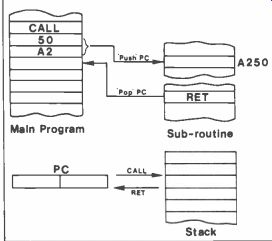
Figure 1. Use of the CALL and RET instructions.
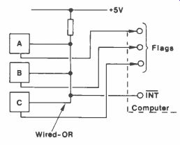
Figure 2. Three peripherals A, B and C connected to a common interrupted
line.
So just what is an interrupt? In brief, it's a way of getting the computer to run a particular program and yet be able to handle peripherals, apparently at the same time. Suppose there are three peripherals, known as A, B and C, as in Figure 2. Each of these is connected via a wired -OR configuration to an 'interrupt pin' on the CPU. Each of these peripherals has a flag which is connected to an input port line on the computer.
Suppose the latter is happily working away on some task and peripheral A has some data that it wants to send to the computer for processing. How can it let the computer know this? By interrupting!
*5V Wired -OR
0 Flags INT ComEuter
Figure 2. Three peripherals A, B and C connected to a common interrupted
line. It takes the interrupt line low and this initiates a sequence of
events that includes pushing the PC (and usually other registers as well)
onto the stack and going to an Interrupt Service Routine.
But the computer has to decide which of the peripherals actually interrupted, which it does by testing the flags, since the peripheral that interrupted will have its flag 'high'. Then having identified the interrupting peripheral, it will go to a service routine for that peripheral. The sequence is very much like that when a sub -routine is called. But there are important differences. The manner in which it is initiated is quite different. Also the peripherals can be assigned different priorities, thus ensuring that if two or more interrupts occur at once, the most important will be serviced first. Once the service routine is complete a return must be made to the original program. This is accomplished by using the RETI instruction, which 'pops' the PC and other registers off the stack.
However, this hasn't explained what the RETN instruction does. Well, it does the same thing as RETI but for what are called 'non-maskable interrupts'. The term 'mask' is used here in the sense of inhibiting an action, i.e. preventing an interrupt from having any effect on the CPU. Does this seem a strange thing to want to do? Not at all. If there are several peripherals, one of which has interrupted and is being serviced and another, less important one, decides to interrupt also, it shouldn't be allowed to until the previous peripheral has finished. Thus a mask bit is set to prevent this. However, if there is an emergency situation, this must be given top priority, which is done by assigning it to a non-maskable interrupt.
The Z80 has two separate interrupt pins.
Pin 16, INT, is where the regular interrupt line is connected. Pin 17, NMI, is used for the high priority non-maskable interrupts. The rule is, use RETI for INT interrupts, and RETN for NMI interrupts.
Skew Operations
This group of operations includes the 'shift' and 'rotate' instructions. The first four rotations are RLC, RRC, RL and RR. Rotations may be made to the left or to the right, and may be 'through the carry' or 'with the branch carry'. Figure 3 shows how the operations are carried out. There is a general pattern about them so, once one is understood, the rest follow easily enough.
Taking the rotations first, RLC is a 'circular left rotation', in which all bits shift left and bit 7 goes into the carry flag CY as well as 'round the loop' into bit 0.
RRC is simply a rotation in the opposite direction with bit 0 ending up in the carry flag. These rotations may be compared with the next two, RL and RR, in which the carry flag is 'in series' with the rotation. In RL, whatever is in the carry flag goes into bit 0 and bit 7 goes into the carry flag; in RR the exact reverse happens. There are four instructions RLCA, RRCA, RLA and RRA that duplicate the four just described but act on the A register only. They are a hangover from the 8080 from which the Z80 was _ developed. The Z80 instructions allow all of the registers to be operated upon as well as memory locations addressed by HL, IX or IY.
Now for the shifts. These may be to the left or the right and also involve the carry flag. However, there is no closed loop, just a series chain. For example, SLA is the Arithmetic Shift Left; all bits shift left one position, the carry flag and a zero enters bit 0.
The carry flag CY is often called a 'carry link' because it allows one register to be linked to another and data passed serially between them. For example:
LD A,&00 LD C,&OFF LD B,&08 LOOP: SLA C RL A DJNZ LOOP
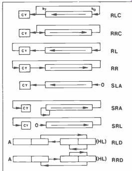
Figure 3. Effects of the 'skew' operations.
This program will serially shift the contents of register C into register A with eight consecutive left shifts determined by the DJNZ instruction. However, serial shifting between registers (which includes memory locations) is not all that can be done. Every left shift multiplies a number by two, as the following sequence shows.
Original byte -
00001011 = 11 (denary) 1st shift left
00010110 = 22 2nd shift left
00101100 = 44 3rd shift left
01011000 = 88 4th shift left
10110000 = 176
At which point the carry flag must be used to link this byte to another register to avoid the m.s.b. falling off the end! SRA is the Shift Right Arithmetic instruction, which is not a simple reversal of SLA. The difference lies in that, instead of a zero entering bit 7, the current value of this bit remains unchanged, thus preserving the 'sign' of the number. The remaining seven bits can be transported across to another memory location, via the carry link, but using the RR instruction on the other location. Each successive shift right divides the number by two, for positive numbers only and only if no ones fall off the rightmost bit position--a simple but limited means of performing binary division.
The difference between SRA and SRL is that the latter is a Logical Shift Right, and a zero enters bit 7 when shifting.
The two instructions RLD and RRD stand for Rotate Digit Left and Right respectively. They are used in Binary Coded Decimal (BCD) arithmetic, in which the digits 0-9 are encoded as four-bit binary groups (0000-1001) or 'nibbles'.
They act on data in the A register and a memory location pointed to by HL.
Figure 3 clearly shows the re-arrangement of nibbles that occurs for each RLD or RRD instruction, all data moving simultaneously.
Bit Manipulation Group The instructions in this group allow bits in various registers or indirectly addressed memory locations to be tested for their value (BIT), set to logic 1 (SET) or reset to logic 0 (RES). This is done by specifying the bit number (0-7) and the register. For example:
SET 2,C Will set bit 2 of register C to logic 1.
RES 5,A Will reset bit 5 of the A register (to logic 0), while: LD HL,&A200 BIT 3,(HL)
Will test bit 3 of memory location &.A200 and will set the zero flag in the flags register F if the bit is found to be zero.
The ability to manipulate or test bits in registers or memory locations on an individual basis is a very useful one.
General Purpose AF Group
There are just five instructions in this group, which are concerned solely with the A register or the flags (F) register.
The first of these, Decimal Adjust A register (DAA) is used when arithmetic is to be done in BCD. The problem arises because the CPU can only work in binary and special provision must be made to compensate for errors that may arise when working in another system. As we know, BCD uses four bits to encode the denary digits 0-9, i.e. uses the groups 0000 to 1001. But what about the remaining possible groups, 1010 - 1111? These can obviously occur in binary addition and subtraction yet have no meaning in BCD - they are 'illegal' codes.
It is possible to skip over these six illegal codes by adding six to the result whenever such a code occurs. Consider the following BCD addition of 35 and 22.
0011 0101 (35) + 0010 0010 (22)
0101 0111 (57)
The answer 57 is obviously correct.
Now see what happens with the sum of 35 and 25.
0011 0101 (35) + 0010 0101 (25)
0101 1010 (5?)
The second nibble of the result is one of the illegal codes.
Now add 6 to the result and see what happens.
0101 1010
0110
0110 0000 (60)
The corrected result is now right.
Fortunately we don't have to worry about when to add six or whether it should be added to the low nibble or the high one, or even both. On receipt of DAA, the CPU tests the flags and decides for itself what to do.
The DAA instruction should follow when operating in BCD with any of the following instructions, ADD, ADC, INC, SUB, SBC, DEC, NEG.
CPL is a useful single -byte instruction which complements the contents of the A register, that is swaps is for Os and vice-versa.
LD A,&2C CPL
The above example means that the A register is loaded with 00101100 (2C) which, after the CPL instruction, becomes 11010011 (D3).
NEG means 'negate the A register', e.g. if the number held is a positive one, then form the two's complement of it.
&OF (+15) becomes &F1 (-15)
&E2 (-30) becomes &1E (+30)
The final instructions in this group are CCF (Complement Carry Flag) and SCF (Set Carry Flag). CCF inverts the value of the carry flag, while SCF forces it to logic 1.
Restarts This group of eight instructions is a special set of sub-routine calls, whose origin addresses are &00, &08, &10, &18, &20, &28, &30 and &38. Commonly used sub-routines can be called from these addresses and require only a single-byte instruction.
For example, RST 20 calls the sub routine whose origin is at the address &0020. Somewhat confusingly these restarts are sometimes referred to by their denary values, i.e. RST 32 may be used instead of RST 20.
Control Instructions
The first instruction in this group is NOP, which stands for No OPeration, meaning that the CPU does precisely nothing during the time of this instruction.
It can be useful, however, to insert a few NOPs into programs sometimes, so that program changes can be accommodated more easily by changing them to active instructions. They can also be put into a loop to act either as a short time wasting program, or where an interrupt is anticipated and the machine must be idle, such as in keyboard input routines, thus:
WAIT: NOP JR WAIT
The CPU obediently cycles back and forth between the two lines until the interrupt breaks into the loop. HALT could be used instead, since this will stop the operation of the CPU until either an interrupt is received or the reset pin (pin 26) is taken low. The remaining five instructions are all concerned with interrupts and work as follows:
D1 and E1 stand for 'Disable Interrupts' and 'Enable Interrupts' respectively.
Earlier it was said that various interrupts can have different priorities. Thus, if a high priority interrupt wishes to ensure that it cannot be over-ridden by one of lower priority, the first thing it does when it goes into its Interrupt Service Routine is to disable further interrupts with the DI instruction. Then, when it has completed its routine it will issue the E1 instruction to allow further interrupts to be acknowledged by the CPU. The last three instructions are concerned with the interrupt modes of the Z80 and require more detailed discussion.
IMO sets mode 0. This can be referred to as the 8080 mode, since it is compatible with the older 8080 CPU. In this mode, when an interrupt is received, the PC is pushed onto the stack and the Z80 passes control of the data bus to the interrupting peripheral. The latter responds by placing an instruct ion on the data bus, which is usually a sub -routine call to execute the service routine for that particular peripheral.
One of the restart instructions may be used for this.
EMI sets mode 1, which is the 'polled response mode'. When an interrupt is received the CPU calls a sub -routine located at the restart address &0038.
This will then poll the various peripherals to ascertain which one interrupted and then will service that peripheral.
1M2 is the most powerful of the Z80 interrupt modes. It uses a register, the I or Interrupt Vector register, which has to be loaded with the high byte of the interrupt vector. The low byte is supplied by the interrupting device itself. This complete vector then points to two consecutive locations
that give the start address for the service routine. This is not as complex as it may sound and is illustrated in Figure 4.
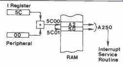
Figure 4. The Z80 Mode 2 interrupts.
The Input-Output Group
And so to the final set of instructions for the Z80, those that deal with the transfer of data between the CPU and the outside world through interface chips such as the Z80 P10.
Unlike the 6502, the input/output ports on a Z80 system are not memory-mapped, i.e. they do not have memory addresses on the main memory map of the computer. Instead they are identified by 'port addresses', which are usually in the range &00 - &FF (which allows for 256 separate ports). In theory it is possible to have 65536 individual ports - the mind boggles! This number held in the A register (the high byte) with the operand of the instruction (the low byte) to give an address range for the ports from &0000 - &FFFF.
To fetch data from a port, the IN instruction is used together with the destination register and the port address, thus:
IN A, &02
Will fetch the data at port &02 and place it in the A register.
Data is sent to the port by using the OUT instruction, the port address and the destination register, so that:
OUT &02, A
Will send the contents of the A register to port &02. The other general purpose registers can also be the subject of IN and OUT instructions, but by means of register indirect addressing, using the C register. Thus, to send data from the D register to port &02 and then input data from port &03 into the E register, the following program could be used.
LD C, &02 OUT (C), D INC C IN E, (C)
There is also a range of block transfers for IN and OUT, that work in essentially the same way as the block transfers described in Part Three. IM is used to fetch data from a port and load it into a block of sequential memory locations and vice-versa for OUTI. In both cases the I stands for Increment. If, instead, the instruction INIR or OUTIR is issued the process of transferring data and incrementing to the next address is done automatically until the whole block has been transferred. In this type of transfer HL is first loaded with the start address of the block, B with the number of bytes to be transferred and C with the port address. Consider the following program:
LD HL, &A200 LD B, &32 LD C, &02 INIR
This will load the block of memory &A200 - &A231 with the fifty bytes of data, specified by the B register, from port &02.
If INI is used instead of INIR only one byte is transferred, but HL is incremented and B decremented ready for the next INI.
In both cases the transfer is complete when B = 0 though, in the case of INI, this must be ascertained by testing the Z flag after each transfer to see if it now equals 1.
Analogous to INI, INIR, OUTI and OTIR are IND, INDR, OUTD and OTDR.
The D, of course, stands for Decrement and refers to the fact that at each transfer HL is 'decremented' instead of being incremented. As a result, HL initially holds the 'top' address of the memory block, which is then loaded 'downwards'.
Some of the descriptions may have been fairly brief, but all of the Z80 instructions have now been discussed.
This means that future articles can deal entirely with the writing of a variety of programs in Z80 code, on the assumption that all mnemonics may now have some meaning, even if it does sometimes mean a quick look back to earlier issues.