AMAZON multi-meters discounts AMAZON oscilloscope discounts
Overview
The design of control centers must meet the codes and regulations in effect at the site as well as the requirements for the plant's operation. Control centers, also commonly referred to as "control rooms," form the nerve center of a plant. They are generally air-conditioned, sometimes pressurized with clean air, and their temperature and humidity are controlled to preset conditions. Additional information is available from ISA-71.01-1985, Environmental Conditions for Process Measurement and Control Systems: Temperature and Humidity.
AMAZON multi-meters discounts AMAZON oscilloscope discounts
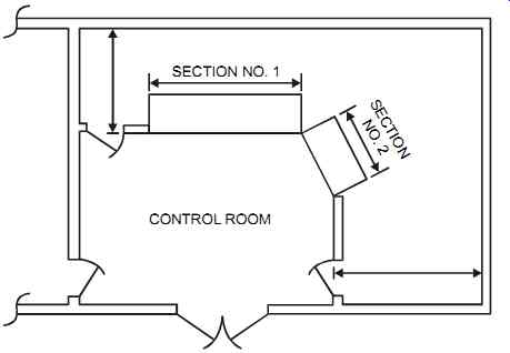
When designing a control center, the designer must develop a layout (see FIG. 1) and ensure that the center's design and use conforms to good engineering practice and standards. A good source of information on these is ISA's RP60 series of recommended practices for control centers. Some of the items that should be addressed when designing control centers are design, physical aspects, security, fire protection, air conditioning, electrical/electronic, and communication. These are discussed in this Section.

FIG. 1 Example of a control center layout.
Design
Many points should be considered when designing control centers. For example, the control room should be located, whenever possible, away from sources of vibration and completely protected from heavy rain, external fire-fighting water, and the like. In some cases, the control room must be earthquake-proof. For safety purposes, no process lines should enter the control room except for instrument air. The electrical area classification should be taken into account when locating and designing the control room.
Where required (and where economically justifiable), the control room may need a false floor for the passage of cables and/or tubing. In this case, smoke detectors should be installed underneath the false floor, and the floor should be made of a flame-resistant and anti-static material.
Where equipment has to be accessed, space should be allowed between that access area and the nearest obstruction (such as a wall), with a minimum of 3 ft (1 m) clearance. In most cases, control room doors should be of the self-closing type.
To avoid electrical noise, high-voltage cabling should be routed at a 3 ft (1 m) distance from low-voltage cabling. Also, to avoid unnecessary noise, air conditioning units are typically kept outside the room. There should be a minimum of two sockets in the control room for portable power tools and other uses.
Easy and safe access must be available so the control room equipment can be brought into the room. As obvious as this may sound, many control rooms were completed before it was realized that the purchased equipment would not fit through the doors. Construction and ware housing personnel should coordinate to ensure that openings are left in walls so large equipment panels can be installed.
Physical Aspects
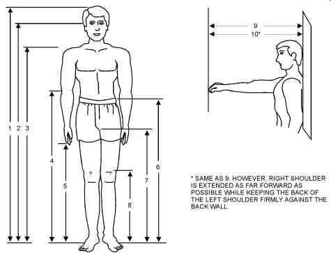
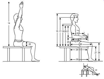
When designing control centers, the physical characteristics of the operators should be considered. For example, the distance the operator must move should be considered and reflected in the design. Locating controls in hard-to-reach areas that require extreme physical movement will produce fatigue and should be avoided. The dimensions shown in FIG. 2 and 3 as well as in tables 1 and 2, reflect the static anthropometric data. It may be refined to reflect the physical characteristics of a given plant's actual operators.
Control room design should have a good ergonomic layout. Details such as the type of chairs used, their ability to adjust height and tilt, and the type of armrests selected are all important factors. Operator comfort is directly related to operator performance and efficient plant operation.

FIG. 2 Standing body dimensions.

FIG. 3 Seated body dimensions.
TABLE 1 Standing body dimensions. (coming soon)
TABLE 2 Seated body(coming soon) dimensions. (coming soon)
Security
If the control center is considered a high-security area, the entrance will have to be restricted and a means for maintaining this restrictiveness incorporated. This is generally accomplished by requiring the use of badges or magnetic cards and permitting only approved personnel into the control room.
Another aspect of security is access to software and software management. It is good practice to have duplicate copies of software stored in separate locations and to maintain control over who has access to these storage areas.
Fire Protection
The fire protection system in the control center must conform to the requirements of the local codes and regulations as well as the requirements of the insurance companies. The fire protection system must be designed by qualified fire protection specialists.
When plant designers assess the fire hazards, they must make a determined effort to reduce fire hazards by constructing the control room (including the floor) of noncombustible material and reducing stacks of paper. It is good practice to have a separate area for high-risk devices (such as printers) unless they must be in the control room. If they are, then the storage of paper in the room should be kept to a minimum. The designers should assess whether records (or tapes) should be stored in fire-proof safes, in the control room, or in a remote area.
The use of a safe fire-protection fluid will ensure that the fire protection system poses no harm to the control room operator. In addition, hand-operated fire extinguishers of dry CO2 are usually stored near the exits of most control rooms. The room is usually designed with emergency lighting since non-essential power services will shut off during a fire, and means should be provided to ensure that power supplies can be manually or automatically isolated.
Placing basements below control rooms is not recommended because they may collect water from fire-fighting or even from rain. Also, in control rooms with false floors, water may accumulate under the floor. A water detector may therefore be required.
Air Conditioning
Air conditioning maintains a comfortable working environment for the operators while dissipating the heat that is released by all the equipment in a typical control center. The air-conditioning unit must be sized to maintain temperature and humidity within the requirements of the control systems, for example, around 75°F (24°C) and 50% RH. The air conditioning air intake must be located where it will supply clean air to the control center even during an abnormal situation such as the discharge of a nearby relief valve. Under nor mal operating conditions, air conditioning maintains a comfortable working environment, but during a power failure the air-conditioning unit will stop. Heat will begin to build up because in most plants the control system will remain operational since it may be on stand-by power.
Control room design for critically hot environments should consider installing more than one air-conditioning unit in case one unit fails. Additional information on control room tempera ture and humidity conditions is available from ISA-71.01-1985.
Pressurized rooms located in hazardous locations must conform to the code and statutory requirements in effect at the site (such as NFPA 496). They should be clearly marked with the following:
• a notice stating "WARNING - PRESSURIZED ROOM";
• a warning located at both the control switch for the source of pressurization and at the relevant points of electrical isolation that indicates the time in minutes for which purging is to operate before the electrical supply can be switched on or restored; and
• a warning at all entrances to the pressurized room against introducing any flammable materials.
Electrical/Electronic Considerations
The design of a control center must ensure that all electrical peripheral functions such as grounding, lighting, and electronic interference suppression are correctly implemented. All power and chassis grounds and cable shields should be connected to the grounding electrode in conformance with the recommendations of the system vendor. Cabling in and out of the control room must go through wall penetrations and must be adequately sealed to prevent the entry of water.
In situations where both electrical power services and control signal cabling are distributed using subfloor cable trays, the design should ensure that the trays for electrical power distribution and for control and communication signals are kept a minimum of 3 ft (1 m) apart and cross at right angles only. This will minimize the potential of generating electrical noise. To prevent electronic interference, susceptible equipment (such as microcomputers and networks) should be kept far from high-power electrical equipment.
Lighting requirements should be evaluated. For instance, the lighting needed to monitor display areas is typically less than that required for printers and disk drives. However, for maintenance purposes, strong lighting is needed throughout the control center. Control center lighting may be provided by fluorescent fixtures mounted above parabolic egg-crate-type ceiling panels (to diffuse light and minimize glare on displays). Dimmers should be used to control different sections of the control center. There should be at least two independently controlled circuits: one for general room lighting and the second for monitor display lighting. And, if lighting is not supplied from the UPS, there should be a separate emergency light in the control center.
Communication
In many modern control centers walkie-talkies are not allowed. A sign to that effect may be installed on the control center door. This is done to avoid the effect of electrical noise that walkie-talkies generate. In such cases, an FM transceiver with a roof-top mounted antenna is supplied to make possible communication with field operators who are using walkie-talkies.
Inside the control center, movable microphones (or telephone handsets with long cords) should be provided on each console. Walkie-talkies should operate on a unique assigned frequency to avoid interference from other nearby units and operations.