By WARREN BAKER
Budget dual-regulated power supply with common ground adds test-bench punch for project builders.
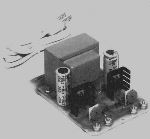
A VARIABLE-VOLTAGE POWER SUPPLY FOR THE ELECTRONICS test or project bench can become a very worthwhile project for the electronics experimenter, ham radio operator, amateur or pro repairman, or hobbyist. The project presented here not only offers simplicity and low cost to assemble, but also contains two identical adjustable power supplies on the same small circuit board with each supply regulated independently, but sharing a common ground.
A quick glance at the schematic diagram of the Dual Variable Power Supply (Fig. 1) will reveal the above-mentioned simplicity and at the same time point out that the dual heart of the power supply is really two regulator integrated circuits, IC1 and IC2. The diagram also makes it apparent that the two supplies differ only in their polarities with the upper one in the schematic diagram providing a positive output while the lower one is negative in respect to the common ground connection shown. Each supply can be operated independently of the other for general use where no common connections exist between the units under test.
However, one important use for the power supply will be during experimenting with operational amplifiers (op-amps), which oftentimes require a so-called "split" power source with the positive and negative terminals both being isolated from the common ground of the op-amp. In this case, the Dual Variable Power Supply is a natural.
Although no enclosure or case is shown, the Dual Variable Power Supply may be mounted in any convenient cabinet that the builder may have available. Or, if desired, it can even be installed into the bench where most of the uses will be found. The power supply's small size, 3 1/2-in. wide by 5 1/16-in. deep by 2-in. high makes it easy to add the unit into existing test equipment if desired. Otherwise, the power supply may be operated without a case without too much danger involved provided its base is insulated in the event it is placed on metal objects.
The two independently-adjustable regulated power supplies may be set to any voltage within the range of approximately 1.25 VDC and 15 VDC with each supply capable of delivering up to 750 mA of current to the load. The exact limit will depend upon the individual voltage settings at the time. Further, each supply is protected against thermal overloads by circuitry built into the IC regulators. All parts are common items and should be easily obtained from good electronics parts houses. In addition, parts, including the PC board (see Fig. 2), are available at the location listed in the Parts List. There is also a complete kit of parts available for those who prefer to go that route.
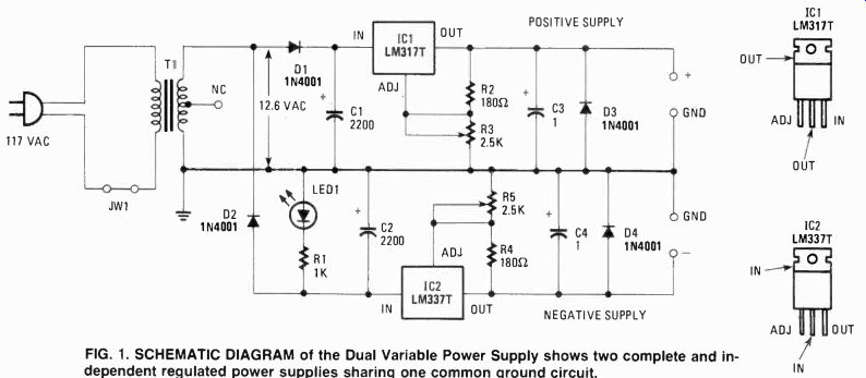
FIG. 1. SCHEMATIC DIAGRAM of the Dual Variable Power Supply shows two complete
and dependent regulated power supplies sharing one common ground circuit.
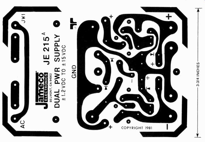
FIG. 2. FOIL SIDE PATTERN of the printed-circuit board the author used
to assemble this project.
The board serves as the chassis, mounting all parts including the power transformer.
--------------------
PARTS LIST
RESISTORS
R1-1000 ohms, 1/4-watt
R2, R5--180 ohms, 1/4-watt
R3, R5-2500 ohms, PC trimmer potentiometer
CAPA CITORS
C1, C2--2200 µF, electrolytic, 16 VDC
C3, C4--1 µF, tantalum, 50 VDC
SEMICONDUCTORS
D1-D4-1N4001
IC1--LM317T adjustable voltage regulator, positive
IC2--LM337T adjustable voltage regulator, negative
LED1--Jumbo red light emitting diode
T1-117 VAC primary winding, 12.6 VAC, 2A or better secondary winding, power transformer (Jameco F25X)
MISCELLANEOUS
Power cord with plug, rubber bumper feet, 6-32 and 4-40 hardware, two heatsinks (THM 6030 or equivalent), printed-circuit board or perfboard, wire, solder, etc.
The kit of parts and printed circuit board for the JE-215 Dual Voltage Power Supply is available from: Jameco Electronics, 1355 Shoreway Road, Belmont, CA 94002 (Tel: 415/592-8097) for $24.95 plus $2.00 for shipping and handling. California residents must add 6% state tax.
Jameco Electronics will shop C.O.D. but will not take charge cards. Orders may be placed by mail or phone-phone orders taken Monday thru Saturday 8 AM to 5 PM PDT.
---------------------
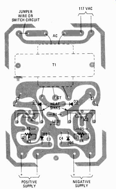
FIG. 3. PARTS LAYOUT AND IDENTIFICATION on the printed-circuit board. Foil
pattern is on the bottom surface and shown here in gray. Large foil solder
pads made job easier.
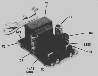
------ HERE IS WHAT YOUR DUAL VOLTAGE POWER SUPPLY will look like
when completed. Unit can be used "as is", or boxed in a cabinet,
or incorporated into a project.
Putting it together
Quite naturally, construction time will vary according to many factors including the individual's own abilities.
However, assuming that the builder has already rounded up all the required parts and has a pre-drilled and etched PC board on hand, there can be little reason to anticipate spending more than one evening building the Dual Variable Power Supply. Using point-to-point wiring may take slightly longer, since the parts must be attached to a chassis or perfboard.
If you are using the printed-circuit board approach, the recommended procedure for assembly will begin by installing four diodes, D1 through D4, in the positions shown on the parts layout in Fig. 3. Use caution to be certain that their polarities are as indicated by the color band on each unit. The diodes should be mounted about 1/8-inch above the board surface. Following the soldering and trimming of excess lead lengths of the diodes, proceed to the installation of resistors R1, R2, and R5 making sure that the color-coded values are installed in the proper locations as shown. Insert and solder the two tantalum tie capacitors shown as C3 and C4 making sure that the positive (+) lead of each capacitor is oriented correctly.
Next insert power transformer T1 leads into their proper locations on the printed-circuit board after cutting them and stripping the ends. Mount the transformer using 6-32 x 3/8-in. binding-head machine screws and nuts. The screws should be inserted through the board from the bottom (foil side) and a lock washer should be placed under the nuts to secure the transformer mounting tabs. If other than the specified transformer in the Parts List is used, the lead positions and the mounting holes, sizes and placement will vary.
The IC regulators, IC1 and IC2, may now be positioned onto the board; be care to install the proper IC at the correct location. See Fig. 3. Before soldering the IC's, push their leads about Vs-in. into the holes and proceed to install the heat sinks onto the board through the holes provided. Allow about '/s-in. of air space between the bottom of the heat sinks and the top of the board. Secure the IC's to the heat sink using 4-40 x 3/8-in. hardware, and solder their leads to the board.
Trim leads as required.
Electrolytic capacitors C1 and C2 may now be inserted onto the board making sure once again that their polarities are properly oriented. Note that the positive (+) leads are at the top and are folded down alongside of the capacitors' bodies in order to enter the proper holes. Leave about 1/8-in. under the board, bend 90-degrees, and solder to foil.
Light-emitting diode LED1 can be inserted through the holes in the board making sure to observe the proper polarity.
The leads should be pushed into the board to the point where there is approximately 3/4-in. of clearance between the bottom of LED 1 and the top of the board. Solder and trim excess leads. If that lamp fails to operate when the power supply is completed, check the connection and polarity.
Voltage-adjusting potentiometers R3 and R4 may now be inserted into the locations shown in Fig. 3. Some straightening and re-forming of the leads will most likely be required.
The bodies of those variable resistors should be mounted flush with the printed-circuit board in order to provide more mechanical strength to their mounting. At this point it is advisable to install the jumper wire designated as "PW-1" at the location shown on the pictorial layout chart. A piece of lead cut from one of the components installed earlier may be used for this purpose.
The power cord should now be connected to the board as shown in Fig. 3. The twisted ends of each lead should be inserted fully into the hole, bent back against the solder pads and soldered. Trim any excess wire ends. In keeping with safety guidelines, two pieces of 3/8-in. wide plastic electrical tape should be placed over the 120 VAC input traces (foil leads). In addition, to prevent any accidental breaking of the power cord connection, the lead should be folded back on the top side and secured by means of a cable clamp to one of the screw mounting securing power transformer T1.
Output connections for the power supply are fabricated by inserting four 6-32 x 3/8-in. machine screws through the holes at each output foil trace. Once again, as in mounting the transformer, the heads of these bolts are located on the bottom of the board. A 6-32 nut is threaded onto each bolt and tightened securely. A second 6-32 nut is now installed onto each bolt to act as a means of connecting wires to the power supply.
Final mechanical assembly will be obtained by cementing four small bumper feet to the underside of the printed-circuit board. The latter will serve to elevate the printed-circuit board away from any surface it may be operated on and also prevent the soldered joints on the underside from scratching that same surface.
Check it out
Before applying power to the newly-built Dual Variable Power Supply, recheck each component for proper location and polarity, using the layout chart as a guide. Pay particular attention to the proper installation of diodes D1 and D2 as well as IC1 and IC2. A mistake here could cause instant destruction of parts if incorrectly installed. If the power should fail to operate when plugged into the 120 VAC outlet, normal service checks should include being certain that the power cord is properly connected to the transformer's primary winding printed circuit tabs and that the secondary winding of T1 is connected to the circuit foils. A voltmeter will quickly confirm the presence of 12.6 VAC at the secondary terminals telling the builder that the problem is following the power transformer in the circuit. If LED1 glows properly, it also is a good indication that the transformer and D2 are operating correctly.
Once you have passed the "smoke test" area, but the supply still has no output voltage from one or both suppliers, your best action would be to recheck your wiring and soldering to be certain that the parts are installed in their proper locations and with the polarities indicated on the schematic diagram (Fig. 1) and component layout diagram (Fig. 3). Bear in mind that if you should find one of the diode rectifiers, or IC regulators, improperly installed, there is a fifty-fifty chance that it may be damaged.
Another possible trouble symptom could be the refusal of the output voltage to adjust in response to the voltage adjust control which will indicate a poorly soldered joins at one or more of the reference-voltage-resistance-divider chain. In practice, since the output voltage from the IC is applied across (for example) the series-connected R2 and R3 network (see Fig. 1), it will follow any up and down excursions which the load may tend to cause at the output. A portion of this, voltage change is tapped off by the variable resistor (R3) and returned as a reference voltage to be used by the IC which in turn either lowers or raises the output voltage. The net effect is to maintain a very stable output voltage. Therefore, as can be anticipated, a loose connection, short, or other defect in this reference circuit will cause a problem with the adjustment of the voltage as well. Defective or incorrectly installed electrolytic capacitors C3 and C4 will make the supply difficult to adjust and if the output voltage varies or drops under load, improper values of C1 and C2 may be suspected.
It is important to understand that the positive and negative supplies share a common ground connection. If the supply is used for two projects at one time, each supply may be called upon to provide the single polarity needed. For instance, two isolated units may be operated using 5 volts to each. One unit may be used in the normal manner across the positive supply while the second unit under test can be operated by the negative supply by merely reversing the leads at the supply
...positive lead to the ground terminal of the power supply and the negative (common ground) to the negative terminal of the power supply. It will not require much thought to realize that there can be no common ground connection between these two units under test since it would amount to a short across the output terminals of the power supply.
If the power supply is to be housed in a case or other enclosed area, be sure to consider the temperature rise that could occur unless proper ventilation is supplied. No fuse or on/off switch is provided on the power supply board. Such items may be inserted into the circuit by removal of jumper (JW1) and soldering their leads to these board terminals.
The low cost of construction of the Dual Variable Power Supply will provide a very valuable investment for your electronics experimenting and building projects by the convenience offered through the usefulness of having on hand a dual polarity, adjustable, and regulated power supply.