By DAVID LEITHHAUSER
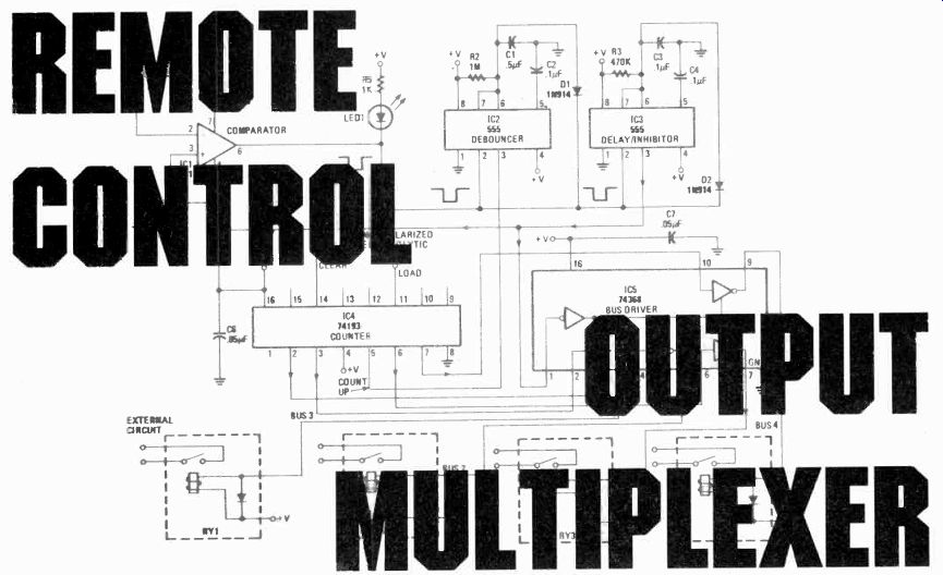
Turn on or off any combination of four electrical appliances by electrical impulses, sound, or light signals! THERE ARE A NUMBER OF PLANS AND COMPONENT KITS available that enable you to build sound- or light-activated switches and similar remote-control devices.
Now it is fairly simple to build a device that allows you to control up to four appliances with a single remote-control receiver, whether it is a sound-activated switch, a photocell, or a radio receiver. The remote-control receiver's output can be any voltage that can be caused to have positive (or negative) pulses. That is possible because the remote-control output multiplexer counts the number of pulses it receives to determine which appliances (relay) to turn on.
About the circuit
The output of the remote-control receiver is fed into the inverting input of comparator chip IC1 (Fig. 1) of the remote-control output multiplexer. That voltage is compared to a reference voltage applied at the non-inverting input of the comparator. When the output voltage of the remote-control receiver has a positive pulse that goes higher than the reference voltage, the output of the comparator (which is normally positive) has a negative pulse. If the remote-control receiver can only produce negative pulses, reverse the inverting and non-inverting comparator leads. That will cause a negative pulse from the remote-control receiver to produce a negative pulse from comparator IC1. When that happens, LED1 comes on.
Potentiometer R1 should be adjusted so that the LED is normally unlit, but lights up when a pulse is applied to the comparator. That will indicate that the reference voltage at the non-inverting of the comparator, IC1, is properly adjusted.
The negative pulse from comparator IC1 triggers two monostable multivibrators, IC2 and IC3 (made up of 555 chips). Note that each of these monostable multivibrators has a diode from pin 6 and pin 2. Those diodes keep capacitors C1 and C2 discharged when the comparator output is negative, so that the "on time" of the monostable multivibrators continues for a preset period after the end of a negative pulse from comparator IC1. That effectively stretches the pulse.
The first multivibrator, IC2, is really just a de-bouncer, to condition properly the pulses fed to IC3 (74193). Its time constant is very short. The second multivibrator, IC3, has a much longer time constant (about 3 seconds) and serves two purposes. First, on the first pulse it clears IC4 to zero so that it can begin counting. Second, it inhibits the relays through the IC5 (74368) tri-state control so that the relays do not start turning appliances on until all the pulses have been counted. It does not allow the relays to be energized until there have been no pulses for 3 seconds.
Chip IC4 produces a binary output that represents the number of pulses it has received, minus the first pulse because IC3 was resetting IC4 to zero at the same time the first pulse came in. That binary output is used to control the relays, after being inverted by the bus driver inverters in IC5.
Table I gives the condition of the relays after the train of pulses. In order to change any of the relays, it is necessary to begin a new train of pulses and create the new combination from scratch.
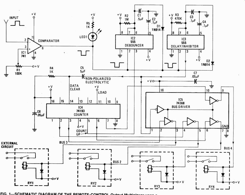
FIG. 1--SCHEMATIC DIAGRAM OF THE REMOTE –CONTROL
Output Multiplexer uses a pair of 555 chips, IC2 and IC3, as the system's timer. IC2 functions as a debouncer by shaping up the input pulse to a neat, clean square pulse. IC3 clears IC4 to zero at the beginning of a count, and prevents the relays from changing state until all the pulses have been counted.
-----------
Table 1
RELAY MULTIPLEX TABLE
Number of Pulses Relays Activated 1 None, all relays turned off 2 #1 3 #2 4 #1 and #2 5 #3 6 #3 and #1 7 #3 and #2 8 #3, #2, and #1 9 #4 10 #4 and #1 11 #4 and #2 12 #4,#1 and #1 13 #4 and #3 14 #4, #3 and #1 15 #4, #3 and #2 16 #4, #3, #2 and #1
-------------
PARTS LIST
RESISTORS
All resistors are 1/4 watt, 5% or 10%
R1-100,000 ohms potentiometer
R2-1 megohm
R3-470,000 ohms
R4, R5, R9, R10-1000 ohms
R6, R7-33,000 ohms
R8-Light dependent resistor
CAPACITORS
C1-.5 uF C2, C3, C8, C9-.1 uF
C3-05-5 uF non-polarized electrolytic
C6, C7--0.05 uF
SEMICONDUCTORS
D1, D2-1N914 or equivalent
IC1, IC6-741 Op-amp or type 308
IC2, IC3-555 timer
IC4-74193 counter or 74LS193
IC5-74368 hex bus driver or 74LS368
OC1--Opto-coupler to suit input circuit-see text
MISCELLANEOUS
RY1-Solid-state TTL compatible 5-volt relay with internal diode protection, Radio Shack 275-236 or equal 5-volt DC power supply, cabinet, AC sockets, etc.
--------------
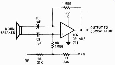
FIG. 2--YOU CAN ADD A VOICE ACTUATOR to the multiplexer as shown. The loudspeaker
functions as a dynamic microphone to detect handclaps and other "sharp" noises.
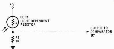
FIG. 3--INPUT TO THE COMPARATOR CIRCUIT can be controlled by a light-dependant
resistor. Almost any similar device can be adapted to function in this circuit.
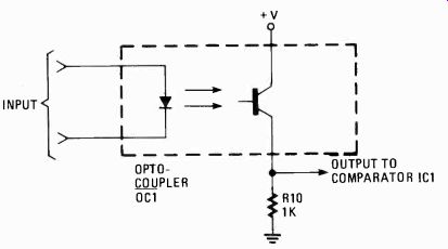
FIG. 4-OPTO-COUPLERS ARE AN OBVIOUS SELECTION for input signals to the
multiplexer. The type of light source used in the opto-coupler depends on
the external circuitry.
Examples of operation
Let's use the remote-control output multiplexer as a sound-controlled device. Op-amp IC6 in Fig. 2 makes a good input device. The output of the op-amp IC6 goes to the inverting input of the comparator the remote-control output multiplexer. When sound strikes the mike (the 8-ohm speaker), voltage oscillations are produced at the output of the op-amp, IC6. Potentiometer R1 should be adjusted so that the reference voltage at the non-inverting input of comparator IC1 (see Fig. 1) is a little higher than the voltage at the amplifier output when there is no sound present. That way the output of the comparator will normally be positive.
However, when sound strikes the mike, the voltage oscillations produced by IC6 cause the voltage at inverting input of the comparator, IC1, to go higher than the reference voltage. That will cause a negative pulse at the output of the comparator. Actually, it will produce a burst of pulses, but the debouncer action of IC2 will condition those spasmatic pulses into one pulse, provided there is no pause in the sound. That is, each clap, word or sylabant counts as one pulse. Any pause between claps or words (if you speak each word distinctly) allows IC2 to reset and wait for a new pulse.
The reference-voltage control R1 (see Fig. 1) will act as a sensitivity control, since setting it at a high voltage means that a loud sound is required to produce voltage oscillations large enough to pass that voltage level. The sensitivity control must not be set too high, or glitches will register as pulses. If that happens, the glitch caused by the activation of the relays will be read as a single pulse, turning off all relays the instant they are turned on.
Another useful control device is the photocell voltage divider shown in Fig. 3. Light striking the photocell drives the output high enough to pass above the reference voltage. Using an ordinary flashlight to send flashes of light to the photocell, a person can operate four appliances by remote control.
If you wish to use the remote-control output multiplexer with a remote-control device that cannot be run on 5-volts, the circuit in Fig. 4 will couple virtually any remote-control receiver to that device. All that has to be done is to select the opto-coupler to have a light source such as a LED, neon lamp or filament device, and match it to the pulse input circuit.
Construction
The remote-control output multiplexer can be mounted using printed circuit, wire wrapping, or point-to-point techniques. Wires should be kept as short as possible due to the TTL counter, IC4. The relays will not require heat sinks unless the appliance draws a considerable amount of current. Be sure to include the 0.05 µF anti-glitching capacitors (C3 and C4) on the 74193 and 74368, IC4 and IC5, respectively.
What is interesting about this project is that selected portions of the Remote Control Output Multiplexer may be used in other projects of your own design. The debouncer and delay/inhibitor circuits, IC2 and IC3, respectively, will be seen in other projects from time to time. The counter circuit should see considerable service.