by D. E. PATRICK
BUILD A TEMPERATURE-SENSITIVE PROBE (WE CALL IT TEMP-Sensor) for your DVM or DMM, for only $20 or less, and enjoy fantastic accuracy and wide operating range.. You can enjoy specs like up to ± 2% accuracy, ± 0.8% nonlinearity, operating over the range from -55° C to + 150° C (-132° F to + 302° F). Using only one or two inexpensive IC's the probe can give direct readings in Fahrenheit (°F), Celsius or Centigrade (°C), Kelvin (°K) or Rankine (°R) In this text we will refer to Celsius in place of Centrigrade, in accord with the scientific community's international agreement in 1948.
The simple circuits presented in Figs. 1 and 2 are built around Analog Devices; AD590K temperature transducer and AD580J 2.5-volt DC reference. The AD590J/K/L/ series of Proportional To Absolute Temperature (PTAT) current regulators, similar to the National LM134/234/334/ series, don't have a troublesome current setting third terminal. But, the Analog Devices' PTAT's have better specs and are more workable. However, as with the LM134 series, where the normal output is proportional to the absolute-Kelvin (°K) temperature scale, we must convert the normal 1µA/°K (micro-Ampere-per-degree Kelvin) output for a direct readout in °C, °F, or °R. The temperature scales From Table 1, we can see that the Fahrenheit t°F) scale divides the difference between the reference temperature of 32° F, the freezing point of water under standard atmospheric pressure, into 180 degrees before the boiling point is reached at 212° F. The Celsius (°C) scale divides the difference from freezing to boiling into 100 steps, or degrees, from 0° C to 100° C. And we can convert from Celsius to Fahrenheit and back again by the two simple equations shown below in Table 2.
Now, that brings us to the absolute temperature scales of Kelvin (°K) and Rankine (°R), which may be of little value to the average user, unless you're interested in cryogenics, super fluids, or superconductors. However, from a practical standpoint, we need to know something about them, if we're going to talk intelligently about converting from one temperature scale to the other.
TABLE 1 TEMPERATURE SCALE CONVERSIONS
TABLE 2 Temperature Scales Conversion Equations
--Your DVM can read out temperatures from-132° F to 302° F with an overall accuracy of +2 percent ----------
Theoretically, the lowest possible temperature is believed by scientists to be -273.16° C or -459.6° F, a point which can be approached, but never reached, and a point at which it is said a body has lost all the heat (or energy) it is possible to give up. That theoretical point-theoretical because you cannot get there from here (also referred to as "absolute zero")--is the reference starting point of the Kelvin temperature scale.
A Kelvin degree represents the same temperature change as a Celsius degree, where K = C + 273 and C = K-273, approximately. For simplicity sake, the absolute values of °C and °F scales are rounded off to-273 and-460, respectively. But, the Kelvin scale, which simplifies solving problems dealing with changes in gas volumes at low temperatures, need only be understood here, in terms of its relationship to the Celsius scale.
On the other hand, the Rankine temperature scale is to the Kelvin scale, what the Celsius scale is to the Fahrenheit scale. That is, a Rankine degree is the same size as a Fahrenheit degree, and a Kelvin degree is the same size as a Celsius degree. Therefore, we need only apply the simple conversion equations, summarized in Table 2 and discussed in the text, to convert from a 1µA/°K output to a direct readout in °R. Then to convert °R to other temperature scales, the formulas given in Table 2 should be used.
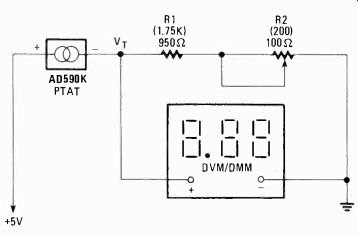
FIG. 1--SCHEMATIC DIAGRAM of Proportional-To-Absolute Temperature (PTAT)
probe circuit used to provide an analog output current proportional to
Kelvin and Rankine temperature scales. Values in parentheses are for Rankine
measurements.
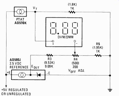
FIG. 2--SCHEMATIC DIAGRAM OF TEMP-SENSOR circuit with conversion from Kelvin-to-Celsius
(Rankine-to-Fahrenheit) temperature scales. Values in parentheses are
for Rankine-to Fahrenheit measurements.
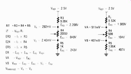
FIG. 3--EQUATIONS REQUIRED TO RECALCULATE resistances values for networks
in Fig. 2.
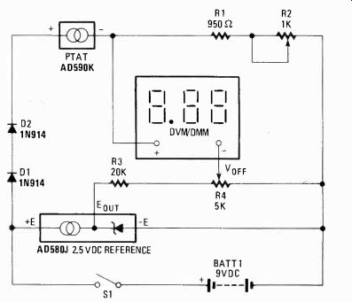
FIG. 4--AN ALTERNATE VARIABLE Temp-Sensor hookup which provides for a wide
range of adjustment. D1 and D2 are added to reduce thermal effects and
power-dissipation caused power supply rated in excess of 5 VDC.
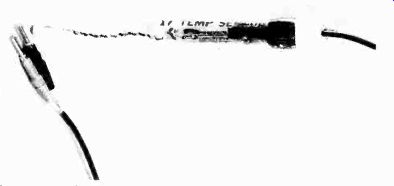
-------- THE AUTHOR'S PROTOTYPE TEMP-SENSOR unit is shown here.
The unit is housed in a glass thermometer case, but a plastic gravy serving
syringe can do the job. Just remove the rubber bulb. The syringe is available
in most Woolco stores.
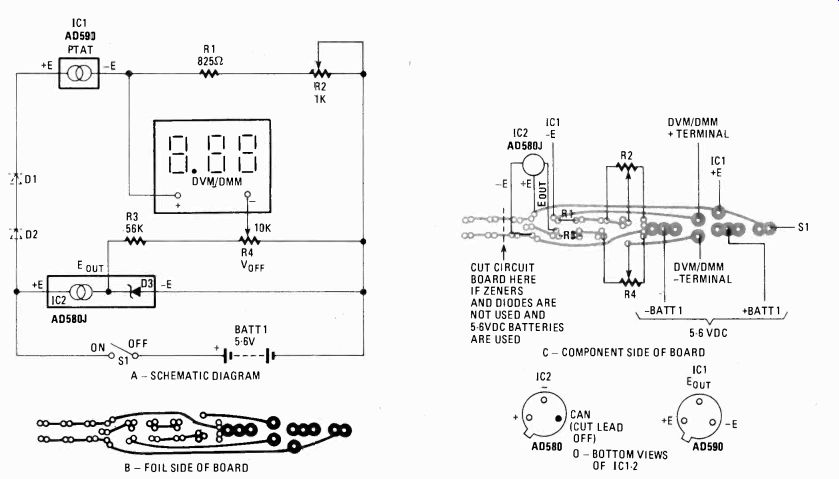

FIG. 5--The TEMP-SENSOR with all its various hookups are shown in a above.
The printed-circuit board (b) is designed for one of several Temp-Sensor
circuits you wish to assemble. Use no sockets; hard-wire throughout.
Keep components relatively close together to minimize thermocouple and
lead resistance effects.
-----------
PARTS LIST (See Fig. 5)
RESISTORS
5% film, zero or very low T.C. R1-825 ohms R2-1000 ohms, trimmer potentiometer, 10-15 turns R3-56,000 ohms R4-10,000 ohms, trimmer potentiometer, 10-15 turns SEMICONDUCTORS IC1-AD590K, see text IC2-AD590, see text D1, D2-1N914 D3-2.5 volt, 100 mA Zener
MISCELLANEOUS
S1-SPST toggle switch
BATT1-5-6 volt mercury or lithium battery
Printed-circuit board, solder, wire, etc.
Note: Not all these parts are necessary depending upon the circuit you are using. See Figs. 1, 2, 4, and 5.
AVAILABILITY
The following is available from ETC Company. P.O. Box 29278, Denver, CO 80229.
A complete set of parts to build a ±2% temp-probe, including AD590K IC and circuit board, less battery, for $21.00. Include $3.50 to cover postage and handling anywhere in the continental U.S. Electronic Technical Consultants reserves the right to discontinue products or change prices.
----------
Putting it all together
In Fig. 1, the AD590K temperature transducer provides a current that is directly proportional to absolute temperature value at a rate of 1 µA/°K. The output current develops a voltage determined by RI and R2 in series. Thus, giving that a current of 1µA/°K will flow through R1 and R2, when the series combination is trimmed to approximately 1000 ohms, 1mV/°K will be developed across the resistors. The trimming is required, because the AD590K has an absolute error of ±5.5% C maximum without a calibration adjustment and only a ± 2.0° C maximum error when properly adjusted. In any case, a DVM or DMM placed across R1 and R2, on its milli-Volt scale, would read temperature in °K, such that Vt = (R1 + R2) (1µA/°K). Now from the equation in Table 2, where R = 9/5K or 1.8K, it follows, that if we make the series combination of R1 + R2 = 1.8K, the 1µA/°K output of the AD590K would develop 1.8 mV/°K for a direct conversion to a Rankine temperature scale output.
Also, in Fig. 2, for an output proportional to the Celsius temperature scale, we apply equation C = K-273, where subtracting or offsetting V, = 1 mV/°K by 273 mV will give us a scale factor of 1 mV/°C. The AD580J provides us with a stable 2.5 volt DC reference and resistors R3, R4, and R5 gives an adjustable Vat--from approximately 243 mV to 292 mV for the resistive values shown. However, the manufacturer's sample values shown may be reworked with the aid of Fig. 3. More on this in a moment.
For an output proportional to the Fahrenheit temperature scale, from equation K = C +273 and from equation C = 5/9 (F-32), we may substitute one into the other, yielding F = 1.8K-460. Therefore, subtracting or offsetting V, = 1.8 mV/°K by 460 mV will give a scale factor of 1 mV/°F. Again, the AD580J provides us with a stable 2.5-volt DC reference and resistors R3, R4, and R5 gives an adjustable offset voltage, Voff, from approximately 407 mV to 511 mV for the resistive values shown.
In Fig. 2, the Vt trimmer in Fig. 1, was eliminated, because of the adjustment range offered by R4. Also, note that the values of the resistive trimmers in Figs. 1 and 2 are purposely kept small. Therefore, even a standard trimmer with a poor temperature coefficient (TC), will cause a minimal amount of accuracy drift due to mechanical vibration or thermal effects when used with more stable fixed resistors. In order to maintain long-term stability use stable film, wirewound, or chip resistors, with a small value of trim resistance or with high value trimmer potentiometers, use a multi-turn trimmer pot with a TC in the range of ± 50ppm.
But, you don't have to stay with the values shown in Fig. 2. Fig. 3 shows how to recalculate the values used for R3, R4, and R5 in Fig. 2, so you might make good use of some junk-box parts. Also, Fig. 4 offers another alternative, where multi-turn trimmer pots with low TC's are employed. The operation of the circuit in Fig. 4 is basically the same as that in Fig. 2; however, a 9-volt battery, B 1, has been added to supply power, with diodes D1 and D2 added to reduce thermal effects and probe power dissipation. Further, since R2 and R4 can be adjusted over a wide range, this configuration can be used to give a proportional output in °C, °F, °K, and °R. Construction hints All the circuits may easily be breadboarded, but for best results, the IC's should not be set in sockets, if possible, to avoid contact resistance problems at low currents and voltages. All components should be located relatively close to one another to minimize thermocouple and lead resistance effects, however, that is typically not so much of a problem, as with LM134 series devices. To maintain stability, follow the suggestions outlined above. There is usually no need to use shielded cable from the probe to DVM or DMM for moderately long cable runs. And kits of all parts for the Temp-Sensor are also available. Refer to the Parts List. Fig. 5 gives all the details necessary to build Temp-Sensor using the etched printed-circuit board made available by the author. The board can be used to hook any of the Temp-Sensor schematic diagrams illustrated in this article.
Calibration
The Temp-Sensor may be calibrated from a single set point, because of the linear output characteristics of the AD590K. To make a temperature trim adjustment, use several styrofoam containers placed one inside the other, filled with water and crushed ice. The mixture should be stirred, there should be just enough water to fill the voids created by the ice, and the mix must be allowed to stabilize for 15 minutes, allowing it to approach 0° C (32° F). (An old thermos jug is excellent, but it cannot be stirred. Instead, rotate the container to slosh the mixture about. The thermos thin walls break easily.) Now, with the temp-sensor leads insulated, immerse it into the center of the mixture and adjust the temperature trimmer potentiometer. For °C calibration, a DV.M or DMM on its milli-Volt scale should read 0 mV, and for °F calibration, the readout should read 32.0 mV. Also, calibration for °K or °R readouts would be handled in much the same way.
The AD590K temperature transducer has an absolute error with trim adjustments of ± 2.0° C maximum, when properly adjusted, and a nonlinearity of ± 0.5° C maximum. However, at the time when this article was written, a less expensive AD590J and more expensive AD590L were also available.
The AD590J can be trimmed to within ± 3.0° C max, with a nonlinearity of ± 1.5° C, so if you don't need a lot of accuracy, you might save yourself a few bucks by considering it. On the other hand, since electronics components usually get cheaper with time, the price on the AD590L's might drop; but they generally aren't worth any extra cost for most test-bench applications. Also, it should be pointed out that without a temperature trim adjustment, absolute error for the AD590J, AD590K, and AD590L are listed as ± 10.0°C, ± 5.5° C, and ± 3.0° C max, respectively. Therefore, to hold accuracy, you must trim them as indicated in the text; however, actual resistance network values may be altered to suit your needs.
When checking the temperature of an object, as opposed to a gas or liquid, such as a heat sink, transformer, power transistor etc., a heat-conductive grease (transistor grease) will provide effective heat transfer. The Temp-Sensor can be used around live circuits to test component heating; but the Temp-Sensor has a ± 200V isolation voltage rating, which may limit its use around high-voltage power supplies. Normal air pressure is assumed to be 760 mm pressure, and a change of 27.6 mm (slightly over 0.1 inch of mercury) will change the boiling point by one degree. If you are fussy, check a basic college first-year lab text book for interpolation details for spot corrections. Variations from fair temperature to stormy weather often involves a barometric change of 25 mm and more. Your local weather bureau usually announces barometric pressure on the hour.
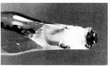
--- ANALOG DEVICES' TWO TERMINAL IC temperature transducer, AD590 is
held at the probe's tip with some R-V cement. Use a little heat-conducting
grease on the metal cap when making contact with surface and components.
For air and fluid measurements, just wait a moment or two for the IC to stabilize to the media's temperature.