By AL E. MANDE
Find the matching pair of wires in any cable or harness easily by letting your ears do the listening!
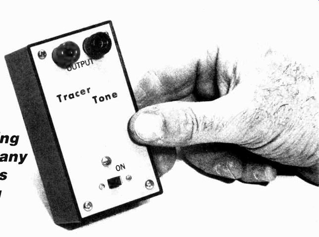
EVER WATCH A LONE TELEPHONE INSTALLER OR AN ELECTRICAL wireman unscramble pairs from a multi-wire cable? Without anyone to assist him, he somehow manages to trace the correct pair from "out in the street" to your home; often crossing through several wiring boxes, junctions and other cables where a color coded pair at one end bears no relationship to the pair at the other end.
The key to the wireman's success is often a raucous tone generator whose signal stands out from all the other beeps, whistles, and computer modem squeals likely to be found on audio or telephone circuits. He hooks the generator to a pair (two wires twisted about themselves) on one end of the cable and then searches for the same pair, or a connecting pair with a handset or headphones on the other end. Wiremen working on unknown circuits often prefer highly distorted tones that "spill" easily from one pair to another (that's crosstalk), which tells them quickly if they are at least in the general area of the correct pair, or for that matter, testing the correct cable.
Using spare parts which you are likely to have, you can build our Tracer Tone, a raucous tone generator that does almost the same thing as the "pro" signal generator.
Tracer Tone is an audio oscillator that produces a raucous tone in the area of approximately 800 to 1000 Hz. It is powered by an ordinary transistor-radio 9-volt battery. The current drain is nominally 2 mA, so even with heavy use the battery should last almost its shelf life.
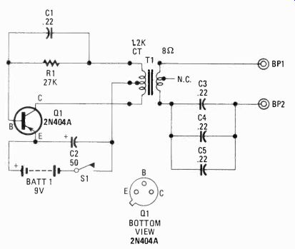
FIG. 1. SCHEMATIC DIAGRAM FOR TRACER TONE consists of so few parts that
the average experimenter may have all the elements in his junk box except
possibly for the transformer.
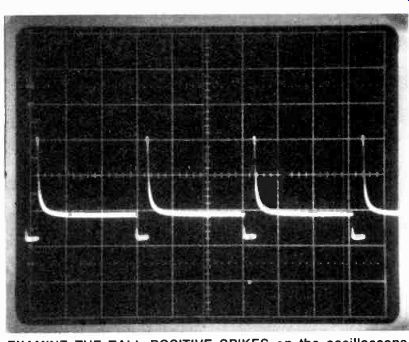
----------- EXAMINE THE TALL POSITIVE SPIKES on the oscilloscope screen developed by Tracer Tone. Those spikes are very rich in harmonics, as are the long and short pulses of an unbalanced squarewave. Your unit's tone will be distinctive.
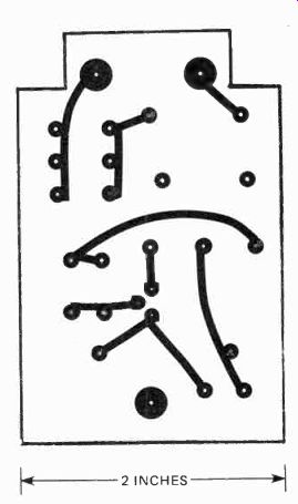
FIG. 2. PRINTED- CIRCUIT BOARD FOIL-UP diagram is simpler than the schematic
diagram. If you chose to use a perfboard, point-to-point wiring can be completed
by a novice.
PARTS LIST
R1--27,000-ohms, 1/2 watt, 10% resistor
C1-0.22-µF, 100 VDC capacitor, see text
C2-50-µF electrolytic, 15 VDC capacitor
C3, C4, C5--0.22-µF, 100 VDC, capacitor, see text
Q1--2N404A, PNP transistor
T1-miniature output transformer, 1200-ohm C.T. primary, 8-ohm secondary, Calectro
D1-724 or equal, see text
S1-SPST slide switch
BATT 1-9-volt battery, type 2U6
BP1, BP2-insulated binding posts
Battery holder, cabinet, PC materials, hardware, solder, etc.
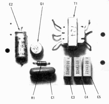
----- COMPLETED PRINTED-BOARD ASSEMBLY prior to mounting inside
the box of Tracer Tone. The two large holes at right are for the binding
posts, and the remaining hole is for the mounting screw. Slip a few washers
or a small spacer between the board and front panel under this screw
so that the board mounts parallel to the front panel. Check for shorts between
the underside of the board and the metal front panel.
Inside the circuit
As you can see from the schematic diagram (Fig. 1) the circuit is simple. In fact, except for the component values the project might possibly be a sine-wave oscillator. However, if you refer to the photograph, which is made directly from an oscilloscope's CRT, you will notice that the waveform is a highly distorted square wave with some spikes, producing a raucous sound easily distinguished from the usual signals that might appear on an audio or telephone cable. The waveform-which is distorted by design-is determined by the circuit's component values, so don't make any changes that are not recommended here if you want the device to work as described.
Also, note the unusual output circuit, which has a total series-capacitance value of nominally 0.66-µF, provided by three parallel-connected 0.22-µF capacitors--C3, C4, C5.
(Parallel 0.22-µF capacitors are used because it's a common value that's easy to locate; 0.6-µF is not a common value.)
Capacitors C3, C4, and C5 provide protection against a short circuit on the cable pair which would disable the oscillator, causing the battery current to increase from nominally 2 mA to more than 25 mA. The volume level is extra loud regardless of the type of headphone used as a monitor. You can use inexpensive "experimenter" type headphones, a single headphone, a lineman's handset, or a handset receiver salvaged from an old phone. Even high fidelity-type headphones can be used.
Construction
Tracer Tone is assembled on a printed-circuit board that fits (along with the battery) inside a plastic experimenter's box measuring approximately 4 x 2 1/16 x 1 5/8-inches. A full-scale template of the printed-circuit board is provided.
See Fig. 2. Two covers of the PC board are cut away to fit around the panel mounting projections inside the cabinet.
The board is also "short"-not the size of the front panel--to allow a miniature slide-type power switch to be mounted on the panel rather than on the PC board, which makes for a lot easier assembly.
The specified 2N404A transistor is a PNP type. The transistor is available for about 15 cents on the surplus market, if you don't happen to have one around. Feel free to substitute just as long as the hfe of the transistor you use is in the range of about 100-150. Don't substitute a super-high-gain transistor-the project won't work because the component values will be wrong for a high-gain transistor. You can even substitute an NPN transistor if you reverse the polarity of both battery B1 and capacitor C2.
Transformer T1 must be essentially the type specified, having a 1200-ohm, center-tapped primary winding and an 8-ohm secondary winding. The T1 used in this project also has its secondary tapped at 3.2 ohms, whose leads are cut short. The specified T1 is a GC Electronics type D1-724. It is also available under regional brands, such as Saxton, which also use the "724" as a part number (i.e., Saxton EA-724). The large solder pads in the copper foil pattern are the mounting screw locations. See Fig. 2. The two pads at one end will fit directly over binding posts BP 1 and BP2, with the connections between the PC foils and the posts made automatically when the mounting nuts are tightened. Since the pads on the PC board must contact the binding post hardware (for good electrical contact,) make certain the pads are sufficiently large, with a generous copper area remaining after the mounting hole is drilled through the pad.
The mounting holes for T1 's "ears" (the mounting lugs) should be a snug fit; generally a #57 drill bit is perfect. But, transformer dimensions do vary slightly, so check yours before you drill the holes (indicated by the two smaller, unconnected pads). Prepare the leads of T1 before it is mounted on the PC board. If you have used our template for your PC board, cut each lead to 1-inch, strip about' 0.25-inch of insulation off the end, twist the wires, and tin. Install the transformer by slipping the "ears" through the holes in the PC board and then bending them over by pressing the "ears" down with pliers or a screwdriver. Don't attempt to fold the "ears" with long-nose pliers; you get a loose mounting that way.
The pitch of the output tone is determined by capacitor C1. If you want to raise the frequency of the tone, reduce the value of C1; try 0.1 µF. There's no sense in making the pitch lower; that is because the lower frequency might not be reproduced with adequate volume by inexpensive headphones or receivers.
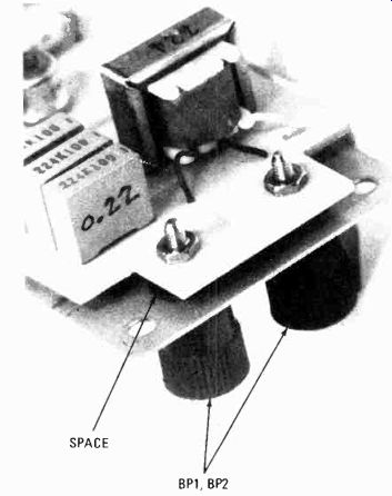
----- HERE'S A VIEW OF THE BOARD, SUPPORTED by the binding
posts above the metal front panel of the plastic box. Check the space
under the board as indicated in the photo and likewise under the screw mount
at the other end. If wires and leads were cut close to the board, there
should be no shorts at all.
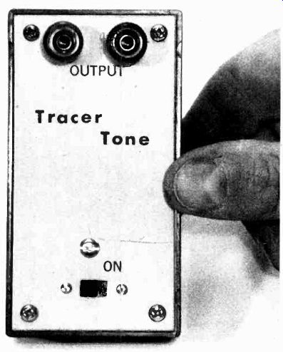
------ TRACER TONE ALL WIRED AND ASSEMBLED is ready for its
first assignment with the toughest of wire harness or cable. If you wish,
add an LED indicator and LED current-limiting resistor to the circuit so
that you'll know when the switch is on. The intent is not to extend battery
life, but to indicate to the wireman that the tone is being generated, and
being pumped into the cable.
Final assembly
Using the PC board as a template, mark the panel for power-switch Si and the output binding posts (BP1 and BP2). The post markings must be exact, because the PC board will drop directly over the binding posts. See photo.
Keep in mind that both posts are insulated from the metal front panel, so allow for the insulating shoulder washers.
Install both binding posts. Check with an ohmmeter to be certain that neither post is shorted to the panel. Secure each post to the panel with a single mounting nut (usually two are provided). Place a lockwasher on each post and then drop the board over the post, securing the board to the posts with the second nut provided with each post. Use a lockwasher here if desired.
Leave the board's mounting nuts loose and look to see how far the board is spaced off the metal panel. See photo. Use a spacer or a stack of washers of approximately the same thickness between the board and the panel at the third mounting screw. (The PC board must be spaced off the panel to prevent the foils from shorting to the panel.) After the PC board is installed, look between the board and the panel to make certain that no wires or solder lumps are shorting to the panel. If it seems to be "too close to judge," place a few strips of plastic tape on the panel to insulate the panel from the PC connections.
Using Tracer Tone
Connect the output to a pair of signal wires, or one wire and a ground, and search on the other end for the tone using some form of headphones or handset. If you can't hear the tone directly, listen carefully to several wires for crosstalk. Move the headphones from wire to wire, or pair to pair. Eventually you will hit the right wire(s). - SP