AMAZON multi-meters discounts AMAZON oscilloscope discounts
Introduction
This simple amplifier can be built by anyone who is able to solder reasonably well. It doesn't require any setting up and, provided our instructions are followed exactly, will work very well. The circuit diagram is included for the benefit of our more advanced readers, but it is not needed in the construction process. Please practice your soldering before you start, and don't use a printed circuit board (PCB) until you are confident that your soldering is up to scratch.
The amplifier can be used with other projects; it will provide plenty of sound from the MW Radio or from the Morse Sounder projects. It will usually be built into other pieces of equipment, so a box is not supplied with the kit. There is no reason why it shouldn't be put into a box and used as a general-purpose amplifier to help test other projects.
The components
Before you start, you should check that you have all the components to hand. A list and some helpful hints are given below.
1. PCB. The plain side is the component side and the soldered side is the track side. Figure 1 shows the track side full size. Make the PCB from the pattern given in Figure 1. Otherwise, build the circuit on a matrix board.
2. Three resistors. Locate the gold or silver band around the resistor, and turn the resistor until this band is to the right. There are three colored bands at the left-hand end of the resistor. Find the resistor whose colors are YELLOW, VIOLET, RED, and look at the resistor color code chart which you will find in Section 7. From this, you will see that YELLOW indicates the value 4, VIOLET the value 7, and RED the value 2. The first two colors represent real numbers, and the last value is the number of zeros (noughts) which go after the two numbers. So, the value is 47 with two zeros, i.e. 4700 ohms. In this way, the resistor colored BROWN, GREY, BROWN has a value of 180 ohms, and the last one, BROWN, RED, GREEN, has a value of 1 200 000 ohms. The ohm (often written as the Greek letter omega (Ω)) is the unit of resistance. If you do not yet feel confident in identifying resistors by their colors, use the Resistor Color Codes given in Section 7.
3. Four capacitors. The two small 'beads' are tantalum capacitors and will be marked 4.7uF or 4_7, with a '+' above one lead. A tubular capacitor with wires coming from each end should be marked 220uF, with one end marked '+' or '-'. This is called an axial capacitor because the wires lie on the axis of the cylinder. This is in contrast to the final capacitor, where both wires emerge from the same end. This is a radial capacitor, and will be marked 47uF. Again, one lead will be marked '+' or '-'. Capacitors marked like this are said to be polarized, and it is vital that these are placed on the PCB the right way round, so take notice of those signs!
4. Two diodes. These are tiny glass cylinders with a band around one end, and may be marked 1N4148; this is their type number. Like polarized capacitors, they must be put on the PCB the correct way round!

Figure 1 The toil pattern of the PCB - looking from the track side
5. Three transistors. One should be a BC548 (or a BC182), the other two should be BC558 (or BC212).
6. One volume control with internal switch.
7. One loudspeaker. This is quite fragile - don't let anything press against the cone.
8. One PP3 battery clip with red and black leads.
Putting it together
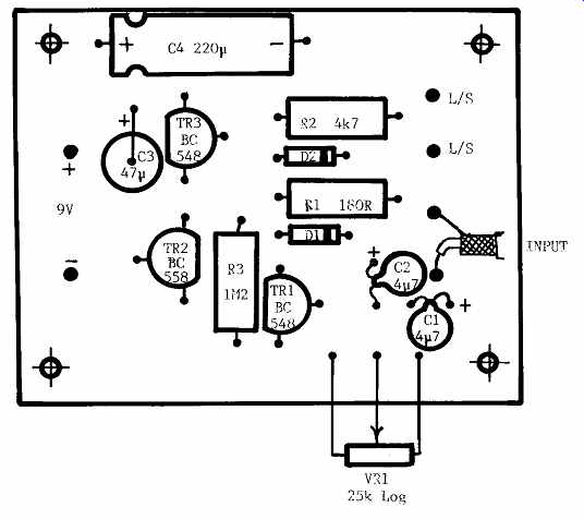
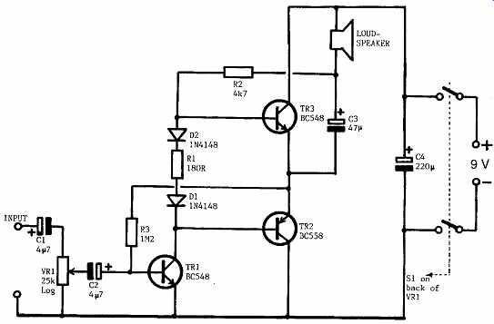
Lay the PCB on a flat, clean surface with the track side downwards. It is always useful to compare the layout with the circuit diagram, given here in Figure 3. Although you can't see it, the D-I-Y Radio sign should be at the top. Compare the hole positions with those shown in Figure 2. Bend the resistor wires at right angles to their bodies so that they fit cleanly into the holes in the PCB. Push each resistor towards the board so that it lies flat on the board. Then supporting each one, turn the board over and splay out the wires just enough to prevent the resistor falling out. Then, solder each wire to its pad on the PCB, and cut off the excess wire. When you have more confidence, you can cut of the excess wire before soldering; it often makes a tidier joint.

Figure 2 Positions of the components on the printed circuit board (PCB)
Now fit the four capacitors. Each must be connected the right way round, so look at each component, match it up with the diagram of Figure 2, bend its wires carefully and repeat the soldering process you performed with the resistors, making sure that the components are close to the board and not up on stilts! Fit the two diodes the correct way round, and solder then as quickly as you can -- they don't like to be fried! Mount the transistors about 5mm above the PCB. Make sure the correct transistors are in the correct places, and that the flats on the bodies match up with those shown in Figure 2.
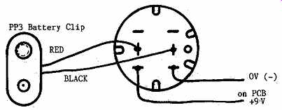
Mount the volume control so that the spindle comes out from the front of the board. Use a piece of red insulated wire to the pad marked + on the PCB, and a black piece to the pad marked -, and solder these to the tags on the back of the control, as shown in Figure 4. Connect the two leads from the battery clip to the other tags on the switch; Figure 4 will help you. Finally, use two pieces of insulated wire about 100mm long, twisted together, to connect the loudspeaker to the PCB.

Figure 3 The amplifier's circuit diagram

Figure 4 Connections to switch on back of VR1
Box clever!
If you wish to put the amplifier into a box, there is no problem; almost any box that is big enough will do. All that is needed is one hole big enough to accept the bush of the volume control; the PCB will be supported by the volume control. The prototype was not fitted into a box, but mounted on an odd piece of aluminum, bent into an L-shape and screwed on to a wooden base. The loudspeaker was mounted on the aluminum panel by two small pieces of aluminum with 3mm holes drilled in them, which acted as clips around the edge of the speaker. Drill a few holes in the panel in the position of the speaker to let the sound get out! Your input signal can be connected to the amplifier with two short pieces of wire, but if the connection needs to be long, use screened cable, with the braid connected as shown in Figure 2.
If you decide to use a different loudspeaker, make sure that its impedance (the resistance value marked on the back of the magnet) is at least 35 ohms.
Anything lower may damage TR2 and TR3, and will certainly run down your battery very quickly. You will be surprised at the uses you can find for this little amplifier!
======
Parts list:
Resistors: all 0.25 watt, 5% tolerance
R1 180 ohms (Ω)
R2 4.7 kilohms (kΩ)
R3 1.2 megohms (MΩ)
VR1 25 kilohms (kΩ) log with DPST switch
Capacitors: all rated at 25V minimum
C1, C2 4.7 microfarads (uF)
C3 47 microfarads (uF)
C4 220 microfarads (uF)
Semiconductors
TR1, TR3 BC548 npn
TR2 BC558 pnp
D1, D2 1N4148
Additional items
PCB Speaker >35 ohms
PP3 battery clip and battery