AMAZON multi-meters discounts AMAZON oscilloscope discounts
BASIC DVM
A typical digital multimeter was shown in Figure 1-2. it had a single rotary selector switch that not only selected whether the meter was to be used as a de voltmeter, de ammeter, ac voltmeter, or ohmmeter, but selected the full-scale range of the measurement as well. Another digital multimeter is shown in Figure 2-1. Like the one in Figure 1-2 it has a digital display, an ON-OFF switch, test jacks to accept test leads, a measurement function selection, and a full-scale range selection. It differs from the meter in Figure 1-2 in that it has two selector switches. One is for the measurement function, and the other for the full-scale range. It also measures ac current as well as voltage, while the meter in Figure 1-2 only measured ac voltage.
Comparison to Analog Meters
Unlike the analog meter that has a needle deflecting along a scale, each of these digital multimeters, as is the case for all digital multimeters, has a digital display. The measurement value is shown in both cases displayed as a number with four digits. On the lowest full-scale range, the measurement is read on the display to an accuracy of three decimal places.
Unlike the analog meter, digital multitesters have an ON-OFF power switch.
They contain electronic circuits to produce their measurement value rather than an electromechanical meter movement. As a result, they need internal batteries to supply power for the electronics as well as an energy source to supply current for resistance measurements when the meter is used as an ohmmeter. The ON-OFF switch connects the power source to the circuits. Like the analog meter, the digital multitesters have range and function selector switches and jacks to accept test leads.
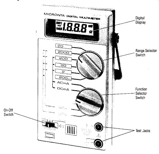
Figure 2-1. Digital Multimeter
DVM Characteristics
Several important characteristics result from the fact that digital multitesters are electronic. One characteristic is that they are basically voltmeters, and when used as ammeters or ohmmeters, the circuit arrangement is such that the DVM is used as a voltmeter. A second characteristic is that the DVM has a high internal resistance on all functional ranges. As will be shown in Section 3, having a high internal resistance is a very desirable characteristic because circuit loading is usually negligible when using a DVM. The third and fourth characteristics are due to the digital display. Because the display is digital there is no parallax reading error, or error due to interpolation between scale marks as on an analog meter. Because the display is digital, the conversion accuracy is within ± one digit on any of the scales used. The accuracy due to the display remains constant over all ranges and doesn't vary. As a result, overall accuracies of DVMs are typically 0.05% to 1.5% as compared to 3-4% for analog meters.
A fifth characteristic relates to the special functions that are available. An audio tone that sounds when measuring circuit continuity is a common example. A special check for semiconductor junctions is another. The meter in Figure 1-2 has the semiconductor junction test, while the meter in Figure 2-1 has both special functions.
HOW A DVM WORKS
A block diagram of a typical digital voltmeter is shown in Figure 2-2. Either de or ac voltages can be measured. Let's look at measuring a de voltage first.
The test probes measure the de voltage, bring it into the DVM through a signal conditioner, and couple it to a circuit called an analog to digital or A to D (A/D) converter. The A/D converter accepts a voltage and changes it to a digital code that represents the magnitude of the voltage. The digital code is used to generate the numerical digits that show the measured value in the digital display.
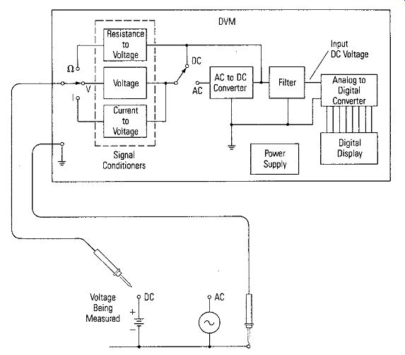
Figure 2-2. Block Diagram of a Basic Digital Voltmeter
Digital Display
An easy way to understand how a DVM works is to begin at the display. Figure 2-3a shows a common way to display a numerical digit. A 7-segment array of elements is used to form the digits. The array elements may be vacuum fluorescent, electroluminescent, or plasma display elements. But very common displays for portable DVMs used in the laboratory or service shop are light emitting diodes (LEDs) or liquid crystal displays (LCDs). Liquid crystal displays use very little power, but must have ambient light or back illumination to operate the display. LED displays use much more power, but are much brighter and not easily washed out in bright sunlight.
As shown in Figure 2-3a (which is a typical LED display schematic), a power source is connected to each LED segment, and each LED segment is excited by passing current through it. In the example shown, the segments necessary to display a numeral 2 are grounded and current through them causes the segments to emit light. The table shown in Figure 2-3b lists the segments that must be excited to display any of the numerals from 0 to 9. As shown in the example of Figure 2-3a, a decoder establishes the proper segments that must be grounded. The decoder has an input digital code that represents the numeral required.
• BCD Codes
A very common code used in digital systems to represent numerals is a 4-bit binary coded decimal (BCD) code. The BCD code for the numerals from 0 to 9 is shown in Figure 2-3b. This code, if fed into the decoder of Figure 2-3a, will cause the decoder to ground the proper segments of the digit display to display the proper numeral for the table of Figure 2-3b.
Analog to Digital (A/D) Conversion
Now that we know how the BCD codes provide the input to display the numerals, let's find out how the codes are generated in the A/D converter. A block diagram is shown in Figure 2-4. The table shows the BCD code that is output for each of the four digits when a de voltage between 0 and 2 volts (1. 999 volts) is applied at the input. The resolution of the DVM is one millivolt, which means that a new 4-digit BCD code is generated for each change in one millivolt of the input voltage. Figure 2-4 does not show each one millivolt 4-digit code, but lists the codes that would be generated for the four digits for each one tenth of a volt. In addition, it shows some special example values (0.001, 0.578, 1.234, 1.667 and 1.999) to help understand what the A/D converter output is like. There is a separate 4-digit BCD code for each one millivolt, but, for simplicity, they are not all included in Figure 2-4.
If the input voltage to the A/D converter is 1.234 volts, the four-digit BCD code that would be generated at the output would be 0001 0010 0011 0100 as shown. Each of the 4-bit BCD codes representing a digit is coupled to a decoder, like the one shown in Figure 2-3a, and the proper numeral displayed for the respective digit.
Individual logic gates in the A/D converter control the decimal point. If a logic 1 level is output, the decimal point will be ON. As the scales change, the decimal point energized changes.
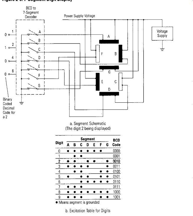
Figure 2-3. 7-Segment Digit Display
a. Segment Schematic (The digit 2 being displayed)
b. Excitation Table for Digits
The display techniques and the outputs of the A/D converter shown in Figure 2-3 and Figure 2-4 are not the only way a DVM can produce the conversion and display.
There are scanning techniques and multiplexing techniques so that the digit codes are transferred in sequence along fewer bus lines, but the more direct way was chosen to make it easier to illustrate and explain the basic concepts.
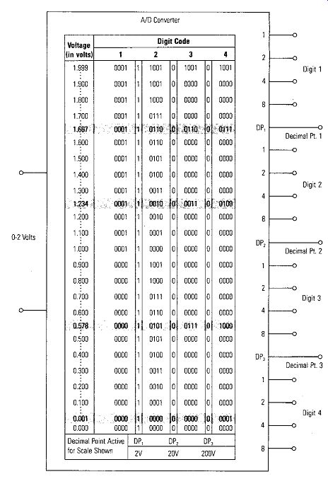
Figure 2-4. A/D Converter with 0-2 Volts Input and 4 Digit Output Codes
THE A/D CONVERSION PROCESS
There are a number of techniques used to perform the actual conversion process.
Staircase integrating, continuous balance, successive approximations, dual-slope, voltage-to-frequency converters are the names of some of them. We do not have space to cover all of these, so we will pick the staircase and the dual-slope converter because these demonstrate the basic concepts the best.
Staircase Converter
Figure 2-5 shows the block diagram of a staircase converter. It consists of a comparator, a clock gate G, a clock generator, a binary counter, and a digital to analog converter. The output is coupled to a digital display. The digital to analog converter does the opposite of the analog to digital converter. It takes the digital code output from the stages of the binary counter and converts it to an analog voltage. Each time the binary counter increases its count by one, the output voltage VO increases by a millivolt. VO is one input to the comparator; the input voltage V_in is the other input to the comparator.
• V_o Not Equal to V_IN
When the input voltage V_IN is first applied to be measured, V0 is zero, and the output of the comparator is at a 1 logic level because V0 if not equal to V_in.
Since the comparator 1 output is an input to the AND clock gate G, the clock signal appearing on the other G input will appear on the gate output and feed into the binary counter.
The binary counter counts the clock pulses, and through the D/A converter begins to increase V0 by 1 millivolt per count. Thus, the name staircase converter.
• V_o Equal to V_iN
When V0 is equal to V_in, the comparator output drops to a 0 logic level, turns off the clock pulses through G, which stops the count and holds V0 equal to V_in.
The digital code at the counter is converted to the necessary code for display of the numerals that represents the value of the voltage V_in
Note that it takes time t1 to reach the point where V_o = V_in; therefore, measurements can be done only at a maximum rate.
Dual-Slope Converter
A block diagram of a dual-slope A/D converter is shown in Figure 2-6. It consists of an operational amplifier, A, connected as an integrator, a comparator, a logic gate (G) for gating the clock signal, a counter for counting clock pulses, a reference voltage, and control logic circuitry. The output feeds to a digital display.
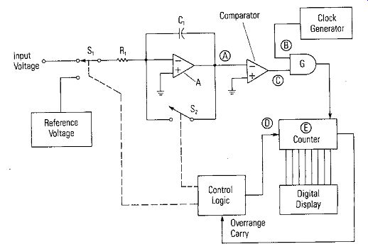
Figure 2-6. Dual-Slope A/D Converter
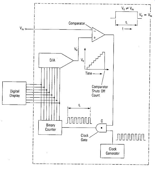
Figure 2-5. Staircase A/D Converter
As with the staircase converter, the magnitude of the input voltage measured is determined by the number of clock pulses counted. The resultant counter code is then converted to the appropriate code to display the proper digits on the digital display.
The number of pulses counted is determined by a start count control signal (D) in Figure 2-6 which allows the counter to start counting, and a comparator output signal (C) which stops counting by gating off the clock pulses. The timing is shown in Figure 2-7.
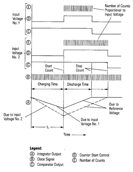
Figure 2-7. Dual-Slope Converter Operation ---- Legend:
-- Integrator Output -- Counter Start Control
-- Clock Signal -- Number of Counts
-- Comparator Output
• Basic Operation
The basic concept of the operation is as follows: S, is a switch that shorts out C, so that there initially is no charge on C,. When a measurement is made, S, is open, and S, is connected to the input voltage for a period of time t, shown in Figure 2-7. In time t,, capacitor C, charges at a constant rate and to a magnitude of voltage determined by the input voltage. At the end oft,, S, is switched to a reference voltage that is opposite in polarity to the input voltage. This reference voltage discharges capacitor C, at a constant rate. The time that it takes to discharge C back to the initial zero level (and just a few millivolts more because the comparator output must switch states) is proportional to the input voltage magnitude. The charging and discharging curves for two different input voltages are shown in Figure 2-7.
When the discharge time starts (at the end oft,), the start control (D) starts the counter. At the end of the discharge time, the comparator output (C) goes to a low logic level, turns off gate G, and stops the counter. As shown in Figure 2-7 for two different input voltages, the number of clock pulses counted is proportional to the input voltage, and as mentioned previously, the counter digital code is decoded to display the proper digits on the digital display.
AC MEASUREMENTS
The ND converter is designed to accept a de voltage and convert it to a digital code so the corresponding digits can be displayed. Referring back to Figure 2-2, we see that if the input to be measured is an ac voltage, a circuit in the DVM converts the ac voltage to a de voltage, filters it and couples it to the ND converter. It isn't absolutely necessary, but the de voltage also passes through the filter in case there are some noise spikes on the input de voltage.
SIGNAL CONDITIONERS
Because the A/D converter always needs an input de voltage, all uses of the DVM as a voltmeter, ammeter, or ohmmeter requires that signal conditioners be used to convert the measured quantity into a de voltage. The three types of conditioners are shown in Figure 2-2. Let's look at the voltage conditioner first.
Voltage Conditioner
Since the range of voltage that the A/D converter can handle is limited by design--zero to two volts in our example--measured voltages greater than two volts will need to be attenuated, and voltages less than one-third to one-fifth of a volt will need to be amplified. Therefore, the voltage conditioner, a shown in Figure 2-8, is made up of a voltage divider to provide the attenuation and an operational amplifier to provide the amplification. There are five voltage ranges - 0. 2V, 2V, 20V, 200V and 2000V. The gain of the operational amplifier is set by the equation
A - _RF
- R, where R, is the input resistance. The minus sign means that the output signal is 180° out of phase from the input signal. RF and R, (made up due to R,, R3 and R,) are chosen so that A equals one on the 2V range. With unity gain for the amplifier (A = 1), the input voltage is reproduced directly at the amplifier output and coupled to the A/D converter. On the 20V, 200V, and 2000V range, R3 and R, are chosen such that the gain of the amplifier is unity again, just as for the 2V range (RF does not change). The ratio of R,, R, and R,; to R, is set so that with 20 volts, 200 volts, and 2000 volts, respectively on the input, the input voltage to the amplifier will be 2 volts. For the 0. 2V range, R, is chosen so the gain of the amplifier is ten.
The voltage conditioner will work equally well for de and ac voltage measurements over the frequency range specified for the DVM as long as the stray capacitance in the circuitry is kept to a minimum. Of course, the ac voltage at the output of the signal conditioner must be converted back to de before it is coupled to the A/D converter.
AC to DC Conversion
Many VOMs, multitesters and DVMs that have rectifier type circuits have scales that are calibrated in RMS values for ac measurements, but actually are measuring the average value of the input voltage and are depending on the voltage to be a sine wave. These instruments are in error if the input voltage has some other shape than a sine wave.
There are DVMs that are manufactured that measure the true RMS value of input voltages regardless of the shape of the waveform. They measure the de and ac component of the input waveforms; therefore, the measured value is the heating power of an ac voltage that is equivalent to the heating power of a de voltage equal to the RMS value--the definition of an RMS voltage. Check the specifications of a DVM that you are using to determine if it measures true RMS voltages. If it does not, be wary of the measurement if the input voltage is not a sine wave or if it has a de component.
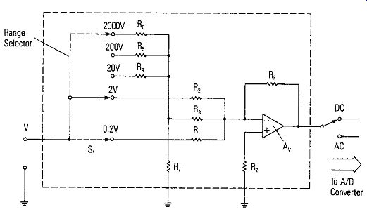
Figure 2-8. Voltage Conditioner
Current Conditioners
The signal conditioning circuit for measuring current is shown in Figure 2-9. The current conditioner changes the current to be measured into a voltage by passing the unknown current through a precision resistance (R,, R,, R, or R,) and measuring the voltage developed across the resistor. The range switch determines the resistor used for each range. When the proper current range is selected, the proper resistance is selected so that the voltage out of t~e current conditioner will be within the range required by the ND converter. The resistors used are a special type of high power precision resistor used as current shunts.
The position of the AC/DC switch determines the route the voltage output from the current conditioner takes to reach the input of the ND converter. A high current range, such as 10 amps, usually is measured using a special input jack to which a special resistor is connected. An operational amplifier with a fixed gain prevents loading of the current sensing resistors by the ND converter.
Resistance Conditioners
The basic circuit for the signal conditioner that the DVM uses for resistance measurements is shown in Figure 2-10a. The voltage V and the resistance R, form a constant current source for the unknown resistor. A constant current through a given resistor will produce a set voltage drop. For example, if the constant current is 1 milliampere (0.001A) through a 1000 ohm resistor, the voltage drop across the 1000 ohm resistor is 1 volt. That's exactly what the DVM does to measure resistance, it measures the voltage across an unknown resistance when there is a known constant current through it. The voltage source, the series resistance, and the voltage range are changed as the full-scale range of resistance to be measured by the DVM is changed.
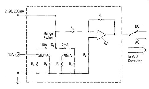
Figure 2-9. Current Conditioner
An alternate circuit found in some popular DVMs is shown in Figure 2-10b. It uses a ratio method to measure the value of the unknown resistor. If an unknown resistor Rx is placed in series with a known reference resistor RR across a known voltage source Vs, the ratio of the voltage drop across the unknown resistor, Vx, to the voltage across the reference resistor, VR, is equal to the ratio of Rx to RR. This is expressed by the equation:
Rx Vx RR= VR
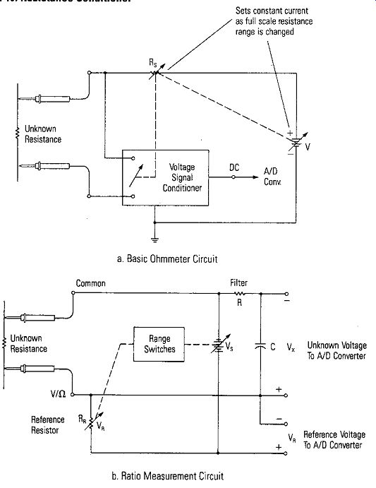
Figure 2-10. Resistance Conditioner --- a. Basic Ohmmeter Circuit ; b. Ratio
Measurement Circuit Sets constant current as full scale resistance range
is changed
Rearranging gives the value of Rx in terms of the known reference resistor and the voltage ratio.
v, Rx~ RRVR
Extra circuits are designed into the A/D converter so it can be used to measure the voltage ratio Vx/VR and calculate the unknown resistance, R,. RR and Vs are changed for different resistance ranges, but are known values for each measurement calculation.
• Hi-Lo Ranges
The test circuits are carefully designed so that the power dissipated in the device under test is limited to safe values. Some DVMs allow the selection of a Hi/LO measurement range. These ranges allow the user to select the voltage drop across the component under test at full scale to be either 2 volts on the Hi range or 0.1 volts on the LO range. The LO range allows in-circuit resistor testing without forward biasing diodes or transistor junctions that may be in parallel with the resistor. The Hi ranges allow deliberate testing of semiconductor junctions to determine if they are forward or reverse biased and their respective junction resistances.
BASIC CHARACTERISTICS OF 0 VMS
Besides the characteristics of accuracy and internal resistance (input impedance) that VOMs have, the DVM have specifications for resolution, response time, protection, and burden voltage. The most unique specifications are the ones that define the digital display and the full-scale range.
Digits of the DVM Display
A strange term has developed when specifying a DVM. It concerns the digital display. The term "half-digit" is used to describe the display capability of the DVM and the reading beyond full-scale that it can display. This is called over-ranging.
If a DVM is classified as a 3½ digit DVM, it means that the full-scale reading is displayed in three digits and that the digit to the left of the 3 digits for full-scale is restricted in range. For example, 0. 999 would be the full-scale reading when the DVM is measuring one volt on the 1 volt range. The½ digit specification means that the DVM can display a measurement up to 1.999. The digit to the left of the three full-scale digits is restricted to a one. A 4½ digit DVM would have a capability to read a value to 19999. A 3¾ digit DVM would have the capability to read a value as high as 3999. Therefore, the½ or¾ digit specifies the over-ranging that the DVM can read when set on a particular range.
Full-Scale Range
Range is specified in one of two ways: (1) a full-scale range with usable overrange capabilities specified as a percentage, typically 100%; or (2) full scale specified as the maximum possible reading encompassing all usable ranges, often 1.999. For example, a DVM may be specified as having 1 volt full scale with 100% overrange, thus indicating useful operations to 2 volts; or the same DVM may be simply specified as having a 2 volt full scale.
Some ranges may not be used to full scale. For example, the higher voltage ranges may be limited because of the voltage breakdown of internal components. A DVM with a 1999 volt full scale range may not be used to read over 1000 volts because divider resistors cannot withstand over 1000 volts breakdown. The capability may be even lower on AC because of peak voltages.
• Overranging
Overranging was instituted to take full advantage of the upper limits of a range. It also provides better accuracy at the top of a range. In other words, over-ranging allows a DVM to measure voltage values above the normal range switch transfer points without the necessity of having to change ranges. It allows the meter to keep the same resolution for values near the transfer points.
The extent to which the overrange is possible is expressed in terms of the percentage of the full-scale range. Overranging from 5-300% is available depending upon the make and model of the DVM.
Accuracy and Resolution
Simple accuracy specifications are given as "plus/minus percentage of full scale, plus/ minus one digit." The "plus/minus one digit" portion of the specification is caused by an error in the digital counting circuit. The "plus/minus percentage of full scale" includes ranging and A/D conversion errors.
The "plus/minus one digit" also relates to the resolution of the DVM. The resolution of an instrument is directly limited by the number of digits in the display. A 3½ digit DVM has a resolution of one part in 2,000 or 0.05% which means that it can resolve a measurement of 1999 millivolts down to 1 millivolt. A 4 ½ digit instrument has a resolution of one part in 20,000, or 0.005%. A 2½ or a 3 digit DVM is considered approximately equivalent to a good VOM multitester as far as accuracy and resolution are concerned. Accuracy generally lies between 0.5% and 1.5% and resolution to 0.5%. The 3½ and 4½ meters generally have accuracy one order of magnitude higher; that is, between 0. 5% and 0. 05% with 0. 05% resolution. A resolution and accuracy of this amount will generally suffice for most service work today. A 4½ digit, 5½ digit DVM generally indicate an accuracy of 0.05% and better with resolution of 0.005%. These are indeed considered laboratory instruments. They usually are specified with a "plus/minus percent of reading, plus/ minus percent of full scale, plus/minus one digit" specification. They also may have specifications that qualify the accuracy at temperatures other that 25°C. A DVM has essentially the same accuracy on ac that it does on de voltage measurements while the accuracy of an analog meter is most assuredly less accurate on the ac voltage measurements. Accuracy will also depend upon the frequency response or bandwidth of the DVM, and on the ac waveshape when the meter does not measure true RMS voltages.
Input Impedance
DVMs have an input impedance of at least one megohm and more commonly 10 megohms. This holds true on dc measurements and on ac measurements over the frequency range specified for the DVM.
Response Time
Response time is the number of seconds required for the instrument to settle to its rated accuracy. The response time consists of two factors: (1) the basic cycle rate of the A/D converter; and (2) the time required to charge capacitances in the input circuit. Instead of response time, some manufacturers simply give a number of conversions per second.
Protection Meter protection circuits prevent accidental damage to the DVM. The protection circuit allows the instrument to absorb a reasonable amount of abuse without affecting its performance. The specification of input protection indicates the amount of voltage overload which may be applied to any function or range without damage.
A separate de limit may be indicated to cover input coupling capacitor breakdown.
Overloads from sources outside the specified frequency range of the instrument may not have as great a protection range. The current measuring circuitry is usually protected by a fast-blowing fuse in series with the input lead.
Ammeter Errors Due to Burden Voltage
When a meter is placed in series with a circuit to measure current, an error caused by the voltage drop across the meter is due to the meter and its current shunts and any protective fuses that are connected in series. This voltage drop is called a burden voltage. The full scale burden voltages for the instrument are usually very low-0.3 volts for low ranges and from 0. 5 to 0. 9 volts for the high current ranges. These voltage drops, of course, can affect the accuracy of a current measurement if the current source is un-regulated and the resistance of the current meter represents a significant part (1/1000) of the source resistance. This burden voltage error can be minimized by selecting the highest current range that provides the required resolution. Some manufacturers specify "voltage burden," which is the maximum voltage drop across the meter input terminals caused by full-scale current. Other manufacturers specify series resistance. Either is adequate as long as the value is specified for each current range.
Displays
We have already mentioned LED and LCD displays. The light-emitting diode (LED) has been one of the most popular displays in use with DVMs because of its brightness, excellent contrast and low cost. Other displays have historically been 10 character neon displays (NIXIE) and the 7-segment neon display. The disadvantages of these displays are higher cost combined with the need for a high-voltage power supply. Neon, as well as fluorescent displays, tend to generate slight RF interference noise. The liquid crystal display (LCD) is becoming very popular because of its very low power drain and decreasing cost. The newer types do not wash out in bright sunlight. However, a disadvantage is that many of them will freeze at fairly moderate temperatures and become completely useless.
SPECIAL FEATURES
Auto Ranging Auto ranging automatically adjusts the meter's measuring circuits to the correct voltage, current or resistance ranges. One technique is for the DVM to start on the lowest range and automatically move to the next higher range when auto range takes place. A special feature of some auto range DVMs (Radio Shack No. 22-193 shown in Figure 2-11) is the RANGE HOLD position. This is useful when a series of measurements are made within a specific range. The power switch is set to the RANGE HOLD position while the first measured value is still on the display. This allows the AUTO RANGE function to skip immediately to the range on hold.
If the upper limit of the range being held is exceeded, the meter produces a series of beeps and displays a flashing 1 indicating an overflow error. Turning the power switch to the ON position releases the RANGE HOLD.
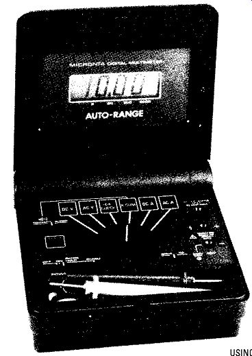
Figure 2-11. Auto-Range DVM Auto Polarity
The automatic polarity feature further reduces measurement error and possible instrument damage because of overload due to a voltage of reverse polarity.
A + or - activated on the digital display indicates the polarity and eliminates the need for a POLARITY switch setting, or reversing leads.
Hold That Reading!
Many digital multitesters have a HOLD feature that is operated remotely by means of a special HOLD button included on one of the test leads. It is particularly useful when making measurements in a difficult area because readings can be captured and held and read when convenient.
In some DVMs, the hold signal sets an internal latch that captures the data.
When the A/D gets to the point in its cycle where data is to be displayed, the state of the internal latch is sampled. New data is not transferred while the latch is in the hold state. In other DVMs, the hold feature stops the instrument clock. The last value displayed on the LCD remains displayed until the ground is removed from the input terminal.
Conductance Measurements
Some meters display the reciprocal of resistance; that is, a conductance measurement. The controls and connections for conduction measurements are the same as for resistance. The output, however, is displayed in siemens, the reciprocal of resistance (previously called mhos).
Semiconductor Testing
A DIODE CHECK or SEMICONDUCTOR CHECK function appears on some DVMs. Most DVMs have an ohmmeter voltage of greater than 1.5 volts. Thus, continuity for most diodes and transistors in the forward bias direction may be checked.
Some DVMs have a special feature when in the DIODE CHECK position that displays a voltage value which is essentially the forward bias voltage of the PN junction.
Audible Continuity Test
Often DVMs have an audible continuity function. With the DVM set to measure resistance and the CONTINUITY switch activated, when the probes are touched together the DVM emits an audible sound. This electronic sound is used to look for short circuits or for tracing for an open circuit. Any time the continuity circuit resistance is less than a minimum amount, usually 200 or 300 ohms, the DVM emits an audible sound when the circuit is complete.
Now that we know the basic concepts of VOMs and DVMs let's move on to find out how to make measurements.