by ELLIOT S. KANTER
The best solution to any problem is often the simplest one. Here are some easy-to-use ideas that really work.
A SHORT TIME AGO, I RECEIVED A CALL from a sales engineer who I'd helped before with certain technical problems.
This time he had a serious problem that demanded an immediate resolution, as human lives hung in the balance. It seemed that around four in the after noon each day, the telemetry units in his hospital's coronary-care unit were "clobbered" by brief but overpowering interference.
As you might suspect, the tiny radio transmitters (Fig. 1) that were attached to the patients are low-power (power output is about 1 microwatt) and they transmit in the VHF portion of the radio spectrum. Not being able to drive the 150 miles or so to the hospital, I reasoned that there was a pattern (i.e. specific time each day) and that only the telemetry equipment was being interfered with. About a week or so before, I had posed a question to my class of BMET's (Biomedical Equipment Technicians), that asked them to determine a harmonic relationship between a CB transmitter and patient telemetry, and if a harmonic relationship could be identified, what specific telemetry frequencies (there are about eighty) would be affected.
I pulled out my list of calculations, and determined that the telemetry-transmitter frequency was the same as the seventh harmonic of a CB frequency. A quick call to the engineer with the suggestion that he take a walk around the area immediately surrounding the hospital resulted in both identification of the source and a cure. It appears that a nearby citizen was operating an illegal linear amplifier or "kicker." After a few words of explanation, he disconnected the linear and the interference was gone.
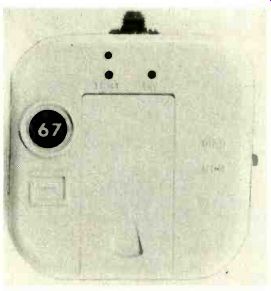
FIG. 1—MEDICAL TELEMETRY transmitter.
Some of those transmitters have power outputs on the order of a microwatt and a range of about 250 feet.

FIG. 2--THIS simple RF sniffer can also be used with a digital voltmeter.
Naturally, the majority of CB users do not operate illegally, but if you do come across a problem like that one, why not stop a minute and determine what frequencies could (not necessarily would) have a harmonic relationship that might cause problems. Remember, it is not the properly-operated RF source that will cause the problem, but rather one improperly used or adjusted that can frequently be at the root of a problem.
Staying with low-powered RF sources for a while longer, I found that I needed an easy and cheap method of being certain that one of those small telemetry transmitters was really putting out RF. Again, I was faced with the fact that one particular model didn't even put out a full microwatt, and a frequency counter was a clear case of over-kill.
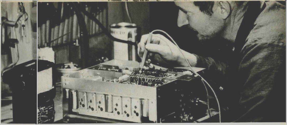
What did evolve is shown in Fig. 2, a simple, cheap, and easy-to-build RF sniffer, in a shielded metal case.
If you are an "old timer," you will recall the circuit as an add-on RF probe for use with a VTVM. It can be used with digital voltmeters as well. If you deal with devices like medical telemetry equipment, you might want to replace the probe and ground leads with either plugs or jacks to match the input (which is also the output) of the telemetry transmitter. Shielded cable is a must (RG-58/U or RG174/U) from the probe to the VTVM. The device detects RF and displays it as a DC voltage. While that will not give you a calibrated indication of the power output, it will show you when RF output is there.
PC board component replacement Usually, changing a resistor, capacitor, or diode on a PC board isn't too difficult or time consuming. All you have to do is unsolder the old part, remove it, make certain the PC board holes are clear, insert the new component, resolder and clip off the excess leads. I know you are saying that's nothing new and, in fact, those five steps are just what you always do... right? WRONG! Consider a service request I had from a client: She (the head nurse) wanted all twenty of her heart-rate alarms modified for a longer delay before going off in the high-rate mode. That meant that I would have to alter a time constant determined by a resistor and capacitor on each of twenty modules. It was obvious that it would be simpler to change the 22K resistor to 39K than to match a capacitor, but I didn't especially relish all of that soldering and unsoldering.
Hence the five-easy-step method illustrated in Fig. 3.
1. Take long-nose pliers and crush the resistor (or diode or capacitor). You might also need side cutters to do the job, but the object is to destroy the component, leaving only the leads.
2. Clean off the wires, and blow or brush away any residue from step one from the PC board.
3. Use your long-nose pliers and bend both of the leads upward so that they will form two posts.
4. Make a loop in each end of the replacement component (I did that before I arrived on site) and slip the replacement component over the two posts prepared in step three. Be sure to observe polarity indications.
5. Solder both connections.
Since you can pre-form the replacement components, you have cut your work at least in half and besides, you have done a neat, professional job without risking heat damage to the PC board traces, which is more than I can say for the conventional (still five steps) method of replacing components. Just be sure that you use a well-tinned iron and only enough heat and solder to do the job (right.
Versatile heat sink Like most hobbyists and technicians, I build some equipment myself, either from scratch or in kit form. No matter how careful you are, that old demon-Murphy, of Murphy's Law-tends to rear his ugly head and make junk out of what should have been a lovely, neat project. Most problems seem to be heat-related and take place while following the instructions that state: "Flip the board full of components over and solder each connection." While modern components are a great deal less heat sensitive than older transistors such as CK722's heat can, and often does, alter specifications. Besides, there nothing as upsetting as a fully loaded PC board sliding across the table X'op as you try to solder.
The solution is to locate an ordinary kitchen sponge slightly larger than the PC board in question. You can throw caution to the wind and purchase one or more sponges at your local hardware or discount store. For less than two dollars, you should be able to acquire a collection of assorted man-made sponges which, when damp, will serve two distinct purposes. First, they will act as a slip-resistant PC board holder and second, they will function as a heatsink. If you are a non-believer, the first sizzle you hear while soldering will make a "true-believer" out of you. A bonus is that the PC board is elevated slightly for better access. That hissing will warn you that things are getting hot and will prevent component values from "shifting" due to excessive heating.
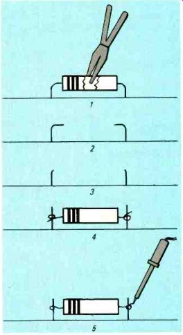
FIG. 3--FOLLOWING these five steps when you replace components on a PC
board will result in less work and a neater job.
Iron idler
There's nothing quite so frustrating as having to wait for your soldering iron to heat up from a dead start. Well, maybe there is something equally frustrating-replacing tips that have been rendered "inoperative" due to overheating. You might suggest the use of a soldering gun but remember, very few
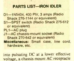
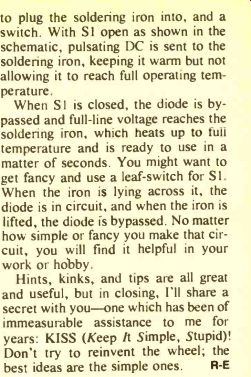
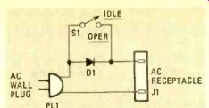
Fig. 4