Source: Radio Electronics--Electronic Experimenter's Handbook (1993)
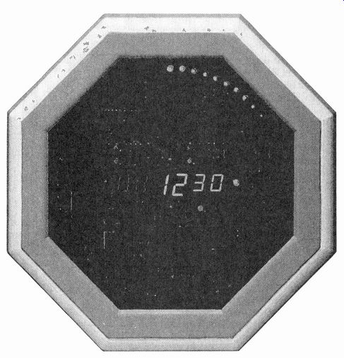
Build a digital clock that's way ahead of its time!
by LEON W. SCHMIDT
THE TECHNOLOGY TO PRODUCE low-cost digital clocks has existed for years. Unfortunately, the style in which these clocks have displayed the time has been mostly limited to four dig its (representing hours and minutes). Few digital clocks, if any, have taken full advantage of the great capabilities of to day's microprocessors to provide a more novel display... that is until the HyperClock.
The HyperClock has a custom-programmed micro-controller that generates all the signals necessary to display time in eight eye-catching (yet easily readable) modes. Among its features are the ability to simulate a sweep second hand with a ring of 60 LED's; it can graphically display the level of ocean tides; it has a "fading" display mode that causes the LED's to gradually change when updated; it has a hourly chime / alarm output; supports 50- or 60-Hz powerline operation; it has a battery backup; and an intelligent date display that knows the last day of each month. Let's take a look at those features in greater depth.
The digital display In four of the HyperClock's eight modes it can display time with a clever twist that those of you that grew up before the "dig ital-clock revolution" will appreciate. You may recall that it was fairly common for folks to speak of how many minutes it was till the next hour. For example, people would say "it's ten before five" rather than "it's four-fifty." Well, the HyperClock can actually "display" the time in that manner.
To help explain how that is done, take a look at Fig. 1-a; it shows the six seven-segment LED displays that are used to form the clock's digital display.
During the first 30 minutes of each hour, the two middle digits signify the hour and the right most digits indicate minutes past the hour (like most digital clocks), and the two digits on the left are blank. Figure 1-b shows how eleven fourteen (or literally " fourteen after eleven") would look in this mode.
However, once the clock advances to beyond half-past the hour, the right digits go blank, the middle display would increment to display the next hour, and the left two digits would indicate how many minutes are left until that hour. For example, if it was thirteen minutes to twelve (or 11:47), the display would look like Fig. 1-c. You could read that literally as " thirteen before twelve." On the hour, the clock just displays the hour, so the left and right minute displays remain blank (see the display for 12 o'clock shown in Fig. 1-d).
As mentioned earlier, there are 60 LED's arranged in a circle to display seconds or an approximation of the current tide level in your locale. The LED's act as a light chaser sweeping through the seconds of a minute. They can also show the relative tide level by moving from the 12 o'clock position at high tide to the 6 o'clock position at low tide. The timing of the tide-indicator mode is set to display two complete tide cycles in 24.51 hours just as it should.
(For more on this subject see the sidebar entitled "A Bit About Tides.") Fading-out the digits The HyperClock also differs from other clocks in how it up dates its display. In typical clocks, the display digits abruptly change as time passes.
However, in four of HyperClock's eight modes when a digit must be updated, the LED segments representing its old value are dimmed as the segments for the new value become brighter.
Likewise, each LED in the light chaser fades off rather than turns off. This animation is rather relaxing to watch.
These display effects are accomplished by a mixture of multiplexing and duty-cycle modulation. The seven-segment displays are all common-anode types, so each digit has its own anode-driver transistor. In typical multiplexed-display fashion, the cathodes of corresponding segments of each digit are connected together and share a common driver.
Like any other multiplexed display when the segment data for a digit is placed on the segment data lines, the anode driver for that digit is activated, and the seven-segment display lights to exhibit the appropriate digit. All the other digits are off at this time. After a short period of time (1.83 ms) the segments are turned off via the segment lines and the anode driver is de activated. The anode driver for the next digit is then activated, the segment data for that digit is placed on the segment lines, and the process continues until all the digits have been lit. Since the human eye is too slow to see the digits turn on and off, it appears as though they are all on simultaneously. Multiplexing the digits in this fashion reduces the number of pins on the microcontroller needed to control the LED displays.
HyperClock's fading effect is created by modulating the duty cycle of the segment enable signals. When a seven-segment display is enabled, the segment data lines spend part of the time in states corresponding to the current digit to be displayed, and the rest of the time in states corresponding to the next or "future" digit that will be displayed. Each time the digit is enabled, the duty cycle will favor the future-digit data more and more, until only the new digit is displayed, and the process re peats each time the display must be updated.
The microcontroller At the heart of the HyperClock is an Intel 8749 microcontroller.
It is programmed to perform a variety of functions, namely: display multiplexing, time keeping, receiving switch in put, coordinating the hour and alarm chime, and initiating a power-fail mode that permits the time-keeping functions to continue while blanking the display to conserve backup-battery power.
The 8749 has 2K of EPROM, 128 bytes of RAM, 24 I/O pins, a programmable 8-bit timer, and an interrupt-control structure.
The custom-program placed in the processor to create HyperClock's special effects extensively exercises all of the chip's features; Fig. 2 contains a simplified flow chart for the HyperClock program. The program is shown divided into two sections: an interrupt routine and a main loop.
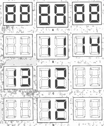
FIG. 1-HYPERCLOCK'S TIME DISPLAY (a) is unique in that it not only displays
time normally (b), but it can indicate minutes left to the next hour (c),
and blanks the minute displays on the hour (d).
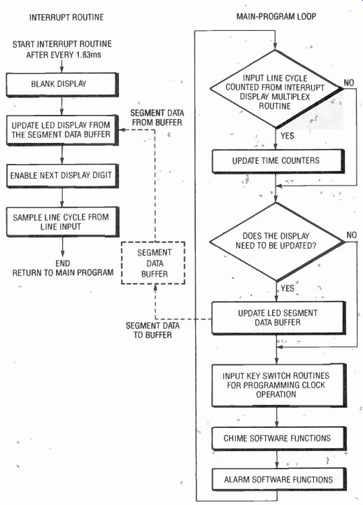
FIG. 2--HYPERCLOCK'S SOFTWARE can be broken down into two distinct code
segments: a clock-scheduled interrupt routine, and a main-program loop.
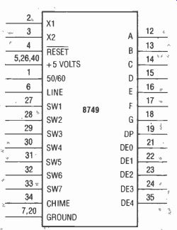
FIG. 3--THE PINS ON THE 8749 micro-controller are assigned various functions
by the HyperClock program.
The interrupt routine is mainly responsible for taking the segment data from the segment-data buffer in the micro-controller and placing it on the display-control lines in a multiplexed fashion. The interrupt that initiates the routine comes from the 8749's internal timer, which has been programmed to execute the interrupt every 1.83 ms. Using an interrupt-pro gram segment in this way al lows the display's fading effect to appear gradual because the process of updating the display occurs at regular intervals. This routine is also responsible for checking a powerline-frequency input on the microcontroller to determine if a powerline cycle has passed. If so, it informs the main loop of the program.
The main loop keeps track of the number of cycles that pass so it knows when to update the segment-data buffer or initiate the alarm or chime. If no powerline cycles are detected, the main loop assumes AC power has been terminated and puts the clock in power-fail mode. In that mode it shuts off the display and allows the microcontroller to "invisibly" keep track of time via a 6-MHz crystal. The main loop also processes input from the clock's switches (we'll talk more about that later).
For all that goes on inside the microcontroller, the functions assigned to its pins by the HyperClock program (see Fig. 3) are relatively easy to under stand. Let's take them one group at a time.
The pins labeled A through G and DP (pins 12-19) in Fig. 3 are the outputs for the display-segment data. They indirectly control the cathode drivers for the multiplexed display. Similarly, the outputs labeled DEO-DE4 (pins 21-24 and 35) control the anode drivers for the display via demultiplexer chips, which we'll discuss later.
The pins labeled S1-S7 (pins 27-34) are used as function-switch inputs. The switches connected to those inputs (DISPLAY MODE, DISPLAY DATE, DIS PLAY ALARM. INCREMENT HOUR/ MONTH/MODE, INCREMENT MINUTE/ DAY. SNOOZE/TIDE ADVANCE, and ALARM TOGGLE, respectively) activate various chip functions by grounding those pins. A complete explanation of the switches' functions will be presented later.
Low-going pulses from the pin labeled CHIME (pin 34) activate the chime circuit, which is composed of discrete components. The microcontroller triggers the chime circuit with a 12.8-ms wide low-going pulse at one-second intervals. When not in alarm mode, the chime signals the hour by chiming an appropriate number of times, and signals each half-hour by chiming once.
When the microcontroller is in the "alarm" mode, the chime circuitry is used as an alarm annunciator. In this mode the clock does not chime on the hour and half hour. That permits you to use the HyperClock as an alarm clock without the chimes disturbing you until the appointed time.
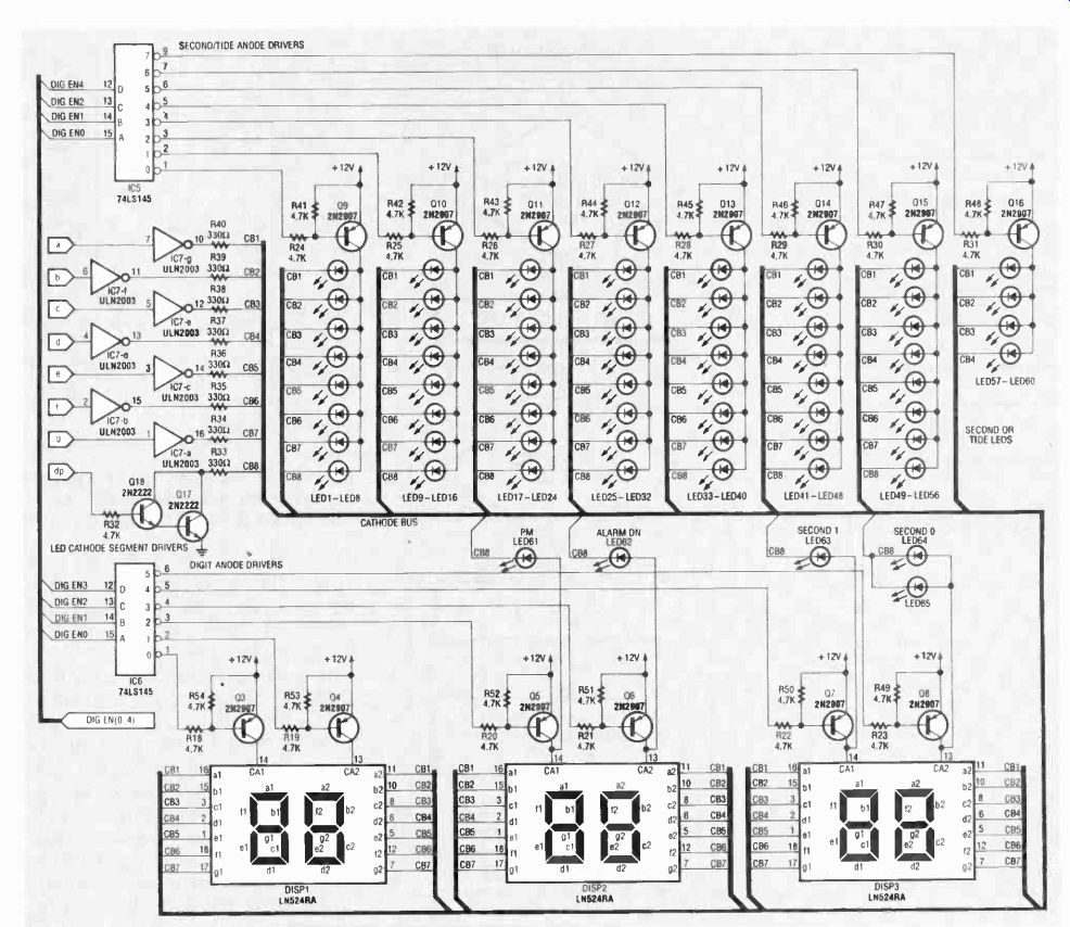
FIG. 4--THE HYPERCLOCK DISPLAY is controlled by only 13 data lines from
the microcontroller.
The LINE input (pin 6) is used by the IC to accept a 50- or 60-Hz square wave. The square wave is used for time keeping and to detect AC-power failure as mentioned earlier. The 50Hz/60Hz input (pin 1), tells the 8749 what frequency to expect at the line input. If pin 6 is low, the 8749 assumes the line signal is at 60 Hz, but if that pin is high the 8749 prepares for 50-Hz operation.
As its name implies, the RESET input (pin 4) initializes the microcontroller. A low at that input will erase all modes and settings previously entered.
The X1 and X2 inputs (pins 2 and 3) need to be connected to the 6-MHz crystal, XTAL1, mentioned previously. Last, but certainly not least, are the 5-volt power inputs (pins 5, 26, and 40) and the grounds (pins 7 and 20). Those inputs of course, are self explanatory.
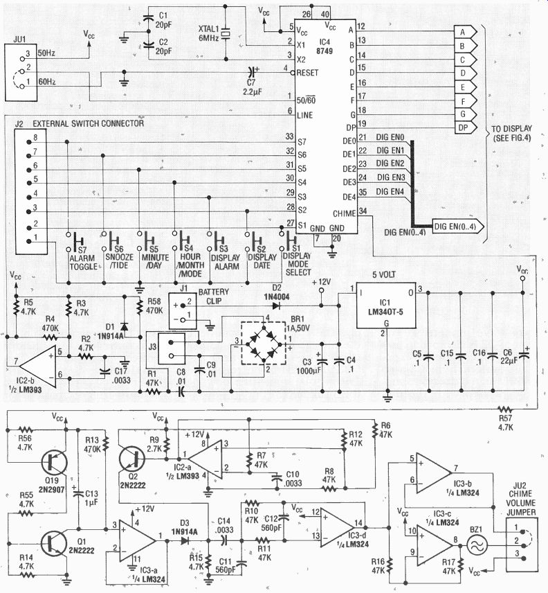
FIG. 5--THIS SCHEMATIC DIAGRAM FOR THE HYPERCLOCK circuit (less the display
components) shows the support circuitry required by the microcontroller.
The display circuit
While the microcontroller does a great deal, the HyperClock requires some additional circuitry to make it a complete timepiece. For example, the microcontroller cannot provide nearly enough current to drive the LED display. For that reason additional anode and cathode drivers were included in the design. They are shown along with the other display components in Fig. 4.
The control signals for the LED cathodes originate from the A-G and DP pins of the micro-controller. The A-G signals are sent to a ULN2003 buffer/driver (IC7) which contains seven high-current drivers. Each out put is capable of providing 500 mA of peak drive current. Since the ULN2003 contains only seven of the eight cathode drivers required, a Darlington driver was made out of two 2N2222 transistors to drive the DP line.
The DE0 through DE4 outputs generated by the micro-controller are decoded by two 74LS145 decoder/driver IC's (IC5 and IC6). Only one decoder output is driven low at any time.
Each 74LS145 output supplies current to a 2N2907 drive transistor that sources current for the anodes of a group of LED's or a display digit.
Note that there are additional LED's to provide an AM/PM indication (LED61), tell you if the alarm-mode is active (LED62), and provide a winking second display (LED63 to LED65).
That's all there is to the display circuit.
The remainder
The most noteworthy of the clock's remaining circuitry (shown in Fig. 5) is the chime circuit. When the micro-controller generates a low-going pulse on pin 34, it activates Q19. That transistor then provides sufficient current to drive Q1 into saturation.
With Q1 on, the negative side of C13 is effectively grounded, which causes it to charge. When Q1 is turned off, C13 discharges through a 470K resistor (R13).
The resistor/capacitor combination has a time constant of 0.47 seconds. The exponentially decaying signal produced by the discharge is buffered through a unity-gain amplifier (IC3-a) to a 1N914 diode (D3).
The cathode of D3 is connected to the output of a 50% duty cycle 5-kHz square-wave oscillator consisting of IC2-a, R7, C10, and Q2. Transistor Q2 serves to provide a dynamic pull-up for that oscillator since the LM393 is an open-collector type comparator. The 5-kHz square wave present at the emitter of Q2 is clamped in amplitude by the buffered exponential waveform from IC3-a, so the 5-kHz signal decays in amplitude in step with the discharge of C13.
The decaying 5-kHz signal is fed through C14 to a second-order low-pass filter tuned to approximately 5 kHz. The filter is composed of a LM324 op-amp (IC3-d), C11, C12, C14, R10, and R11. It removes the high-frequency components contained in the decaying square wave to smooth it out. From there the signal is passed to two more op-amps (1C3-b and IC3-c) that form a push-pull amplifier, which provides the piezo transducer with a 10-volt peak-to-peak drive signal.
While the output signal is not exactly a pure sine wave, the audible result sounds pretty much like a small bell. If you feel the chime is too loud, you can eliminate half of the push-pull amplifier by jumpering one side of the transducer to the 5-volt supply, which is available via JU2.
The entire circuit receives power from a 9-VAC wall-mount transformer. The 9-VAC supply is fed to a full-wave bridge rectifier and filtered by C3 to act as an unregulated 12-volt DC supply. The 12-volt supply powers the display circuitry, op-amps, the comparators, and an LM340-5 (IC1) 5-volt regulator.
The regulator in turn powers the 5-volt supply line.
If AC power is interrupted, a 9-volt battery connected to J1 sources current to the regulator to keep the HyperClock functioning. If you plan to unplug the clock for any length of time, the battery should be disconnected to conserve its life.
=====
PARTS LIST
All resistors are 1/4-watt, 5%, unless otherwise indicated.
R1, R6-R8, R10-R12, R16, R17 47,000 ohms
R2, R3, R5, R14, R15, R18-R32, R41-R57-4700 ohms R4, R13, R56--470,000 ohms
R9-2700 ohms R33-R40-330 ohms, 1/2-watt, 5%
Capacitors
C1, C2-20 pF ceramic C3-1000 uF, 16 volts, electrolytic C4, C5, C15, C16-0.1 ceramic C6-22 uF, 16 volts, electrolytic C7-2.2 pf, 16 volts, electrolytic C8, C9-0.01 ceramic C10, C14, C17-0.0033 uF, ceramic C11, C12-560 pF, ceramic C13-1 I.LF, 16 volts, tantalum
Semiconductors
IC1-LM340T-5 5-volt regulator IC2-LM393 dual-comparator IC3-LM324 quad-op-amp IC4-8749 microcontroller with HyperClock program IC5, IC6-74LS145 1-of-8 decoder/driver 1C7-ICLN2003 high-current driver D1, D3-1N914A diode D2-1N4001 diode Q1, Q2, Q17, Q18-2N2222 NPN transistor Q3-016, Q19-2N2907 PNP transistor BR1-1-amp, 50 volts P/V bridge rectifier DISP1, DISP3-Panasonic LN524RA or similar 7-segment display (for the smaller digits) DISP2-Panasonic LN526RA or similar 7-segment display (for the larger digit) LED1-LED65-light-emitting diodes Other components XTAL1-6-MHz crystal T1-9-VAC 500-mA wall-mount transformer BZ1-piezo transducer S1-S7-miniature momentary-contact pushbutton switch B1-9-volt battery
Miscellaneous: T-220 style heatsink, PC board or perforated construction board, battery clip, shorting blocks, solder, etc.
Note: The following items are available from SkiTronix, P.O. 9685, Spokane, WA 99209:
A pre-programmed HyperClock 8749 microcontroller with firmware license-$11.00.
An etched and drilled PC board-$25.00.
The foil pattern artwork suitable for conversion to film-$3.00.
Software on floppy disk--$5.00 postpaid
A complete kit of parts including the PC board, programmed 8749 IC, LED's, displays, electronic components, and the wall-mount transformer--$75.00.
A detailed drawing of the HyperClock wood case, will be supplied with all orders. Please include $4.00 for shipping and handling. Washington residents must include an additional 8.0% sales tax.
=====
A BIT ABOUT TIDES
Predicting the tides in any given locale is not a simple job. Tides are affected by many cyclic astronomical forces: the declination in the orbits of the moon and sun relative to a point on the Earth, and the local geography of the coast line in the area in which you live, to name a few.
HyperClock predicts the tidal levels from the most predominate of these forces, the moon. The moon requires 29.53 days to orbit Earth, and that combined with the 24-hour solar day causes a high and low tide in every 12 hour and 25.5 minute interval. HyperClock tracks the moons primary affect on the tide. You can find out about the level of local tides in your area from your newspaper or library. The information can be used to initially set the tide indication on your HyperClock to a low or high point. From then on the graphic display will be an aid in the determination of the relative level of the tides in your locality.
========
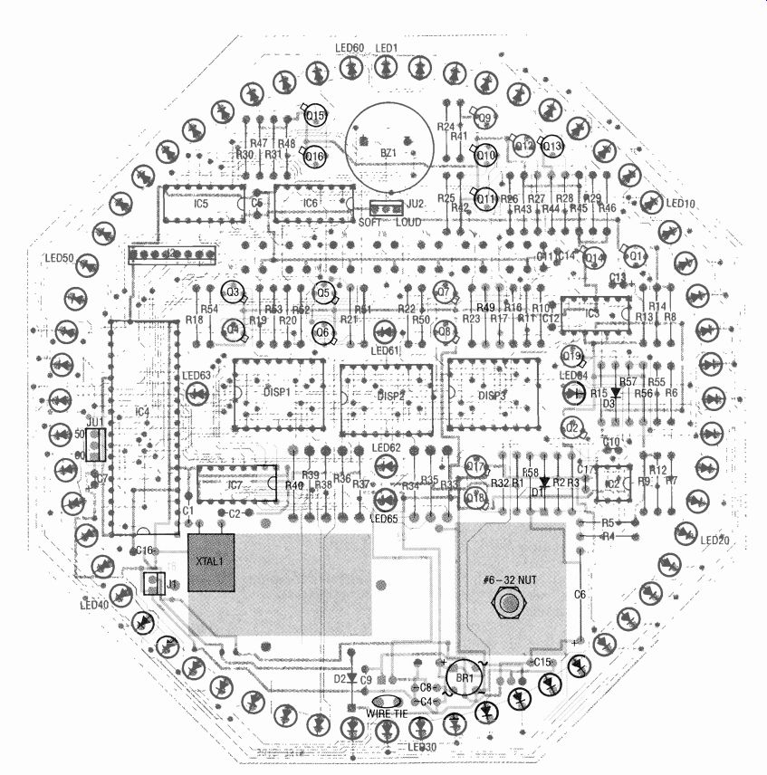
FIG. 6--DISPLAY-SIDE PARTS-PLACEMENT diagram can be used to locate most
of the HyperClock's components.
========
The line input (pin 6) of the microcontroller cannot be driven directly from the 12-VAC wall transformer. So the trans former signal is conditioned by a Schmitt-trigger circuit to generate a suitable square wave.
First the signal's amplitude is reduced by a voltage divider consisting of R1 and R58, and its positive excursions are limited to about 5 volts by Dl. The limited signal is then sent to the inverting input of the LM393 comparator. Positive feedback is applied to the comparator's non-inverting input by R4 to prevent it from generating false signals. The comparator drives the microcontroller's line input with the resulting square wave.
Construction In order to build a HyperClock, you'll need a programmed 8749 microcontroller.
A preprogrammed and tested microcontroller is available from the supplier mentioned in the parts list. The executable code to program an 8749 is available from the RE-BBS (516-293-2283, 1200/2400, 8N1), as a file called HYPER.HEX. The file is sup plied in Intel's Hex format, which is directly compatible with most EPROM programmers. The software is also avail able on floppy disk from the source mentioned in the parts list.
A 6.5- x 6.5-inch octagon-shaped PC board is also available from that supplier to help you assemble a HyperClock of your own. If you wish, you can make your own double-sided printed-circuit board from the foil patterns included in this article or using artwork from the supplier listed in the parts list.
Of course, you could even use a point-to-point wiring technique, so we'll discuss that briefly later on.
Figures 6 and 7 show the parts-placement diagrams for the HyperClock (6 shows the display side and 7 shows the solder side) for those of you that will use a PC board. All components, except for the wall-mount transformer, are shown mounted on the circuit board.
Note that the switches can be placed on either side of the board, depending on the cabinet you wish to place the clock in. There are some additional connector pads on the board so you can run wires to the switches should your cabinet design require that they be located off the PC board. Figure 8 shows a completed HyperClock board.
The design readily lends itself to many different project cases. However, make sure that the cabinet you choose has some openings in the back to allow a little cool air to flow around the clock's 5-volt regulator and heat sink. If you like the case used for the prototype, you can build one out of a length of wood molding as the author did.
The PC board was designed to work with many different dual-digit displays, so you don't necessarily have to restrict yourself to the Panasonic units mentioned in the parts list. Just make sure that whatever you use is a pin-for-pin same-size replacement. If you do use the recommended units, be sure to raise the two minute displays up from the board so that their viewing surfaces are flush with that of the hour display.
Lastly, the PC board provides some holes for wire ties to hold the 9-volt battery and the wall-mount transformer leads. You should take advantage of them.
Remember to install the 9-volt backup battery and connect JU1 and JU2 to select 50- or 60-Hz operation and the volume of the chime, respectively.
When you connect the clock to power it should come up at 12:30 AM and will be ready to accept the current time, alarm time, date, and the tide level if desired. If you run into any difficulty, you may find some of the troubleshooting tips provided in the following section useful. However, if all is well, you can proceed to the "operating" section to prepare the clock for use.
Point-to-point wiring Working with perforated construction board and point-to point wiring gives you the freedom to design your own display layout. One nice alternate de sign would be to place the 60 LED's in the form of a full cycle of a sine wave, especially if you set the clock to display the tide level.
An early prototype of the clock was built using wire wrap. Regardless of the wiring technique, you should invest in a large enough piece of perforated construction board (at least 6 x 6 inches) so that you can make your custom display with plenty of room to spare for all the sup port electronics.
Furthermore, when you are shopping for the hour and minute displays, select minute displays that are somehow distinctly different than the hour display. That will make the display more easily readable in the "minutes before the hour" mode.
It is also suggested that you don't place tilt,-'splay components on the same side of the board as the heatsink/regulator assembly, C3, and the 9-volt battery. Doing so would in crease the profile of the display side of the board, forcing you to place the LED lens at an un desirable distance from the display components.
Aside from those suggestions, layout is not critical, so if you observe good construction and wiring techniques you should not have any problem getting the clock to function. However, if you should encounter some difficulty, the following hints ought to help:
If no LED's are illuminated when you apply power, first check the unregulated supply for a minimum of 10 volts DC.
While only 2 to 3 volts of over head are required to operate the 5-volt regulator, at least 10 volts is required to drive the LED's sufficiently.
If the power-supply circuitry is okay, check the wiring around the LM393 (IC2) from the bridge rectifier and going to IC4 pin 6; the microcontroller looks at that line and if there is no line frequency at that input, the clock will shut down the LED drivers (as we explained earlier).
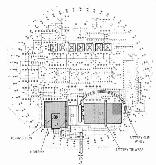
FIG. 7--THIS PARTS-PLACEMENT DIAGRAM should be used to position
the regulator, battery, a capacitor, and the switches.
Since most of the wiring in the clock runs between the LED drivers and the LED's, it is likely that you could have made an error in one or more of those connections. If you observe that any active LED segments do not form numbers, then you should check the connections from IC4 to IC7 and the corresponding connections to the cathodes of the LED displays. A mistake be tween IC4 to IC5 and IC6 will make the displayed digits and/ or seconds appear out of order.
An error in wiring from the out puts of the 74LS145's to the driver transistors, which connect to the LED anodes, will cause the same effect.
Operation The functions performed by S4 and S5 in the HyperClock depend on the state of the three display switches (S1 through S3). If none of the display switches are depressed, pressing S4 advances the current hour displayed and pressing S5 advances the minute display.
That is how you set the time.
Pressing and holding down S1 (the Display-Mode button) causes the clock to display the number of the current operating mode, which can be altered by pressing S4 (S5 will do nothing). The various operating modes and the features they support are listed in Table 1.
If you depress and hold switch S2 (the Display-Date button) the current month and day are displayed. With that switch de pressed, the month and day can be advanced by pressing S4 and S5, respectively.
Activating switch S3 will cause the clock to display the time the alarm is set for. By pressing S3 along with S4 you can alter the hour setting, and by pressing S3 and S5 simultaneously you can change the minute setting.
Moving on to the last two switches, the Alarm Toggle switch (S7) determines the state of the alarm and the hour chime of the clock. For example, on power-up the hour chime is enabled and the alarm is disabled. If S7 is pressed once, the alarm is turned on and the hour chime is disabled. Depressing the switch again will turn off both the alarm and the hourly chime.
The Snooze/Tide Switch (S6) has a dual purpose. If the HyperClock's alarm was armed and goes off, that button will silence the alarm for an additional ten minutes. You can forestall the alarm in this way as many times as you like. If the alarm is disabled, and the clock is in a mode that supports the tide-level display (modes 4 through 7), pressing S6 will advance the tide indication on the 60-LED display to set its position.
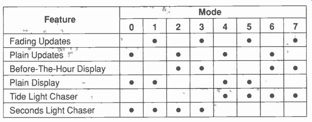
TABLE 1--MODES AND THEIR FEATURES
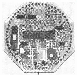
FIG. 8--A FINISHED HYPERCLOCK. The PC board makes assembly neat and straightforward.
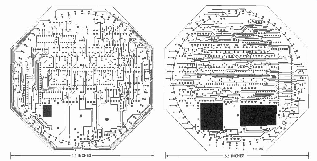
-------- THE
DISPLAY-SIDE FOIL PATTERN can be used to generate one side of the clock's
PC board. --------- THIS FOIL PATTERN can be used to generate the solder
side of the clock's PC board.