Source: Radio Electronics--Electronic Experimenter's Handbook (1993)
by T.L. PETRUZELLIS
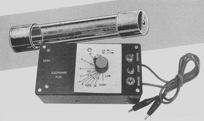
How do you troubleshoot power-related problems without blowing fuse after fuse? Just use our electronic fuse!
THE ELECTRONIC FUSE IS A sensitive fast-acting adjustable circuit breaker that will quickly become one of your most useful bench-top accessories. If you have been stumped by a faulty electronic circuit and consumed a number of costly or hard-to-locate fuses, you will appreciate this inexpensive circuit breaker.
All you have to do is connect the electronic fuse to the device under repair, and then adjust the current threshold control to the value you need anywhere from 1/20 to 10 amperes.
Additional applications for the electronic fuse include charging circuits for marine/mobile/air craft systems, as well as new circuit designs. The electronic circuit breaker could be used after the design of a new circuit to help choose the correct value fuse. The electronic circuit breaker is connected in place of the original fuse of the device under repair or test. If the breaker "trips," a red LED will light and power is cut off. When you're ready to continue, simply press the reset button.
==========
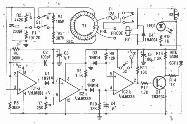
FIG. 1--THE ELECTRONIC FUSE is almost like an adjustable circuit breaker,
where you can adjust the trip point anywhere from 0.1 to 12 amps.
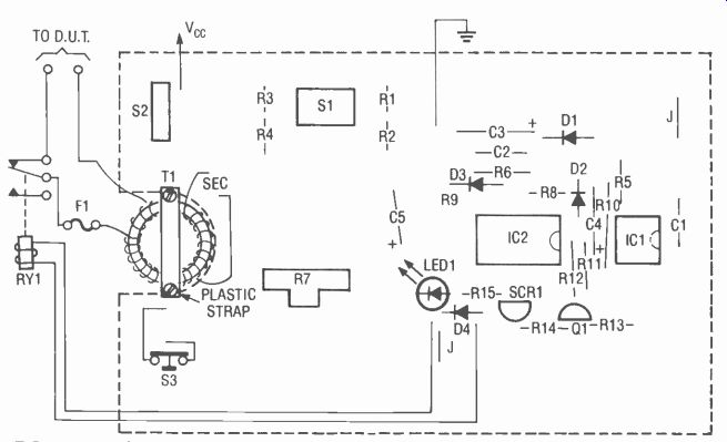
FIG. 2--PARTS PLACEMENT DIAGRAM. Because various controls are mounted directly
on the PC board, you may have to drill tiny pilot holes on the circuit board
in the center of each control location, place the unpopulated circuit board
directly on top of the case, and then transfer the holes before installing
the components on the board.
======
PARTS LIST
All resistors are 1/4-watt, 5%, un less otherwise noted.
R1-107,200 ohms, 1% R2-442,000 ohms, 1% R3-387,000 ohms, 1% R4-165,000 ohms, 1% R5, R6-300,000 ohms R7-50,000 ohms, audio-taper potentiometer
R8-1500 ohms R9-12,000 ohms R10-18,000 ohms R11-13,000 ohms R12-4700 ohms R13-2000 ohms R14, R15-1000 ohms
Capacitors
C1-200 pF, 50 volts, ceramic C2-100 pF, 50 volts, ceramic C3, C4-1 µF, 50 volts, electrolytic C5-100 µF, 50 volts, electrolytic
Semiconductors
IC1-LM358 low-power dual op-amp IC2-LM339 quad comparator D1-D3-1N914 diode
Q4-1N4004 diode LED1-red light-emitting diode SCR1-NTE 5404 silicon-controlled rectifier Q1-2N3904 NPN transistor
Other components
T1-hand-made transformer (see text) on 0.5-inch powdered-iron torriod core S1-DPDT toggle switch S2-SPST toggle switch S3-normally closed pushbutton switch F1-12-amp fast-blow fuse RY1-DPDT relay, 12-volt coil, 12-amp contacts (or use two sets of contacts in parallel, see text)
Miscellaneous: PC board, project case, fuse holder, alligator clips, 30-gauge magnet wire, 24-gauge stranded wire, 16-gauge stranded wire, PC-board scrap for wire spool, hardware, solder, etc.
Note: The following items are available from T.L. Petruzellis, 340 Torrance Avenue, Vestal, NY 13850:
PC board only--$8.25. Kit of parts including the torriod core and wire (you have to wind it yourself), IC's, and project case (does not include a power supply)-$44.95 Specify wires with alligator clips or 3-prong female power outlet (see text). Add $3.00 S&H. NY residents must add 7% sales tax. Please allow 4-6 weeks for delivery.
======
Circuit description
As shown in Fig. 1, two test leads are connected in series with the normally closed relay contacts of RY1, a 12-amp fuse (F1), and the two-turn primary of T1, a torriod transformer. The secondary of T1 is wound underneath the primary on the half-inch torriod. The secondary coil is 100 turns of 30-gauge magnet wire with a total resistance of 8 to 10 ohms. The secondary is connected to a high-low RANGE switch (S1). The switch connects to a resistor network to provide stability and ease of operation.
The low range permits values from 1/10 to 6 amperes, and the high range includes values from 1 to 10 amps, with overlapping between ranges. Capacitors C1 and C2 form a high-frequency filter to help reduce spikes and line noise.
Op-amp IC1-a amplifies and rectifies the AC input and applies it to IC2-a, an LM339 comparator, which is used to adjust the threshold, or current, via potentiometer R4. A clamp is formed by D3 which holds the in put of IC2-b to a constant level. A filtered DC output is amplified by IC2-b and fed to Q1, a 2N3904 transistor. The transistor changes the output of IC2-b to the proper level and polarity in order to trigger SCR1. When the input current exceeds the threshold set by R4, the SCR will turn on. The relay will now open and LED1 will indicate that the circuit has been "tripped." The LED will remain on and the power to the device under test will remain off until the reset but ton (S3) is pressed.
Current consumption for the electronic fuse is about 10-15 mA at idle and about 100 mA when the relay is pulled in. Both integrated circuits are single-supply types, so any 12-volt battery or power supply can be used.
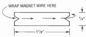
FIG. 3--THIS WIRE SPOOL allows easy winding of the torriod transformer
(see text).
Construction
Everything except the relay and fuse are mounted on a PC board, for which we've provided a foil pattern-you can also buy a pre-made board if you like (see the parts list). If you use the PC board, you'll have to drill the holes in the case cover very accurately in order to accept the switches, LED, and potentiometer directly from the circuit board. One way to deal with this problem is to drill a tiny pilot hole on the circuit board in the center of each component location that must come through the top cover.
Then place the unpopulated circuit board directly onto the top cover and transfer the holes. This problem should be dealt with be fore installing the components on the board. Figure 2 shows the parts-placement diagram.
The torriod transformer was constructed from a 0.5-inch powdered-iron torriod. A wire spool was made from a scrap of PC-board material, about 1 1/4-inches long by 1/4-inch wide with V-shaped notches cut at both ends (see Fig. 3), and 30-gauge magnet wire was wound on the spool between the two notches.
The spool was then pushed in and around the core of the torriod (like a sewing needle) forming a 100-turn coil (T1's secondary) all the way around the entire torriod core (you unspool the wire as you make the turns). The ends of the 30-gauge magnet wire were stripped and carefully soldered to 24-gauge wires. Five minute epoxy was then brushed over the secondary coil. After the glue dried, the two splices were glued to the edge of the torriod with another spot of epoxy to re duce the stress on the 30-gauge wires.
The primary coil was wound over the secondary using two turns of 16-gauge wire with insulation heavy enough for about 12 amps. Heavy linecord can be used for the primary if you like.
The torriod was placed over the square notch on the end of the PC board (as shown in Fig. 2), and attached to the board with a plastic strip placed over the torriod and fastened with two screws.
One of the 16-gauge wires was connected in series with the 12-amp fuse; the other end of the fuse was connected to an alligator clip. The other 16-gauge wire was connected to one end of RY1's normally closed contact.
The remaining relay contact was connected to another alligator clip. Note that the relay used in the prototype is a double-pole unit with the contacts wired in parallel to handle higher current.
Figure 4 shows the prototype. A later version of the electronic fuse replaced the alligator clips with a chassis-mounted female power receptacle. The device under test is plugged into the outlet on the electronic fuse and a 12-amp fuse is placed in the fuse holder of the device being tested.
The electronic fuse, set at the fuse value of the device being tested, will then fully protect the faulty circuit until you have located the problem. Then simply replace the original value fuse in the circuit you just repaired.
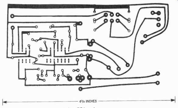
---- FOIL PATTERN for the electronic fuse PC board.
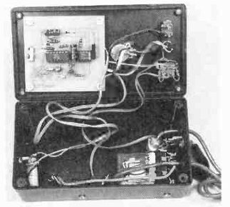
FIG. 4--EVERYTHING EXCEPT the relay and fuse are mounted on the PC board.
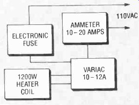
FIG. 5--CALIBRATION IS PERFORMED using a 1200-watt heating element coil
connected to the output of a variac (see text).
Operation
Operation of the electronic fuse is quite simple. The alligator clips connect to the fuse holder of the device under test, essentially substituting the electronic fuse for the fuse that was in the original circuit. First choose the high- or low-sensitivity position of S1i; the low range covers 'ho to 6 amps and the high range covers 1 to 10 amps with overlap between the two ranges. Next adjust R7 for the current setting that best rep resents the desired fuse value. Turn on the power switch S2, and reset the electronic fuse by pressing S3. Now turn on the device being tested; if LED-1 lights, the "fuse is blown" and you must re set the circuit by pressing S3. Continue to troubleshoot until the repair is completed.
Calibration of the Electronic Fuse was performed by using a 1200-watt heating element coil, but an electric fry pan or toaster could be used instead. The thermostat in a fry pan must be turned up to maximum or disabled. The heater is connected to the output of a variac and the input of the variac is connected in series with an ammeter and the electronic fuse (see Fig. 5). The variac output is slowly stepped up in small increments. A calibration sheet is placed under R4's adjust knob.
Calibration must be done for both the high and low ranges. Begin by selecting the low range, and turn R4 clockwise to about midway. Next turn on the variac and adjust for about 1 amp, then rotate R4 to the trip point. Place a pencil mark on the calibration sheet, back down the variac, and reset S3. Bring up the variac to the point you just marked for one amp, and watch the meter to en sure that you are drawing one amp as the breaker "trips." Now proceed with the next value, ad just R4 past midway, set the vari ac for two amps, and rotate R4 down to the trip point. Repeat the procedure for each fuse value in the low and high ranges.