Source: Radio Electronics--Electronic Experimenter's Handbook (1993)
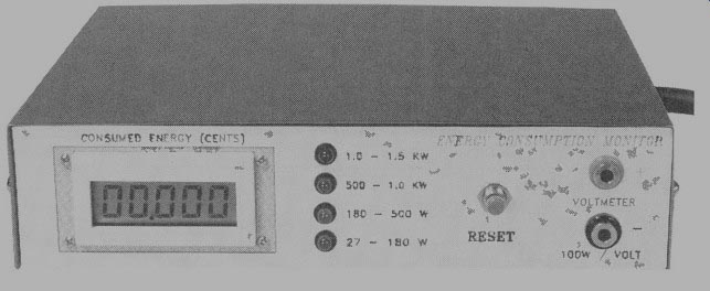
Build this energy consumption monitor and find out how much it costs to
run your household appliances.
By PAUL BRULE
IF YOU'RE CONCERNED WITH ENERGY cost and conservation, as most people are, you'll be interested in our energy consumption monitor (ECM). Without the ECM, it's difficult for the average person to determine how much an individual home appliance costs to run. That's especially true for appliances with variable duty cycles such as a refrigerator which will have its compressor and fan motors, lights and other loads on at different times.
Our energy consumption monitor can display the accumulated cost in cents for the connected home appliance load. What did you spend to operate your toaster yesterday? What about your TV or air conditioner? Is the cost of energizing that spare freezer unit worth the few pennies saved when you bought your meat on sale? The ECM will help you to answer those questions quickly.
The ECM can also be used as a power meter by connecting a DMM to the voltage output of the monitor. Using the DC scale of your meter, each volt represents 100 watts. For example, a reading of 0.56 volts would translate to 56 watts.
To give you an idea of what the average residential Long Island, NY consumer pays monthly for operating various appliances, refer to Table 1. The monthly cost was based on a rate of 13 cents per kilowatt-hour (kWh). The average Long Island resident uses about 600 kWh's per month, which translates into a monthly electric bill of $91.81.
The current electric rates for the Long Island, NY area are among the highest in the U.S. and vary depending on the sea son and the total amount of kWh's used. The summer rates are 12.871 for 0-250 kWh's used and 14.1c for 250-350 kWh's.
The winter rates are 12.87c for 0-250 kWh's and 12.33c for 250-350 kWh's. Of course electric rates will vary, depending on the size of your family, the region of the country in which you live, and the utility company who ser vices you. The information provided is only a rough basis to compare your own power consumption to that of the average Long Islander. Let's see how this useful device works.
About the circuit
The ECM circuit consists of four sections, as shown in the block diagram of Fig. 1. A power converter generates a voltage that is proportional to the true or real power consumed by the load.
That voltage feeds both a bar-graph and a voltage-to-pulse converter. The bargraph gives an approximate indication of the amount of power used, and the voltage-to-pulse converter produces a pulse whose frequency is proportional to the power. The pulse triggers the counter module which displays the cost of powering the monitored load.
The power converter In order to determine the actual power consumed by an appliance, we must find the phase angle between the voltage and current in the overall circuit. We know that
P=V x l cos θ
where cos θ is known as the power factor. Since the voltage of the monitored load is fairly constant at about 117 volts, we can say that the power is proportional to I x cos°. lb obtain the phase angle, both the voltage and current must be monitored.
Transformer T1 supplies the voltage, while the current-proportional voltage is obtained by stepping up (by a factor of 20) the voltage drop across shunt resistors R1-a-d via T2.
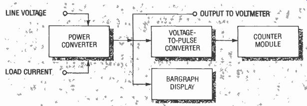
FIG. 1--THE BLOCK DIAGRAM of the energy consumption monitor.
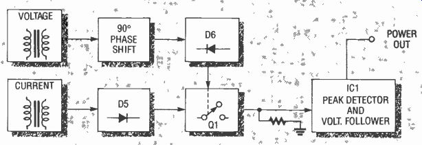
FIG. 2--THE BLOCK DIAGRAM OF THE POWER CONVERTER section of the ECM.
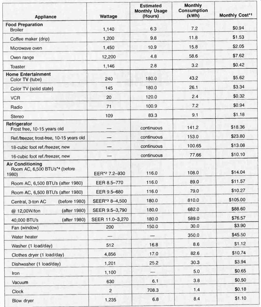
TABLE 1--AVERAGE WATTAGE, USAGE AND COST OF HOUSEHOLD APPLIANCES
Notes*
1. The monthly cost is based on an average rate of 130/kWh.
2. Energy efficiency ratio.
3. Seasonal energy efficiency ratio.
4. BTU's/EER =watts.
All figures noted in this table were obtained from Long Island Lighting Company's (LILCO) Energy Conservation Department.
The ECM is capable of accurately monitoring the effective power of inductive loads. If a capacitive load is connected to the ECM, only the apparent power, not the effective power, will be monitored, causing some degree of inaccuracy. That shouldn't pose much of a problem because just about all reactive household loads are inductive. However, some appliances such as refrigerators, freezers, and air conditioners use capacitor-start inductive motors, which are characterized by a high starting torque. Those types of motors will present a capacitive loading effect on the power line, but only during start-up, which is a very short time interval compared to the continuous operation of such appliances.
Figure 2 shows a block diagram of the power converter circuit. The voltage from the potential transformer T1 (Fig. 3-a) is delayed by 90° (Fig. 3-b), con trolling transistor switch Q1 (Fig. 3-c), which turns on during the negative cycle of the wave. Now, let's consider how three types of loads are monitored: purely resistive, equally resistive and inductive, and purely inductive.
In a purely resistive AC circuit, the current is in phase with the voltage, therefore the half-wave rectified signal from the current transformer will look like that of Fig. 3-d. Since the switch (Q1) is on until the first 90° of the wave, the peak of that wave (Fig. 3-g) will be passed on to the peak detector consisting of IC1. We can now say that Vo=V of the current transformer.
In a circuit consisting of equal resistance and inductive reactance, the current will lag the voltage by 45°. That signal, when half-wave rectified (Fig. 3-e) and gated by Q1 will look like that of Fig. 3-h. As you can see, the switch allows only the first 45° of the wave to be sampled by the peak detector, therefore
VOUT = VPK sin(90-theta).
...since...
sin (90-theta) = cos theta,
...then ...
V_OUT = V)PK COS theta.
An ideal inductor does not dissipate any power, and its AC current will lag the applied voltage by 90°. As a result, once the half-wave rectified current wave form (Fig. 3-f) of such a load is switched by Q1, the resulting output is zero, therefore V_OUT = V_PK COS theta.
(Fig. 3-i.) The schematic of the energy consumption monitor is shown in Fig. 4. Components R6-R8 and C5-C7 form a 90° phase shift network which switches Q1 on via R9 and R10 during the negative-going part of the wave. The voltage present at the secondary of the current transformer (T2) is half-wave rectified by D5. Diodes D3 and D4 limit the secondary voltage to approximately 40 volts peak to protect D6 and Q1 from excessive voltage should a high-current surge occur. When Q1 is turned on, it will couple any of the half-wave rectified signals to R11, and to the peak detector consisting of IC1-a, D7, C9, and R12. The wiper of R11 is set to calibrate the peak detector out put so that it produces 1 volt for every 100 watts consumed by the load. Finally, that voltage is buffered via the voltage follower ICI-b to feed an external voltmeter, the bargraph meter, and the voltage-to-pulse converter.
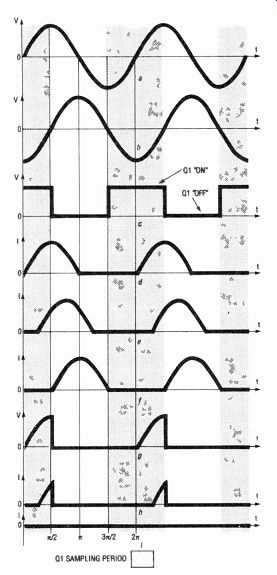
FIG.
3--POWER CONVERTER waveforms: sinusoidal waveform from T1 (a); T1 voltage is delayed by 90° (b); Q1 turns on when the delayed voltage goes
negative (c); half-wave rectified current signal from a purely resistive
load (d); half-wave rectified current signal from a resistive and inductive
load (e); half-wave rectified cur rent signal from a purely inductive
load (t); when 01 turns on, it captures the first 90° of the current
signal of a resistive load (g); sampled current signal of a resistive
and inductive load (h); sampled current signal of a purely inductive
load (i).
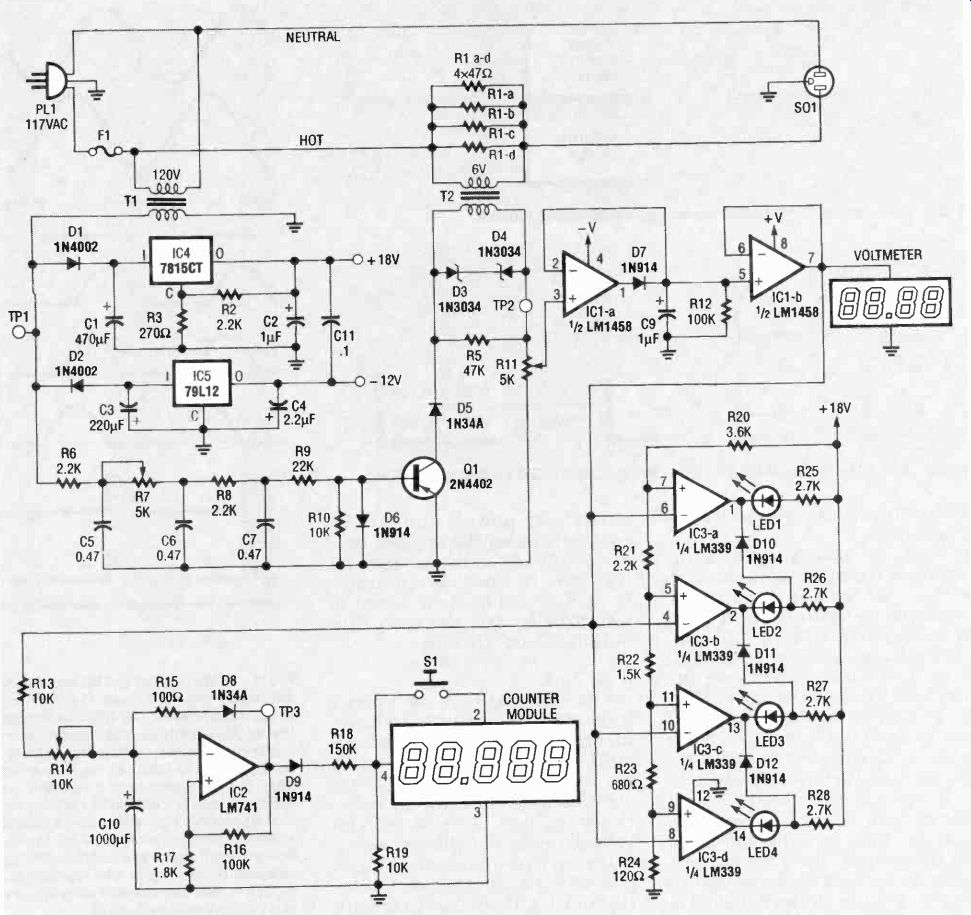
FIG. 4-THE SCHEMATIC OF THE ECM; R6-R8 and C5-C8 form the 90° phase shift
network, which switches 01 on. R11 calibrates the peak detector output so
that it produces 1 volt for every 100 watts consumed by the load. For greater
power-handling capability, R1-a-R1-d can be replaced by three 0.33-ohm,
10-watt resistors.
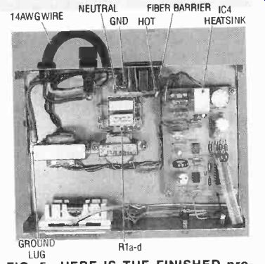
FIG. 5--HERE IS THE FINISHED prototype. It's a good idea to use standoffs
to mount the transformers so that R1-a-d's connections are adequately
spaced from the case. The author also used a fiber barrier between the
PC board and the AC socket for added protection.
The voltage-to-pulse converter is basically a voltage controlled oscillator (VCO). The power voltage (from IC1-b) charges C10 via R13 and R14 until the capacitor voltage attains the trigger voltage of the Schmitt trigger, consisting of IC2, R16, and R17. Once triggered, the negative voltage swing from the output of IC2 quickly reverses the capacitor charge via R15 and D8, and is ready to re peat the cycle again. The higher the voltage feeding the RC timing network, the higher the pulse re petition, or frequency, will be.
That pulse is used to increment the counter module through voltage-divider resistors R18 and R19. Diode D9 assures that the counter sees a pulse of the proper polarity. A nice feature of the display counter is that it is powered by a single AA battery mounted on the back. That makes sure the count is retained if the ECM is unplugged, or in the event of a power failure.
At the heart of the bargraph is 1C3, a quad comparator. The power voltage drives all of the comparator's inverting inputs while each of the non-inverting inputs are tied to different voltage references derived by the voltage divider network of R20 to R24. As the voltage signal in creases above the reference voltage level, the open collector output of that particular comparator goes low, switching its corresponding LED on. Diodes D14, D15, and D16 ensure that the previously lit LED is turned off as the power increases, thus allowing no more than one LED to remain on at a time.
The power-supply section is fairly straightforward. The trans former's (T1) voltage is half-wave rectified, and is then filtered by C1. The voltage divider R2 and R3 is used to boost the output voltage of regulator 1C4 to approximately 18 volts. 1C4 could easily be replaced with a 7818 voltage regulator, thereby eliminating the need for R2 and R3 (a shorting jumper would have to replace R3). Except for the voltage-divider resistors, the negative supply is basically a mirror image of its positive counterpart.
Construction
Figure 5 shows the authors completed prototype. Transformers T1 and T2, S01, F1, LED1-4, counter display, S1, J1 and J2 are mounted on the en closure, while the remaining secondary circuitry is installed on a single-sided PC board. The foil pattern is provided if you would like to make your own, or you can obtain an etched and drilled board from the source mentioned in the parts list. Mount and solder all components ac cording to the parts placement diagram shown in Fig. 6, observing correct polarity. The 7815 regulator should be fitted with a heat sink. You can do that by drilling a 1/2" x 1-1/2" x'/16" piece of aluminum and mounting it to the TO-220 case.
The ECM should be enclosed in a suitable metal case as hazardous line voltage is present. It is important to use no. 14 AWG or heavier gauge wire for all primary wiring. Make sure the neutral side of the plug corresponds to that of the socket. The photograph in Fig. 5 shows where the hot (power supply black lead) and neutral (white lead) conductors are connected.
Grounding should be made by terminating the green grounding conductor of the power-supply cord and socket ground lead to a closed-loop connecter. Mount the connector through the trans former mounting screw and se cure to the chassis ground through a star washer to bite through the painted or plated metal case. You can also sand the paint away to make a good con tact. Resistors R1-a-R1-d should be adequately ventilated by using a louvered enclosure top. Those resistors could get quite hot if constant heavy loads over 1000 watts are monitored.
Now it's time to mark a decimal point on the counter display.
Using a fine-tip black felt pen, mark the decimal point on the display between the third and fourth digit so that, when the monitor is properly calibrated, each count represents '/moo of a cent.
When wiring T2, remember to wire the 6-volt winding across the shunt resistors R1-a-R1-d so that you're using it in a step-up mode.
Locating a 3.6K resistor for R20 may be rather difficult since that is a non-standard value. The author happened to have a few of them in his parts collection, but you may consider wiring a 3.9K and a 47K resistor in parallel to obtain that value.
=============
PARTS LIST
All resistors are 1/4-watt, 5%, un less otherwise indicated.
R1-a-d-0.39 ohms, 5 watts R2, R6, R8, R21-2200 ohms R3-270 ohms R4-not used R5-47,000 ohms R7, R11-5000 ohms, trimmer potentiometer R9-22,000 ohms R10, R13, R19-10,000 ohms R12, R16-100,000 ohms R14-10,000 ohms, trimmer potentiometer R15-100 ohms R17-1800 ohms R18-150,000 ohms R20-3600 ohms (see text) R22-1500 ohms R23-680 ohms R24-120 ohms R25-R28-2700 ohms
Capacitors
C1-470 µF., 35 volts, radial electrolytic C2, C9-1 35 volts, tantalum C3-220 µF, 63 volts, radial electrolytic C4-2.2 µF, 35 volts, radial electrolytic C5, C6, C7-0.47 µF, 100 volts, polyester C8-not used C10-1000 µF, 16 volts, radial electrolytic C11-0.1 uF, 50 volts, ceramic
Semiconductors
D1, D2-1N4002 diode D3, D4-1N475A, 30 volts, Zener diode D5, D8-1N34A germanium diode D6-D12-1N914 diode Q1-2N4402 PNP transistor IC1-LM1458 dual op-amp IC2-LM741 op-amp IC3-LM339 quad comparator IC4-LM7815 or LM7818 voltage regulator (see text) IC5-LM79L12 12-volt negative voltage regulator LED1-red LED LED2-LED4-green LED
Other components
F1-15-amp fuse S01-chassis-mount, grounded AC socket T1-18 volts (or 24 volts), 200 mA transformer T2-6 volts, 200 mA transformer (connected as a step-up trans former) Counter module-LCD electronic counting module (Radio Shack number 277-302) S1-momentary SPST push button switch
Miscellaneous: 2 chassis-mount banana sockets, fuse socket, strain relief, PC board, hardware, wire, metal enclosure (Radio Shack 270-272A).
NOTE: The following items are available from Paul Brule, 12L 67 Harbourview Rd., Port Colborne, Ontario, Canada L3K 5V4. An etched and drilled PC board, $15.95; a kit consisting of all resistors, capacitors, semiconductors and PC board for $59.95; a lettered faceplate and template which fits a Radio Shack 270-272A case, $7.95.
Please include $2.50 for ship ping and handling. All prices are in US funds.
=============
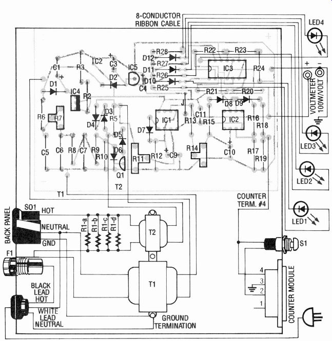
FIG. 6--PARTS PLACEMENT DIAGRAM AND WIRING connections. Use 14 AWG wire
for all primary sure you wire the hot and neutral leads of the power
supply cord to the proper terminations on the AC socket.
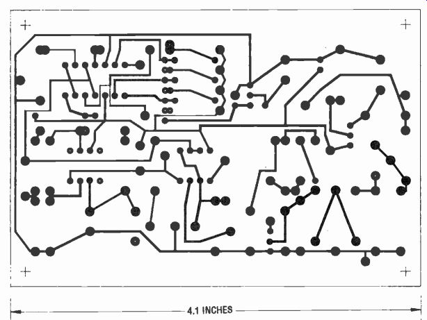
------------THIS IS THE FOIL PATTERN of the solder side of the PC board.
Calibration and testing
Before applying power to your circuit, double check your wiring. If you're using IC sockets, leave IC1, IC2, and IC3 out of the circuit. Apply power and check for +18 volts and -12 volts at the outputs of IC4 and IC5, respectively. Those voltages may be slightly lower by a fraction of a volt. If you have removed the IC's and the voltages are okay, then unplug the unit, install the IC's, re-apply power, and re-check the supply voltages.
The next step is to check the transformer phasing. In order to do that, temporarily install a jumper from ground to the cathode of D5. Now connect a 100-watt light to the load socket.
Using a voltmeter on the AC scale, make sure the voltage be tween TP1 and TP2 is lower than that measured between TP1 and ground. If it isn't, reverse the two PC-board connected T2 leads. Re check and remove the jumper.
With NO LOAD connected to the ECM, connect a jumper be tween the + 18-volt supply and TP2. Connect a DC meter to the power-voltage output and check to see that the voltage varies from 0 to approximately 16.5 volts as R11 is varied from one end to the other. As you do that, the LED's should increment at about 0.27, 1.8, 5, and 10 volts. Now, using the formula VcAL = 36/rate, where VIAL is the calibration voltage and rate is your cost in cents per kilowatt-hour (check your billing statement or power company for that rate). Adjust R11 to read that value on the volt meter. That will enable you to calibrate R14 so that you obtain one pulse per second (1 Hz) at TP3. A doubling or halfing of VcA, should approximately double or half the pulse rate. Remember, each pulse represents Vi000 of a cent.
Disconnect the jumper used in the previous procedure and connect a 100-watt light as a load.
Using an oscilloscope, monitor the waveform at TP2 and set R7 so that the sampling ends at the very peak of the incoming wave form, which should look like the waveform of Fig. 3-g.
Finally, power calibration is the last to be performed. With the 100-watt light connected adjust R11 so that a DMM, connected to the external voltmeter jacks, displays 1.00 volt DC. You may want to verify that wattage by measuring the voltages across shunt resistor RI, and the line. With those two voltage readings, the power maybe calculated using the formula P(watts) = VSHUNT X VLINE/RSHUNT, where RSHUNT is the shunt resistance (four 0.39-ohm resistors in parallel = 0.0975 ohms). VSHUNT is the voltage drop across R1 and VLINE is the AC line voltage.
That completes the assembly and calibration of the ECM.
There is one point that should be mentioned here. The voltage to pulse converter will not start until there is a load of approximately 30 watts, meaning that the counter will not increment unless the load is heavier than that value.
For those of you wondering if investing in an energy consumption monitor is worthwhile, consider this: You'll be able to determine how much it costs to run a particular appliance for a certain length of time. So it's easy enough to figure out if it's actually cheaper to run the micro wave oven for five minutes or the conventional oven for ten minutes, and so on. Using the energy consumption monitor, you'll also be able to determine if buying extra meat at really good sale prices actually saves you money in the long run. The greatest advantage of the energy consumption is keeping one step ahead of your power company.