AMAZON multi-meters discounts AMAZON oscilloscope discounts
34. Gas-filled Phototubes
The term phototube as used in this guide refers to a light-sensitive device which consists of two electrodes in a glass envelope.
One electrode, the cathode, emits electrons when its sensitive surface is acted upon by radiant energy of the wavelength or wavelengths for which it is designed. The second electrode termed the anode is operated at a positive potential with respect to the cathode and sets up an electro-static field which causes the emitted electrons to move toward it. The number of electrons involved in the transfer is determined by the specific sensitivity of the cathode surface to the wavelength of radiation being used and by the quantity of radiant energy reaching the surface. For a given phototube operating with a specific wavelength of radiation, the magnitude of the anode current is thus a function of the amount of energy it receives.
The envelopes of many modern phototubes (Fig. 34) are evacuated to very low pressure. When characteristic curves of anode voltage vs. anode current with constant illumination are taken, the tube does not operate under conditions of space charge at all. In this way, the phototube differs from a thermionic diode. Absence of space charge is explained by the fact that so few electrons are emitted from the cathode (even under strong radiation) that it re quires very little anode-to-cathode potential to attain the equivalent of thermionic diode temperature saturation. That is to say, a very small voltage applied between the two elements will result in the attraction of all the emitted electrons to the anode.
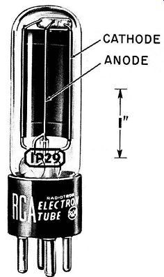
Fig. 34. Cutaway view of a 1 P29 gas phototube (photo-emissive).
The presence of a small amount of some inert gas like helium or argon produces an increase in the anode current of a given photo tube without change of illumination. This increases the sensitivity of the tube as compared with corresponding vacuum types. The mechanism of this improvement is quite similar to those previously discussed relative to the passage of small currents through gases:
1. The flow of primary or photo-electrons from the cathode produces ionization of the gas;
2. The collision electrons now become available as charge carriers and add to the photo-electrons to increase the total number in the tube;
3. Positive ions reaching the cathode may produce secondary electrons which further swell the total number of electrons moving between the cathode and the plate. The total current flowing in a gas-filled phototube may be several times larger than that of the corresponding vacuum-type operated with the same illumination and anode voltage.
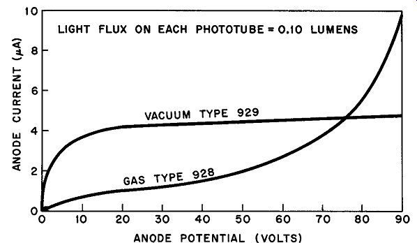
Fig. 35. Comparison of characteristic curve of gas phototube with equivalent
curve of vacuum type.
We can draw many interesting conclusions from the curves in Fig. 35. The flattening of the vacuum phototube characteristic be yond about 40 volts of applied potential shows that the equivalent of temperature saturation in a thermionic diode has been reached at this point and that increasing the anode potential has little effect upon the anode current. At low anode voltages the available current from the vacuum type is greater, but the superiority of the gas tube in this connection becomes evident as the anode potential is raised above approximately 75 volts. At 90 volts, the gas tube current is about twice as great as that of the vacuum tube. The curved incremental of the gas type between 60 and 90 volts of anode potential indicates increased ionization and accounts for the rapid rise of anode current.
Phototubes of the 929 type (868, 918, 923, etc.) are rated at a maximum anode supply voltage of 90 volts. Since the glow discharge in the gas tube must at all costs remain non-self-sustaining, any attempt to increase the voltage above the recommended value may result in a self-sustaining discharge which would quickly ruin the cathode by sputtering.
35. Cold-cathode Gas Tubes (Grid Glow Tubes)
Gas-filled cold-cathode triodes are known as trigger tubes or cold-cathode gas tubes (Fig. 36) . Sometimes these are classified as grid-glow tubes, although the third element is more properly referred to as a starter anode or control electrode rather than a grid.
The cathode may be a nickel-iron element coated with a barium and strontium mixture. The anode is usually pure nickel in the form of a wire shielded from the other electrodes by a glass cylinder; the end of the nickel wire protrudes above the end of the cylinder and is spaced from the other elements by a distance which depends upon the gas, gas pressure, and general design of the rest of the tube. The starter anode may be a surface or a wire loop placed near the cathode.
The gas used is either neon, argon, or a mixture of the two.
The spacing between the control electrode and cathode is substantially smaller than the spacing between the anode and cathode so that a discharge can occur at a lower voltage between the first two.
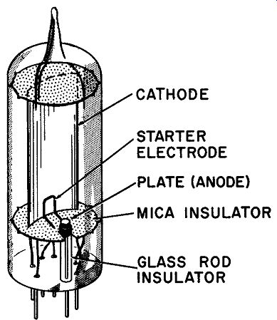
Fig. 36. Structure of a cold-cathode gas tube (grid glow tube).
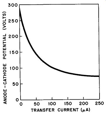
Fig. 37. How required anode voltage varies with transfer control in the 0A4-G.
At the instant of this primary discharge, ionization occurs and the discharge transfers to the main anode. In order for the transfer to occur, the anode-cathode voltage must be adjusted to a specific value, the voltage required being determined by the cathode-starter anode current or transfer current. The curve shown in Fig. 37 illustrates how the required anode voltage varies with transfer current. It should be noted that the required anode voltage at zero transfer current is the same as the potential required to start the discharge if the starter anode is not in the circuit. In practice, of course, the anode voltage is therefore always lower than this self-initiating level -- less than 250 volts in the case of the 0A4-G. The necessary anode voltage falls more and more rapidly as the transfer current is raised, indicating increased ionization. Figure 38 gives a basic circuit for using the cold-cathode tube as a relay. The voltage Ea is greater than the self-sustaining voltage of the tube but less than the break down voltage; the voltage E, is applied to the starter anode through the input coupling device and is slightly less than the potential required to initiate the action. A positive pulse applied to the upper input terminal adds to E, bringing the voltage above the breakdown point for the starter circuit. The starter-cathode discharge then initiates the main discharge and the load is energized.
It should be noted that this is a self-latching action which can be opened only by reducing the anode potential so that it falls below the voltage required to maintain the discharge. In this connection we might mention that cold-cathode gas (grin-glow) tubes can be classified in the same general group as small thyratrons such as an 884 or a 2050 on the basis of current handling ability. These tubes are capable of passing approximately 100 milliamperes on continuous service and are suitable for use as small controlled rectifiers, voltage regulators, relaxation oscillators, relays or switching devices.
36. Mercury Pool Rectifier
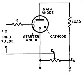
Fig. 38. The cold-cathode gas tube used as a relay.
Although large thyratrons can handle up to 200 kilowatts of rectified power, they are essentially high-voltage-low-current devices because the average current does not exceed 12 amperes and the large amount of power mentioned can be obtained only with voltages around 15,000 volts.
From the industrial point of view -- particularly in low voltage applications (200 to 500 volts) -- the mercury-pool cathode rectifier is much more suitable. The earliest pool rectifiers were constructed in tube form as shown in Fig. 39. A cold mercury pool does not emit electrons, but a plentiful supply of electrons can be obtained from it if a stream of the liquid that has a current passing through it can be quickly broken to start an arc. The tube in Fig. 39 is operated this way. To initiate the arc, the tube is tipped to the right so that a stream of mercury flows from the main pool into the well along the side arm. Current then flows through the stream as a result of the potential applied between the starting electrode and the pool. As the tube is returned to the upright position, the stream breaks and an arc begins between the auxiliary electrode and the pool surface. This results in the formation of a cathode spot at the surface of the pool from which enormous numbers of electrons are liberated. Situated as it is in the strong electric field of the anode, the pool supplies the electrons to the anode to initiate a self-sustained arc.
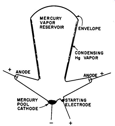
Fig. 39. An early form of mercury-pool rectifier.
Electrons enter the arc through the cathode spot which moves freely about the surface as a result of the forces exerted on it by the returning ions and the vaporizing liquid around it. Mercury ions formed in the body of the tube are either returned to the pool by electrostatic action where they pick up the necessary electrons to re-form into atoms of liquid mercury, or they are neutralized on the glass walls where they condense as a result of cooling. The condensed mercury drops down the walls and returns to the pool in this manner. Thus, cathode material is constantly being replenished; an electrode of this kind is virtually indestructible.
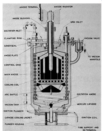
Fig. 40. Vertical cross-section of an excitron rectifier tube.
Modern multiphase mercury-pool rectifiers are manufactured in the form of cylindrical steel tanks from 1 to 2 ft. in diameter and about 4 ft. high. Each tank rectifier contains a single pool and a single anode together with its starting mechanism. (Multi-anode rectifier tanks are fast becoming obsolete and will not be discussed here.) One of the disadvantages of the older forms of mercury-pool rectifiers was that some form of manipulation was required to restore the arc each time it was lost. To make the pool rectifier just as convenient as thermionic types, a continuous supply of electrons is required whether the arc is struck or not. This is accomplished by maintaining at all times an auxiliary arc between the pool and a special excitation electrode located just above the cathode.
To start the arc, a fine stream of mercury is hosed from the pool to the excitation electrode, short-circuiting the two elements momentarily to initiate the arc. The voltage applied between the starting device and the cathode is approximately 35 volts de obtained from a separate source so that the excitation arc is maintained continuously.
The sustained excitation mercury-pool rectifier is often commercially called an "excitron." This unit also includes a grid which exercises the same type of control over the anode current as the equivalent element in the thyratron (Fig. 40). 37. The Ignitron
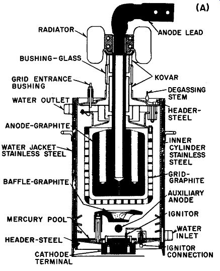
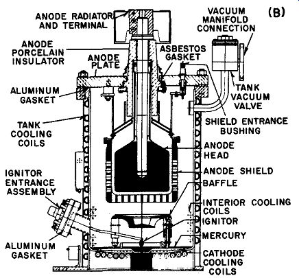
Fig. 41. Sectionol views of typical ignitrons; (A) Sealed type; (B) Pumped
type. Westinghouse.
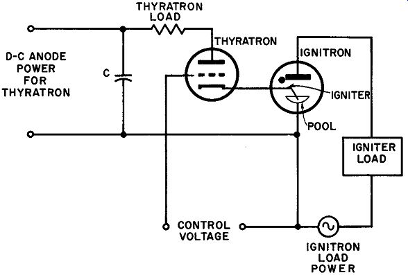
Fig. 42. How a thyratron can be used to control the firing angle of an ignitron.
The ignitron differs from the excitron in that initiation of the arc is based upon a completely different principle. Once an arc is struck in the excitron it is maintained by the excitation electrode connected across a source of separate de. In the ignitron, however, the main arc is permitted to extinguish completely on every non conducting half-cycle and is reinitiated at the beginning of the following conducting half-cycle. The energy for ignition is supplied through the action of a bar of semi-conductor refractory material such as carborundum which dips into the main mercury pool, as illustrated in Fig. 41. When a current of 5 to 20 amperes flows from the ignitor rod to the mercury, tiny arcs form between the surface of the semi-conductor and the surface of the pool, initiating the arc. Transferable from the ignitor to the main arc is almost instantaneous, hence current can flow in the main arc circuit over virtually all of the conducting half-cycle. The ignitor itself is pulsed periodically at exactly the right instant making the power consumption of the auxiliary circuit relatively small.
One of the most important features of the ignitron is its suit ability for current control via the ignitor circuit. Here again, firing angle enters the picture: the average output current of any con trolled rectifier is a function of the portion of the half-cycle over which it conducts.
One of the best ways to control the firing angle of an ignitron is to use a thyratron as an ignitor trigger. Figure 42 illustrates one of the many ways this might be done. A phase shift control circuit, such as that described earlier, determines the firing angle of the control thyratron; as this tube fires, its anode current passes through the ignitor circuit striking the main arc of the ignition. Anode potential for the thyratron is provided by the charge across C so that as soon as C is discharged by the conducting thyratron, the latter extinguishes and the grid circuit regains control. Thus, the portion of the cycle for which the ignitron conducts is determined by the firing angle of the thyratron which, in turn, may be varied by the grid control voltage. This kind of system is very economical on ignition power and extremely dependable.
Ignitrons are used for heavy duty rectification being capable of handling very large currents continuously. Another important application is control switching in welding and similar operations.
In conclusion, there is a very basic difference between the grid control action in a thyratron and ignitor-rod action in an ignitron.
The grid of the thyratron inhibits ignition while the ignitor rod of the ignitron initiates the duty cycle. In the former case, electrons are always present owing to thermionic emission and the electrostatic action of the grid prevents the electrons from reaching the anode until firing occurs; in the latter, the tube does not have free electrons which might produce ionization of the gas until the cathode spot is formed.
QUIZ
1. What controls emission in a phototube?
2. Why is there no space charge in a phototube?
3. What is the maximum rated anode voltage in a 929 tube?
4. Name five uses of the cold-cathode gas tube.
5. What device is used to make the mercury-pool rectifier equal to a thermionic emission tube?
6. Explain the basic difference between the ignitron and the excitron.
7. How do we control time of current-flow in an ignitron?
8. What is the basic difference in the action between the grid of a thyratron and the ignitor in an ignitron?
9. What is the life of the cathode in a mercury-pool tube?
10. Name some uses of the ignitron.