Volt-Ohm-Milliammeter
Later on in this book various techniques for rapid servicing of a defective radio will be discussed. One thing, however, is common to all these techniques - a method of measuring the values of resistance, voltage, and current. Individual meters, properly arranged with the correct values of multipliers or shunts, can be used to read those values. An assortment of individual meters would be a costly and clumsy method of servicing a radio receiver. The obvious answer is a combination of multipliers and shunts placed in a switching circuit with a single, basic meter movement. Those combination circuits are called multimeters, and in the case of the most commonly used type, they are called a Volt-Ohm-Milliammeter, or VOM.
The type of multimeter using vacuum tube circuits is called a Vacuum Tube Voltmeter, or VTVM. A VTVM is also capable of reading resistance by measuring a small value of voltage across the unknown resistor.
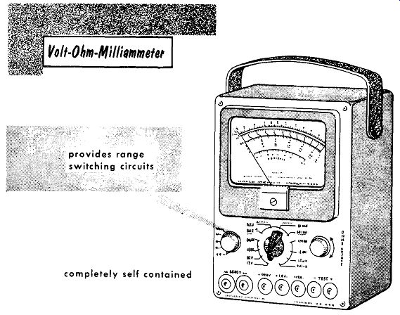
------------ completely self contained
Discussing first the VOM, we find it to be one of the basic tools of servicing. It is convenient in that it is lightweight, portable, and completely self-contained, requiring no external source of power. It can measure voltage, resistance, and current. Switching circuits are required to provide the proper ranges for individual measurements. These circuits can be simplified and shown as individual circuits.
D-C Voltmeter Circuit
To simplify the discussion of the VOM, its individual circuits have been isolated and explained as though each were a single instrument using the same basic meter movement.
The basic d-c voltmeter circuit illustrated is a straightforward arrangement of multiplier resistors in series with the meter movement. The meter movement used in all circuits is a 50-microampere D' Arsonval type with a coil resistance of 2000 ohms. In order to read high voltages of 5000 volts, a separate jack terminal is provided on the bottom right-hand side of the meter panel. With the negative or common terminal on the bottom left-hand side, wide spacing between the input jacks is available, preventing possible arc-overs.
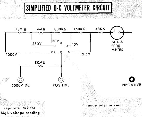
------------- separate jack for high voltage reading; range selector switch;
Courtesy of Simpson Electric Corporation
Although it is not noted on the switch positions, the meter will also read from 0 to 250 millivolts. The use of the meter to read this small a value requires extreme care. At this range it is easy to apply excessive voltage and damage the meter movement. To use the meter to read to 250 millivolts, it is set for a current reading of 100 microamperes. The 0-250 volt d-c scale is read directly in millivolts.
A-C Voltmeter Circuit
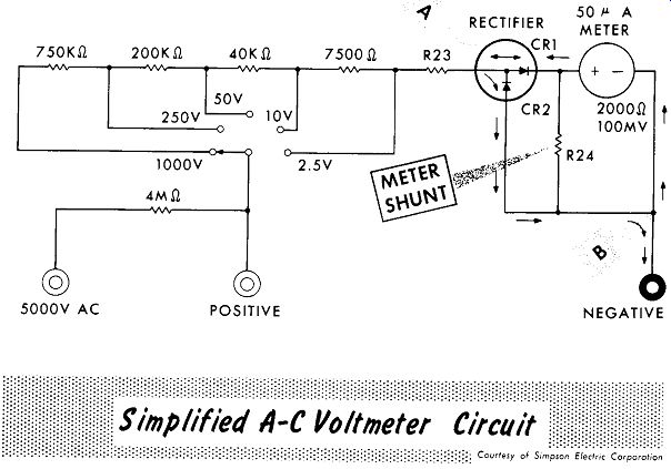
To read a-c volts a similar circuit to that of the d-c voltmeter is used with the addition of a rectifier circuit. Meter rectifier circuits are similar to other rectifier circuits previously discussed, but they have inherent problems that merit discussion. The most popular rectifier used is the copper oxide type. These consist of copper discs, each having a layer of copper oxide on one side. They are separated by lead washers and tightly clamped together. The symbol used for copper oxide rectifiers is the same as that used for crystal rectifiers -- an arrow and bar, with the bar being the cathode. Copper oxide rectifiers are long-lived, but temperatures above 160° F will quickly shorten their life. The stray capacitance of the copper oxide rectifier restricts a-c measurements to the audio range of frequencies.
This rectifier circuit is a double section, half-wave rectifier circuit. During the first alternation, assume that point A is positive, and the electron flow is from point B, through the meter, through CR1 to point A. On the second alternation, the electron flow is from point A, through the low resistance of CR2 to point B. Diode CR2 prevents the possibility of any small reverse current flowing through CR1 and the meter. This small reverse current could cause the needle to deflect backwards. In addition the current flowing through CR2 removes the peak inverse voltage that would normally be applied between points A and B on the second alternation.
------------
-------------
A-C Voltmeter Circuit ( cont’d)
The resistance of a copper oxide rectifier varies with the value of current flowing through it, causing the meter readings to be crowded together at the lower ranges. Because of the rectifier resistance, the meter needle does not deflect as far as it would if de had been applied. Reduced values of multiplier resistors are used to overcome this problem.
To overcome the crowding, or nonlinearity of the meter readings at lower values, a shunt is placed across the meter. When using a shunt with a 200 microampere movement, a typical value will be one-fourth of the meter resistance. This causes four times as much current to flow through the shunt as will flow through the meter. Full scale deflection now requires 1000 microamperes or 1 milliampere. Of this 800 microamperes flows through the shunt, 200 microamperes through the meter. Since it now takes 1 milli ampere for full-scale deflection the sensitivity of the a-c voltmeter circuit is 1000 ohms per volt.
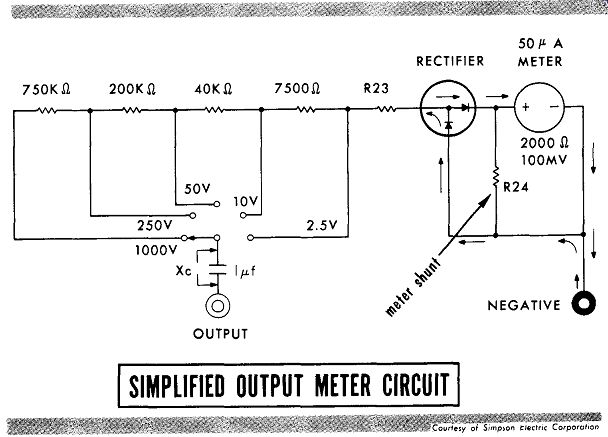
Where the a-c signal component is combined with a d-c voltage, such as at the plate of an amplifier tube, the a-c component can be isolated and read by use of a blocking capacitor. This feature is useful in reading the output of the audio circuits of a receiver during alignment. A blocking capacitor and a separate function switch position permits the use of the a-c voltmeter circuit as an output meter.
Ohmmeter Circuit
The two basic types of ohmmeter circuits are the shunt type and series type. The shunt type, excellent for use in reading low values of resistance, has a decided disadvantage in that the battery is always in use, and if left on by accident it quickly runs down. In the series type circuit, the scale becomes crowded on the left-hand side of the scale. To relieve this crowding a shunt resistor is placed across the meter. Different ohmmeter ranges can be switched in by varying the values of the shunt resistor and current limiting resistors, the zero-adjust rheostat remaining the same. Although separate scales for each range can be used, a more practical method is to calibrate the ohmmeter on the lowest scale. Multiplying the range by multiples of 10 permits using the same scale.
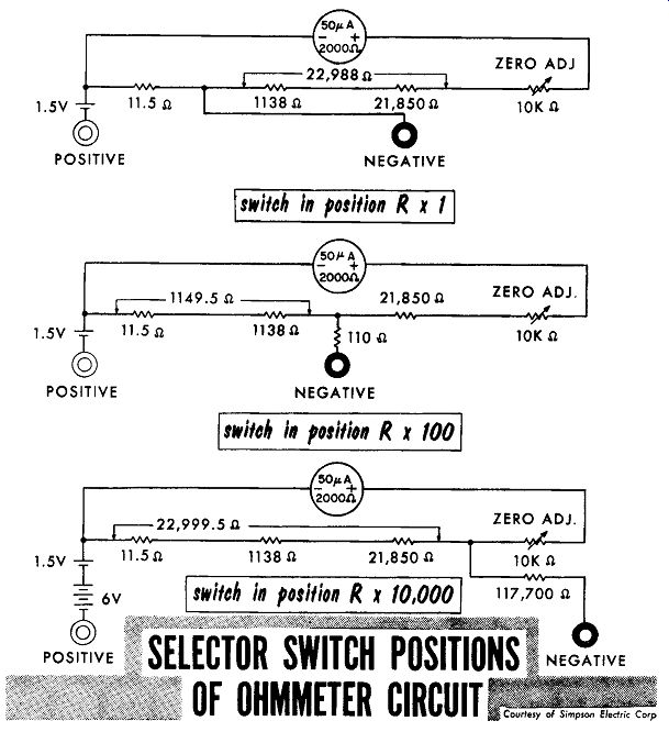
---------
Current Meter Circuit
The simplified version of the current-reading microammeter circuit is shown. With 100 microamperes applied, the current will divide, half through the five shunt resistors that total 5000 ohms, the remaining 50 microamperes through the meter resistance of 2000 ohms, and the 3000-ohm series resistor.
Thus, with 100 microamperes applied, the 50-microampere meter will read full scale.
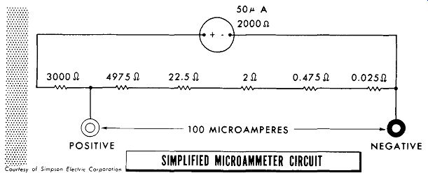
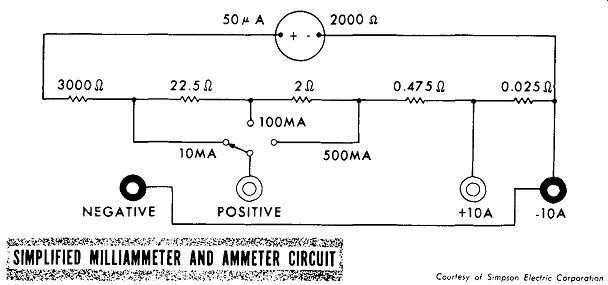
------- The combined milliammeter and ammeter circuit is shown.
With the switch in the 10-milliampere position, the 3000-ohm resistor in
series with the meter resistance of 2000 ohms (for a total of 5000 ohms)
is shunted by a total resistance of 25 ohms. In the 100-milliampere position,
the 22.5-ohm resistor is added to the 5000 ohms for a total of 5022.5 ohms.
This is shunted by a total resistance of 2.5 ohms. In the 500-milliampere
position, 24.5 ohms is added to the 5000 ohms for a total of 5024.5 ohms,
and shunted by a total resistance of 0.5 ohms. In the 10-ampere position,
24.975 ohms is added to the 5000 ohms for a total of 5,024.975 ohms, and
shunted by the 0.025-ohm resistor. In all ranges the current will divide
so as to have full scale or 50-microamperes flow through the meter when
10, 100, 500 milliamperes, or 10 amperes are applied.
--------------- Courtesy of Simpson Electric Corp.
Multimeter Circuit
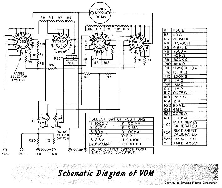
The complete schematic of the VOM is shown below. There are two selector switches - one to select the range to be measured, and the function switch which sets the circuits to read de, ac, or output. The combination of selector switches and separate test jacks permit reading six voltage ranges, five current ranges, and three ohmmeter ranges. These ranges plus the function switch permit one meter to be used to read any value of a-c or d-c voltage, of d-c current, or of resistance that would normally require twenty separate meter circuits.
-----------
All servicing techniques have one thing in common, a method of measuring values of resistance, voltage and current.
To replace a bulky assortment of individual meters, a combination of multi pliers and shunts is used in a switching circuit with a single basic meter movement. This is called a Volt-Ohm-Milliammeter, or VOM. The most popular type of meter movement is a 50-microampere D' Arsonval type movement with a coil resistance of 2000 ohms, providing a meter circuit sensitivity of 20,000 ohms per volt.
The d-c meter circuit reads a-c volts by adding a rectifier circuit.
A popular type meter rectifier is the copper oxide type. The rectifier is rugged and long-lived but sensitive to high temperatures. The stray capacity of the rectifier restricts accurate a-c voltage measurements to the range of audio frequencies.
The resistance of a copper oxide type rectifier does not vary directly with the value of current flowing through it. This nonlinearity causes crowding at the lower end of the scales.
A precaution taken to reduce crowding of the lower portion of the a-c voltage scales to place a shunt across the meter movement.
A shunt bypass, which increases the range of a meter, requires increased current for full scale deflection. The sensitivity of the voltmeter is therefore reduced.
The use of a blocking capacitor to isolate the d-c component of a varying voltage permits the use of the a-c voltmeter circuit as an output meter.
The shunt type ohmmeter circuit is excellent for reading low values of resistance, but has the disadvantage of high battery consumption.
In the series type ohmmeter circuits, the left-hand edge of the scale is crowded despite the use of shunting resistors.
All current reading ranges have shunts dividing the current so as to have 50 microamperes flow through the meter at a full scale value.
REVIEW QUESTIONS
1. Describe the metering functions available from a VOM.
2. What is the source of power that moves the meter needle of a VOM when measuring voltage or current?
3. In a comparison with a meter movement of 20,000 ohms per volt, a 1000 ohms per volt meter movement is morel less sensitive.
4. The circuit used to rectify a-c voltage for application to the d-c meter movement is a half I full wave rectifier circuit.
5. What are the two main drawbacks to the copper oxide rectifier?
6. How do we use the VOM to isolate and read the a-c signal component of a pulsating d-c voltage?
7. Describe the advantages and disadvantages of the shunt and senes type ohmmeters.
8. What is the purpose of the battery in an ohmmeter circuit?
9. With 25 microamperes flowing through the meter movement of a 50 microampere meter, what would the reading be on the 0-1 milliampere scale?
++++++++++++++++++++
Vacuum Tube Voltmeters: Basic VTVM
The standard multimeter just described is convenient and easy to use, but it has drawbacks, however, that limit its use. The main disadvantage is the possibility of its "loading" a circuit. There are many circuits of very high impedance with small values of current flowing. The standard 20,000-ohms per-volt multimeter cannot be used in these circuits due to their relatively low impedance and high current drain. Also, to increase the range of a multimeter ohmmeter circuit requires an increased battery voltage. In addition the a-c voltmeter frequency range is limited. The use of a vacuum tube voltmeter, abbreviated VTVM, overcomes these difficulties.
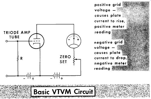
------------ negative reading
A basic VTVM using a triode amplifier tube is shown above. The meter coil winding is the plate load. By the proper choice of voltages and plate load, the tube can be set to operate on the linear portion of the dynamic transfer characteristic curve. With no signal there will be only the steady plate current flow set by the grid-bias voltage battery. The meter can be set to have a zero voltage reading in the center of the scale. Applying an unknown d-c voltage to the terminals will cause a voltage drop across resistor R. The polarity of this voltage drop will either add to or subtract from the bias voltage of the grid circuit. A positive grid voltage will cause an increase in plate current causing the meter pointer to rise. A negative grid voltage will cause a decrease in plate current causing the meter pointer to dip. Proper calibration of the meter could have it read in volts the value of plate current swing caused by the voltage under test.
The fact that the grid resistor can be of high values, such as 10 to 15 megohms, means that the grid circuit will not load the circuit under test despite being placed directly across it. The possibility of contact potential due to the stray electrons striking the grid and returning to the cathode circuit is the limiting factor in the value of grid resistor.
Basic VTVM ( cont’d)
To enable the basic VTVM circuit to be used with large or small values of test voltages, a range switching circuit is incorporated in the grid circuit. The circuit acts as a voltage divider with the switch choosing the proper voltage value applied to the grid circuit causing sufficient deflection of the meter pointer. In this circuit the test voltage is always applied to the total resistance. No matter what switch range is chosen, the VTVM offers a constant high-value impedance to the circuit under test.
The basic triode VTVM, although an improvement over the VOM, has some drawbacks. Any change in the power supply causes the zero center reading to shift, requiring constant readjustment. As the tube ages, the value of plate current varies, requiring further readjustment. The main feature of the basic VTVM is its simplicity.
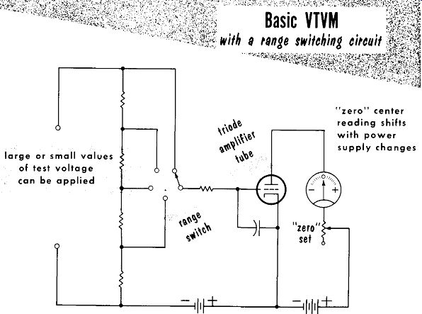
------------ large or small values of test voltage can be applied
- "zero" set
"zero" center reading shifts with power supply changes
The capacitor from grid to cathode acts as a bypass for any a-c voltage that may be combined with the d-c voltage under test. Any a-c variations in plate current will average out and cause no change in the meter reading. How ever, if the a-c component were large enough, it could change the bias voltage so that the tube would amplify on a nonlinear portion of the dynamic transfer characteristic curve.
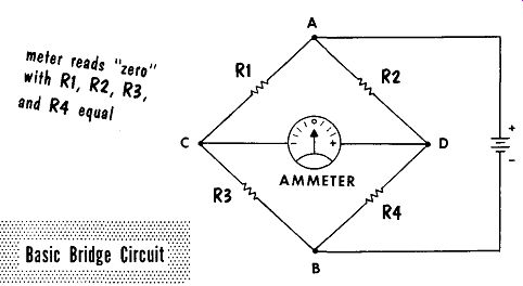
-----------
An improved VTVM circuit makes use of a bridge circuit. The basic bridge circuit is shown. With R1, RZ, R3 and R4 having equal values, the voltage drops across R1 and R3 will be identical with that across RZ and R4. Thus, points C and D will be at the same potential. With no difference in potential there is no current flow between points C and D, as indicated by a zero reading on the current meter. The bridge is thus balanced. When either pair of resistors, R1 and R3, or RZ and R4, are of unequal values, the unequal voltage drop across them will cause a difference of potential between points C and D. This difference of potential will cause current to flow; the value of current and its direction, will be indicated by the meter. The bridge is now unbalanced.
------------ variable resistance matches tube's plate resistance
to balance circuit
Replacing R3 with a vacuum tube circuit, and making R4 adjustable to match the tube's plate resistance can balance the bridge again. Applying d-c voltage to the input terminals will vary the tube's plate current thus varying its plate resistance. This unbalances the bridge as indicated by the meter reading. Proper calibration will have the meter read in proportion to the d-c voltages applied to the input terminals.
Bridge Type VTVM ( cont’d)
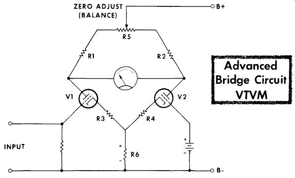
An improved version of the bridge type VTVM is shown below. The use of two tubes reduces the effects of changes in power supply voltage. When the power supply voltage increases or decreases, the plate current through V1 and V2 will increase or decrease together, keeping the bridge balanced.
Plate current for both tubes flows through R6. Making R6 a high resistance causes it to be the determining factor in current flow for both tubes, removing tube variations from determining plate current flow.

-----------
INPUT ZERO ADJUST ..-----------n B+ (BALANCE)
Advanced Bridge Circuit VTVM
Applying a positive d-c voltage to the input terminals increases the plate current of V1. The increased current flowing through R6 will cause a higher voltage drop, with the resulting change in bias causing the cathode of V2 to go in a more positive direction. Making the cathode of V2 more positive is the equivalent of making its grid more negative. This in turn reduces the plate current of V2. Looking upon the tubes as resistors in a bridge circuit, increased plate current in V1 means lower plate resistance.
Decreased plate current in V2 means higher plate resistance. The result is to have an unbalanced bridge, in the same direction, caused by both tubes, resulting in a larger flow of current through the meter. This push-pull action increases the sensitivity and permits reading small values of voltage. By setting the "zero" on the left-hand edge of the meter scale, a more sensitive meter movement may be used - typical being 1 milliampere or 200 microamperes full scale. When a negative voltage is applied, the meter pointer will move backwards; to overcome this a switch can be placed at the meter leads reversing the polarity of the meter. To balance the bridge with no input applied, RS is adjusted to have the meter read "zero", or balanced.
Differential Amplifier VTVM
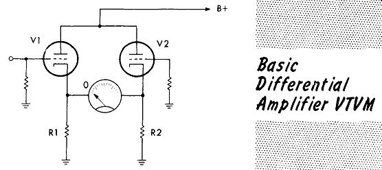
Another type VTVM uses a differential amplifier circuit. The circuit operates in this manner: applying a negative signal to the grid of V1 lowers its plate current. The plate current of V2 remains the same. The reduced plate current through V1 causes a lower voltage drop across cathode resistor R1. This places the cathode of VI at a lower potential than that of V2.
Current will flow from the cathode of V1 to the cathode of V2, deflecting the meter. The circuit is designed so that current flow will be of small value - a 0-1 ma meter movement being used for full-scale deflection .
Basic Differential Amplifier
-------
To limit the meter current to 1 ma, a variable resistor labeled "Meter Calibrate," is placed in series with the meter. To balance the circuit with no input applied, a potentiometer is placed so as to add more or less resistance in series with each cathode resistor.
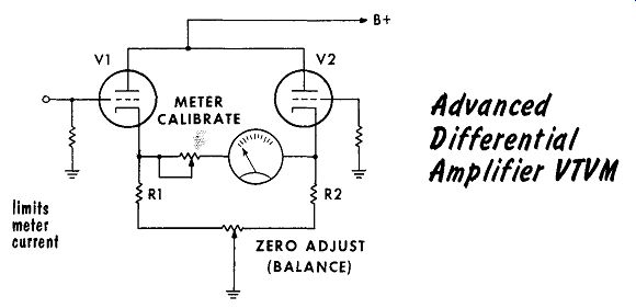
------------- limits meter current
ZERO ADJUST (BALANCE) Advanced Differential Amplifier
VTVM As A D-C Voltmeter
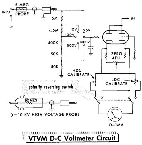
A typical, commercial, differential amplifier-type VTVM used to read d-c voltages is shown in the figure. Note that the voltage divider string of resistors totaling 10 megohms, plus the five-megohm resistor in the probe, is always parallel to the input circuit under test. Thus, the meter presents a constant impedance of 15 megohms no matter what voltage range the switch is set to read. Placing the 5-megohm resistor in the problem isolates the test signal from the meter. Shielding the probe lead keeps it from picking up induced voltages from outside circuits.
To reverse the polarity of the meter, a polarity reversing switch is placed in the cathode circuits of the differential amplifier. This permits use of a single probe -- there is no necessity of reversing test leads to match polarities. Placed in series with each side of the switch is a calibration control used to adjust the circuit against a known potential, usually a 1.5-volt cell.
----------
A special probe is available to read high voltage such as are found in transmitter power supplies. The probe is constructed with flanges for a very high leakage path to prevent shock. Using a 90-megohm resistance in the probe provides a range of 0-10,000 volts, which is read on the 0-1000 volt scale.
VTVM As An A-C Voltmeter
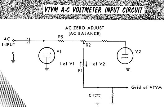
To read ac with the bridge or differential-type, amplifier VTVM circuit, the a-c voltage under test is rectified then fed to the d-c voltmeter portion of the VTVM. The use of a single diode tube to rectify the signal brings about a problem. With no applied input, the few electrons breaking away from the space charge about the cathode will go on to the plate and develop an IR drop across the rectifier load resistor; this is contact potential. The value of this contact potential may be as high as one volt. To overcome this another diode is connected as shown. With no applied signal, the polarity of the contact potential of diode V1 is developed across R1 as shown by its arrow. The contact potential of diode V2 flows through R1 in the opposite direction. Adjusting R2 to the proper value, the contact potential of diode V2 can be made equal and opposite that of diode V1.
As a result of these bucking currents, no voltage is passed on to the VTVM circuit when no a-c input is applied. Control R2 is known as "a-c balance" or "a-c zero adjust".
---------
With diodes V1 and V2 connected as shown, the negative alternations of the input signal will be removed. The positive alternations are passed on and filtered by the resistance of R1, R2, and R3, and capacitor C1. The stray capacity presented by the circuit is such that a-c voltage readings are a~ curate only with the audio-frequency range. For use above audio frequencies, a special probe is available. The special probe uses crystal diode rectifiers and extends the frequency range to as high as 100 mhz.
When the special rectifier probe is used, it is plugged directly into the d-c volts input jack.
VTVM As An Ohmmeter
To use either the bridge or differential amplifier VTVM as an ohmmeter, a battery and a resistor of known value are placed across the input terminals. With the input terminals shorted, the negative battery terminal is placed at the other end of the known value resistor, placing the full battery voltage across the resistor. At the same time, with the input terminals shorted, the VTVM de-voltage-measuring circuits are adjusted to read "zero" input.
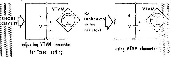
------------ adjusting VTVM ohmmeter for "zero" setting, using
VTVM ohmmeter
Placing an unknown value resistor across the input terminals causes the battery voltage to divide between the unknown value resistor and the known value resistor. The VTVM de-voltage-measuring circuits will measure the voltage drop across the unknown value resistor. The value of battery voltage across the unknown value resistor is determined by its resistance as compared to that of the known value resistor. The voltage across the unknown value resistor may be shown in ohms if the dial scale of the VTVM is calibrated in ohms.
Assume a larger value of unknown resistance is placed across the input terminals. This will result in an increased voltage drop across the unknown value resistor, and a reduced voltage drop across the known value resistor.
The VTVM will indicate this by a higher reading on the scale. As a result we find the ohmmeter scales of a VTVM are read from left to right.

-----------23 adding ranges to the ohmmeter
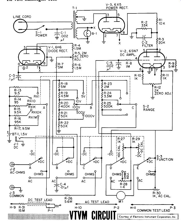
VTVM Circuit Illustrated below is the complete schematic diagram of a VTVM. The function switch also acts as a polarity reversing switch, allowing a common ground lead and a single test lead. The test lead used to measure d-c voltages contains a 15-megohm isolation resistor in the probe, and uses a shielded lead. The voltage used for the ohmmeter section is a standard 1.5-volt flashlight cell.
---------
The basic VTVM uses a triode amplifier in which the plate load is the coil of the meter movement. With the tube operating on the linear portion of its characteristic curve, application of a d-c voltage to the grid will cause a corresponding change in plate current flow through the meter coil.
The high input impedance of the grid circuit, as high as 10 to 15 megohms, means that the VTVM will not load the circuit under test.
To enable the VTVM to be used to read large or small values of voltage, a range switching circuit is incorporated in the grid circuit.
The basic triode VTVM disadvantages include tube ageing, and power supply fluctuations, both causing constant circuit readjustments.
The differential amplifier type VTVM uses two tubes with a meter connected between the cathodes of each. Any change in the cathode voltage of one tube in respect to the cathode voltage of the other will create a difference in potential indicated by the meter movement.
In most commercial VTVM's, a series resistor is placed in the d-c voltage probe to isolate the circuit under test from the meter circuit.
In reading a-c voltages with a VTVM, a single rectifier diode develops an undesired contact potential. To overcome this a second diode is connected in opposite polarity to have its contact potential buck out that of the first diode.
To use a VTVM as an ohmmeter, a battery and known-value resistor are placed across the d-c terminals. Placing an unknown value resistor across the known-value resistor and battery causes a division of the battery voltage. The voltage across the unknown resistor is read by calibrating the voltage scale in ohms.
REVIEW QUESTIONS
1. What are the disadvantages of a VOM as compared to a VTVM?
2. What is the limiting factor of the grid circuit resistor in a basic triode type VTVM?
3. In the range switching circuit of the basic VTVM, does the impedance offered to the circuit under test vary as the range switch is varied?
4. What is the main feature of the basic VTVM?
5. Describe the push-pull action of the two tubes used in a bridge type VTVM.
6. Why does the d-c voltage probe of a commercial VTVM use shielded wire?
7. Describe the special physical construction of the high voltage probe and the reason for this special construction.
8. Describe how two diodes are used to buck out contact potential in the a-c measuring circuit of a VTVM.
9. Describe how to use the crystal rectifier probe for high frequency a-c signal measurements.
10. Describe why you short the ohmmeter terminals of a VTVM to zero the meter scale.
++++++++++++++++++++++++++++++++
R-F Signal Generator
A signal generator is essentially a substitute radio station. It can be used to generate radio frequencies in the broadcast band and higher frequency bands to provide test signals for a radio receiver. In addition, it will provide the frequencies needed for correct alignment of i-f circuits, and the audio frequencies required for testing of audio circuits.
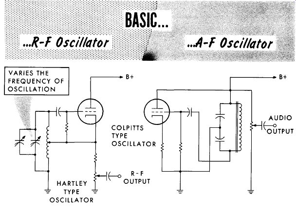
The basic requirement of an r-f signal generator is a variable frequency oscillator capable of producing the desired frequencies. These frequencies may vary from a value of 150 khz to 34 mhz. For higher frequencies harmonics are used, with the third harmonic supplying a signal as high as 102 mhz.
An r-f signal by itself is insufficient. To be a substitute radio station, the r-f signal must also be available in a modulated form. An additional part of a signal generator is the audio oscillator providing a low frequency audio signal of 400 or 1000 cycles. This audio signal is used separately, or to modulate the r-f signal.
-----------
The signal levels in the tuned circuits ahead of the detector vary from microvolts in the antenna circuit to millivolts in the output i-f amplifier circuit. The output signal level required of a signal generator is small, the average value at the output jack is 0.1 volt. This value is equivalent to 100 millivolts or 100,000 microvolts. When applying the output of a signal generator to a receiver, keep in mind that only a small value is required as a substitute signal.
R-F Signal Generator ( cont’d)
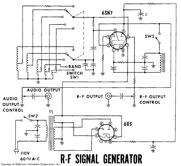
The schematic diagram of a commercial, r-f signal generator is illustrated in the figure. Switch SW1 is used to change the coils, enabling the r-f oscillator to cover a frequency range of 150 khz to 34 mhz. With the harmonic output frequencies, the generator provides frequencies usable to 102 mhz. Switch SW3 is used to switch the audio oscillator tank circuit in or out, causing the audio oscillator to be on or off. With the audio oscillator off, the output at the r-f output jack is a continuous wave (CW) signal. With the audio oscillator switched on, the 400-cycle output of the audio oscillator is available as a separate signal at the audio output jack.
Capacitor C is common to both plate circuits; it offers a low reactance to the r-f frequencies, bypassing them. At the audio frequencies the reactance of C is high, causing the plate current to vary at an audio rate. With the plates of both oscillators being tied together, the common plate current varying at an audio rate will modulate the r-f signal. With the audio oscillator switched on, the signal at the r-f output jack will be modulated by the audio frequency.
---------- R-F SIGNAL GENERATOR, Courtesy of Electronic Instrument Corp,
Inc,
Tube Testers
The need for testing tubes is obvious; faulty tubes comprise as high as 70% of the reasons for receiver defects. Testing a tube in a tester is no substitute for testing the tube in the actual circuit designed for it. Replacing the tube to be tested by a good tube of the same type is a quick and effective method of determining whether the tube or circuit is at fault.
With the multitude of different types of tubes, it would be difficult to keep replacements for all. This, plus the fact that service shops require testers to please their customers, places the tube tester in an important category.
The two most popular circuits used in tube testers are the simpler emission test and the more complex dynamic mutual conductance test. In addition, both types of testers will combine their tube test with a test for short circuits between tube elements.
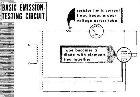
---------------- resistor limits current flow, keeps proper voltage
across tube; tube becomes a diode with elements tied together.
A tube in which the cathode emission has fallen off will cause reduced plate-current flow, reducing the output of the tube. To test a tube's emission, all elements aside from the cathode are tied together, and a voltage is then applied between the cathode and the other elements. The resulting value of plate current will determine whether or not there is sufficient cathode emission. The basic emission-testing circuit is shown above. With all of the tube's elements, other than the cathode, tied together, the tube becomes a diode. Applying ac to the tube will cause it to act as a half-wave rectifier. The measured amount of current that will flow during the alter nation, applying a positive voltage to the plate, will be an indication of the tube's emission. A resistor is placed in series with the tube to limit the current flow and keep the proper voltages across the tube.
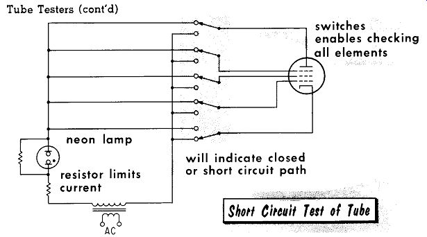
--------- … neon lamp resistor limits current n AC will indicate
closed or short circuit path switches enables checking all elements
To test for short circuits between the tube elements, an a-c voltage is applied across any two of the tube elements. In series with the voltage is a neon lamp. When any two elements are shorted there will be a complete path, and the neon lamp will indicate a closed or short circuit path. To enable checking between all elements, individual switches are used. A resistor is placed in series with the neon lamp to limit the current. Another resistor is shunted across the neon lamp to prevent the lamp lighting from a small charging current that may pass through the tube interelectrode capacities.
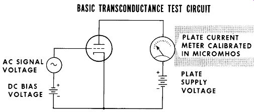
-------- AC SIGNAL VOLTAGE DC BIAS VOLTAGE BASIC TRANSCONDUCTANCE TEST CIRCUIT,
CURRENT METER CALIBRATED IN MICROMHOS
A mutual conductance test places a tube in a basic circuit as shown. The same tube voltage used by the tube manufacturer to establish the tube ·s ratings will be applied. Mutual conductance is the ratio of change in plate current to the change in grid voltage. The grid signal voltage can be changed by a known small amount such as 1 volt. Reading the plate cur rent change will indicate whether the tubes transconductance is the same as that given by the tube manufacturer.
Tube Tester Circuit
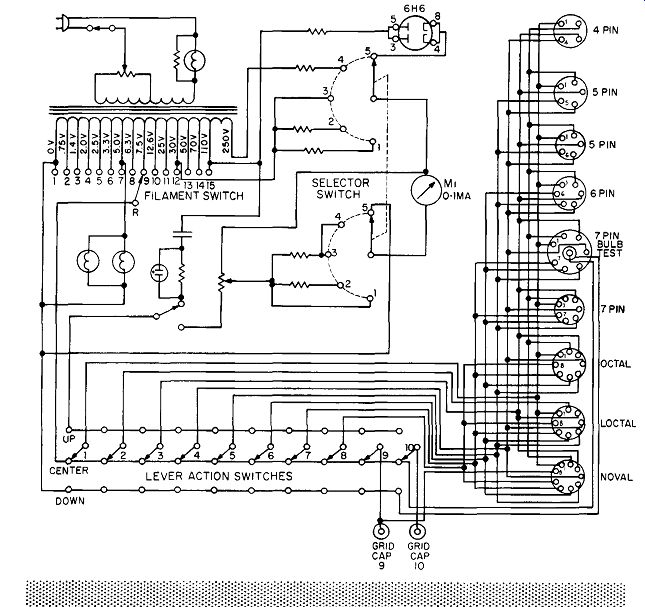
A commercial, emission-type tube-checker circuit is illustrated below. The complex switching circuits are necessary to place the proper voltage to any pin of any tube socket, and to tie together all elements, other than the cathode, in order to test emission.
-----------
A signal generator is essentially a substitute radio station used to generate radio frequencies in the broadcast band and higher frequencies.
The basis of an r-f signal generator is a variable frequency oscillator.
Harmonics of the fundamental frequencies are used to obtain the higher frequencies.
In addition to the r-f signal, a modulating audio frequency of 400 or 1000 cycles must also be available. The audio frequency can be used in dependently as a substitute audio signal or to modulate the r-f signal generator output.
With faulty tubes causing an estimated 70% of receiver troubles, tube testing becomes important.
The best test of a tube is to replace it with a known good tube of the same type. However, with the large number of tube types available, this would be difficult.
The two most popular type tube tester circuits are the emission type and dynamic mutual conductance type.
In addition to the test for emission or conductance, all tube testers must check for internal short circuits between the tube elements.
To test a tube for emission all elements aside from the cathode and heater are tied together and a voltage applied between the elements and the cathode. The resulting plate current flow indicates the value of cathode emission.
To test a tube for mutual conductance it is placed in a basic amplifier circuit. The grid signal voltage is changed by only a small amount: the resulting plate current change indicates whether the tube's mutual conductance is the same as that given by the manufacturer.
To test for short circuits between elements, a neon lamp in series with an a-c voltage is placed across the tube elements. A short circuit will cause the neon indicator to glow.
REVIEW QUESTIONS
1. The r-f signal generator is used to align what tuned radio circuits?
2. Describe one method used to have the audio oscillator modulate the r-f signal of the signal generator.
3. What is the purpose of the blocking capacitor at the audio and r-f signal output jacks?
4. What is the basic method of changing bands of frequencies in the r-f signal generator?
5. What is a good precaution to follow when applying the output of the signal generator to a receiver?
6. With both an emission and dynamic mutual conductance tester avail able, which would be preferable?
7. In testing a tube for emission, it is connected as a diode. Why?
8. With only one neon lamp short circuit indicator, how are the multiple elements of a tube tested for individual short circuits?
9. The plate current meter calibrations read in a mutual conductance tube tester are calibrated in what values?
+++++++++++++++++++
Cathode Ray Oscilloscope-Cathode Ray Tube
The Cathode Ray Oscilloscope is an invaluable servicing tool used to display a-c voltage waveforms. Taking the a-c voltage present at any point, it will convert this voltage to a visual display of the voltage waveform on a Cathode Ray Tube (CRT) that is most often five inches in diameter. This large, visual waveform display allows constant observation as to whether the voltage present is of the proper amplitude, has the correct waveform, and whether it is remaining constant or is varying.
The heart of the oscilloscope is the Cathode Ray Tube. In the basic tube the electrons emitted from the cathode are attracted by the high positive potential of the anode. The anode is circular in shape with a small hole in the center. The high potential of the anode causes the electrons to accelerate to a high speed. Most of the electrons will strike the anode, however, a sufficient number will go through the hole as a beam, and continue on to the front or faceplate of the tube.
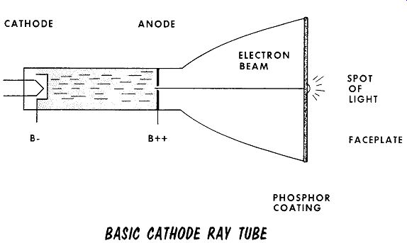
---- CATHODE B ANODE B ++ ELECTRON BEAM PHOSPHOR COATING BASIC CATHODE RAY
TUBE SPOT OF LIGHT FACEPLATE
The face of the tube is coated with a phosphor that converts the energy of the electron beam to a spot of light. The property of the phosphor emit ting light when struck by an electron beam is called fluorescence. The type of phosphor used determines the type of glow emitted by the face of the tube. For use in oscilloscopes, the color is usually green, although other colors are available for special purposes. After the beam of electrons is removed, the spot of light will remain on the face of the tube for a short time. This is called its persistence. For rapidly-changing waveforms a short-to-medium-persistence phosphor is required.
Cathode Ray Oscilloscope-Cathode Ray Tube (cont’d)
A cylindrical cathode is slipped over a non-inductively wound heater to provide the large numbers of electrons required to form a beam. The flat end of the cathode sleeve is liberally coated with an oxide for copious electron emission. The control grid is a larger cylindrical sleeve, similar to the cathode, containing a small hole at the end. The grid completely encloses the cathode permitting the value of grid bias to provide control over the electron flow as in a conventional tube, This controls the number of electrons striking the face of the tube, which in turn controls the intensity of the light.
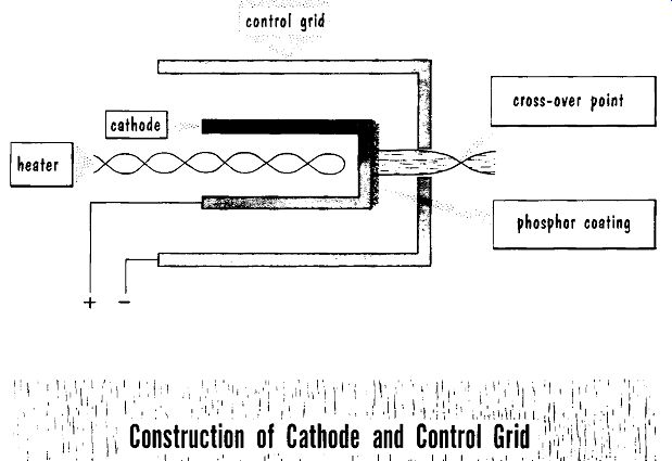
---------- control grid cross-over point phosphor coating
In addition to controlling electron flow, the shape and placement of the grid allows focusing of the electron beam. Due to the difference in potential between the control grid and cathode, an electrostatic field is developed.
The lines of force of this field act to converge the scattered electrons, causing the majority of electrons to pass through the hole in the end of the grid and converge or focus at a crossover point. This is called electro static focusing, and is analogous to an optical lens focusing light rays.
------
Cathode Ray Oscilloscope-Cathode Ray Tube ( cont’d)
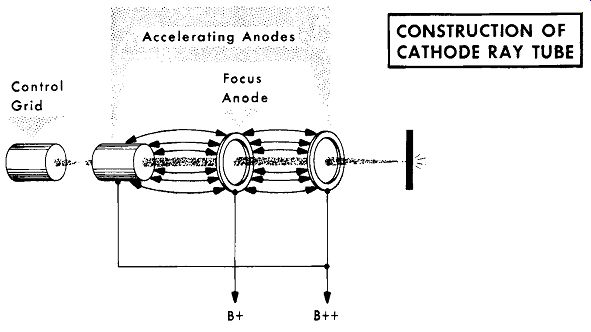
Control Grid Focus Anode B+ B ++
CONSTRUCTION OF CATHODE RAY TUBE
To accelerate and focus the beam for a bright sharp spot the beam is passed through a split accelerating anode and a focus anode. The accelerating anode is placed at a very high potential, a typical value being 2000 volts.
(This is a good place to remind you to observe safety rules when working with these voltages.) The high potential of the accelerating anode accelerates the electrons in the beam to the high velocity required to have the phosphor glow when struck by the speeding electrons. The focus anode being at a lower potential provides the desired electrostatic field between it and the accelerating anode on either side. Varying the focus anode voltage varies the shape of the electrostatic field, resulting in the electron beam converging and crossing over at slightly different points close to the tube's face plate. With the correct setting the beam will converge directly on the phosphor coating to provide a sharp clear spot of light. Incorrectly set, the crossover point will be before or after the phosphor coated face plate, resulting in a large, blurry blob of light.

---- correct crossover point results in a sharp spot incorrect
crossover points result in blurred spot
Cathode Ray Oscilloscope-Control Voltages
Control voltages are applied to the deflection plates to move or deflect the beam. Going back to one of the basic principles of electricity-like charges repel, un-likes attract-we use a negative charge to repel, and a positive charge to attract the electron beam.
The action of the deflection plates is identical for both vertical and horizontal deflection. Taking first the action of the vertical deflection plates: With one of the vertical deflection plates at ground potential, a negative potential is applied to the opposite plate. As the electron beam goes by the deflection plates, the negative, electrostatically charged plate will repel the beam, deflecting it towards the bottom of the faceplate. Changing the charge and placing a positive electrostatic charge on the deflection plate will cause the beam to be attracted towards the deflection plate. This deflects the beam towards the top of the faceplate. Varying the voltage of the vertical deflection plates from a negative value, through zero to a positive value will draw a vertical line on the faceplate of the cathode ray tube.
The action of the horizontal deflection plates is identical.
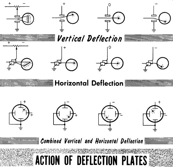
-------
-Horizontal Deflection
ACTION OF DEFLECTION PLATES
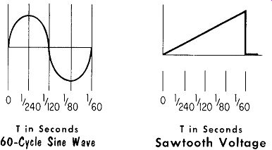
--------- Cathode Ray Oscilloscope-Signal Display T in Seconds 60-Cycle
Sine Wave
T in Seconds Sawtooth Voltage
The main task of an oscilloscope is to display a-c waveforms. For simplicity, a sine wave (see illustration) will be used for purposes of explanation; however, in practice the most complex waveform may be displayed.
A sine wave is most often drawn as shown above, in a vertical manner. To have it reproduced or traced in this manner on the face of the cathode ray tube, we apply the sine wave to the vertical deflection plates. This is not enough, however, as a moments thought will remind us that it will merely "pull-and-push" the beam in a vertical manner, resulting in a straight vertical line on the face of the tube. To have it draw the sine wave horizontally, from left to right, and vertically, from top to bottom, we must ...
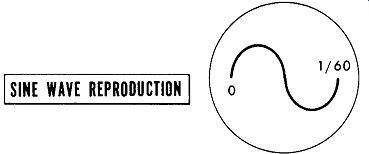
--------- SINE WAVE REPRODUCTION
... "pull" the beam both left to right and up and down (looking at the front of the tube) in the same length of time it takes the sine wave to complete one cycle. To do this we apply a voltage to the horizontal deflection plates that, starting at zero, increases to maximum in a steady (linear) increase with time. This pulls the beam horizontally across the face of the tube at the same time the sine wave signal applied to the vertical plates goes through one cycle.
The electron beam must then immediately return to its starting point. If not the beam will draw or trace another copy of the sine wave as it returns to the starting point. This is called a retrace. To have the beam instantly return to the starting point, the voltage applied to the horizontal deflection plates goes from maximum to minimum in the shortest possible time. The resulting shape of the voltage applied to the horizontal deflection circuit appears as a tooth in a handsaw, and, accordingly, is called a sawtooth voltage.
Cathode Ray Oscilloscope-Sawtooth Oscillator
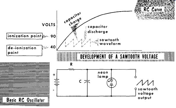
To develop a sawtooth voltage, we take advantage of the charge and discharge of a resistor-capacitor combination ( discussed in Volume 2 of Basic Radio). In the charging curve of a capacitor, see illustration, the initial portion of the curve is linear. The sawtooth oscillator circuit is used to charge a capacitor, then discharge it to form a sawtooth waveshape.
The neon gas-filled tube exhibits a high resistance with a low voltage across it. When the voltage across the tube reaches the correct value (approximately 90 volts for a type NE-2), the high voltage pulls electrons from the gas atoms. The atoms that lost an electron become positive ions. The freed electrons will rush to the positive electrode and the positive ions to the ...
-------
... negative electrode. This results in ionization of the tube and a correspondingly heavy current flow. In its ionized condition the tube represents a virtual short circuit. The tube will remain this way until voltage across it drops to about 40 volts (for a type NE-2), when the tube will de-ionize - return to its normal state - and again exhibit a high resistance.
The neon tube is placed parallel to the charging capacitor in the circuit.
The charging voltage across the capacitor bui1ds up to 90 volts, and the neon tube ionizes. The ionized tube presents a short circuit across the capacitor. The capacitor discharges through the tube - almost instantaneously. The voltage across the capacitor starts to drop to zero; however, at 40 volts the tube de-ionizes to present an open circuit. With the short circuit removed, the capacitor again starts to charge to repeat the cycle.
The frequency of the oscillator can be changed by changing the value of R or C, changing the time required for the capacitor to charge to the ionization voltage.
Cathode Ray Oscilloscope-Sawtooth Oscillator ( cont’d)
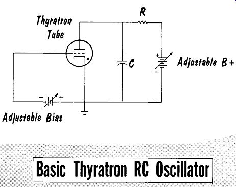
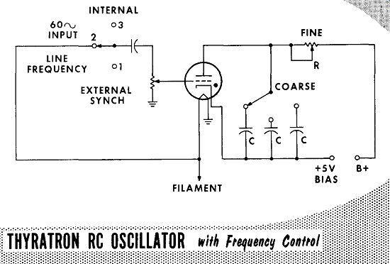
The neon tube is not very stable, and the required ionizing voltage varies between tubes. A gas-filled triode tube, a thyratron, is an improvement over the neon tube. The action of the thyratron is the same as the neon tube with these important exceptions: a cathode is used as a source of electrons. The gas employed, mercury or argon, is more reliable than neon.
The firing point is under control by the addition of a grid. The thyratron oscillator circuit provides methods for changing its frequency, changing the R in the RC circuit, changing the C in the RC circuit, changing the applied B+ voltage, and changing the grid bias voltage.
-------
The ionization of the thyratron can be controlled by applying the signal voltage to the grid. This permits the sawtooth oscillator to act as a sweep circuit which sweeps the beam across the face of the tube in step with the signal under observation. This is called synchronization. Applying the signal under observation to the grid of the thyratron causes it to act as a trigger. keeping the thyratron in step with the signal. When the signal voltage on the grid goes sufficiently positive, the thyratron will ionize.
This will place the horizontal-deflection-plate sawtooth signal in step with the 60-cycle sine wave or other signal under observation. A small fixed value of external bias is used in the cathode circuit.
Cathode Ray Oscilloscope-Sawtooth Oscillator ( cont’d)
Provisions are made for varying the time constant set by the values of R and C of the oscillator circuit. Switching circuits are used to change the value of the capacitor in the circuit, and a potentiometer is used to ...
-------
... vary the resistance. The switch that changes the capacitor is called the Coarse or Range switch because it sets the C of the RC circuit roughly to the desired range of frequencies. The potentiometer is called the Fine, Fine Frequency, or Frequency Vernier since it sets the R of the RC circuit close to the desired frequency.
Note the three positions of the switching circuit in the grid of the thyratron oscillator. In position 1, the switch is set for External Synchronization.
This enables the firing of the thyratron to be synchronized with an external signal voltage. In position 2, the switch is set for Line Frequency. This is a 6.3-volt, a-c sine-wave voltage from the filament circuit. Whenever a 60 cycle signal, or multiple of 60 cycles is used, it will synch readily at the grid of the thyratron. In position 3, the switch is set for Internal. This takes a portion of the signal under observation and applies it to the grid of the thyratron tube, synchronizing the oscillator with the signal.
Cathode Ray Oscilloscope-Sweep Display
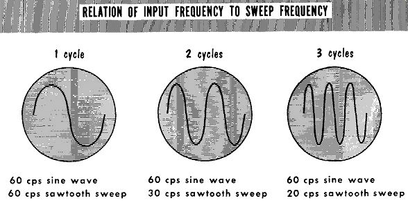
As discussed previously, the time value necessary to charge the capacitor is equal to five time constants. One time constant is t =R X C. The larger the values of R and C, the longer it takes to reach the ionization voltage of the thyratron. Therefore, for low frequencies we use larger values of R and C, and, conversely, we use smaller values of R and C for higher frequencies. The most popular method to control the frequency of the saw tooth voltage is to switch to different values of capacitors as a rough, or coarse adjustment, and use a variable resistance as a fine adjustment.
----------
RELATION OF INPUT FREQUENCY TO SWEEP FREQUENCY 1 cycle 2 cycles 3 cycles 60 hz sine wave 60 hz sine wave 60 hz sine wave 60 hz sawtooth sweep 30 hz sawtooth sweep 20 hz sawtooth sweep
In actual practice the input signal or sawtooth sweep voltage is not sufficient to deflect the beam completely across the face of the CRT. To over come this obstacle, amplifiers are used between the signal input and the deflection plates. The vertical amplifier, and, to a lesser degree, the horizontal amplifier must meet special requirements. They must respond to a wide band of frequencies, and have high gain to provide sufficient signal voltage to drive the beam completely across the face of the tube. The gain of the vertical amplifier will determine the sensitivity of the instrument.
The higher the gain, the weaker the signal input required to provide sufficient sweep across the face of the tube.
Often the signal to be observed is not sufficient to couple directly to the deflection plates. However, it is large enough to overload and cause distortion. To prevent this an attenuator may be placed at the input of the amplifier.
The attenuator is a carefully designed voltage divider with compensating circuits that prevent loss of high frequencies. Using a switch, it is possible to tap-off a sufficient portion of the signal across the divider and feed it to the amplifier, providing sufficient signal without overloading. Attenuator switches are usually calibrated in units of 10, 100, 1000, etc.
Cathode Ray Oscilloscope Diagram
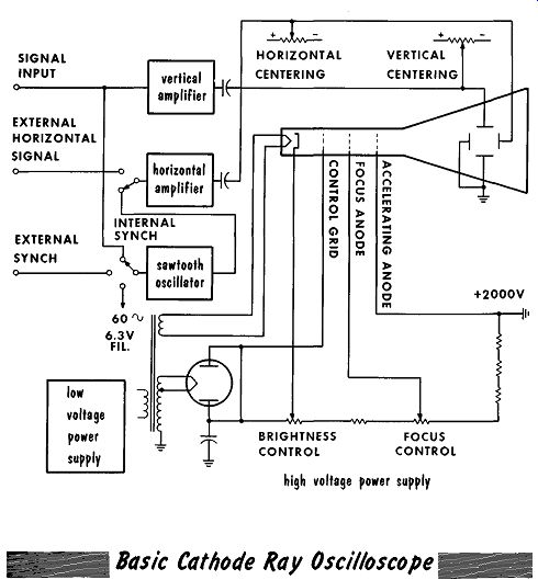
The combined block and schematic diagram of a basic Cathode Ray Oscilloscope illustrates the high voltage power supply. Note, that it is a negative-output power supply with the positive end at ground. Tying the heater to the cathode places the heater at the same potential as the cathode.
If this had not been done the heater would be at a difference in potential to the cathode of almost 2000 volts, and would cause an arc-over between the cathode and heater. A variable bias voltage is applied to the deflection plates to center the beam on the face of the tube.
---
--------- Cathode Ray Oscilloscope
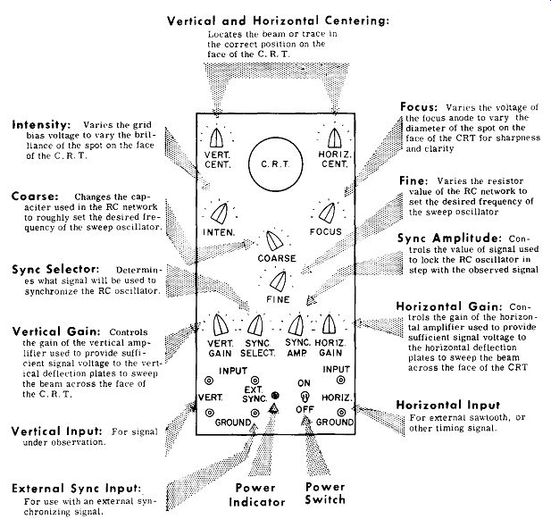
Controls Intensity: Varies the gnd bias voltage to vary the brilliance of the spot on the face of the C.R. T.
Coarse: Changes the capacitor used in the RC network to roughly set the desired frequency of the sweep oscillator.
Sync Selector: Determines what signal will be used to synchronize the RC oscillator.
Vertical Gain: Controls the gain of the vertical amplifier used to provide sufficient signal voltage to the vertical deflection plates to sweep the beam across the face of the C.R. T.
Vertical Input: For signal under observation.
External Sync Input: For use with an external synchronizing signal.
Vertical and Horizontal Centering: Locates the beam or trace in the correct position on the face of the C.R. T.
Focus: Vanes the voltage of the focus anode to vary the diameter of the spot on the face of the CRT for sharpness and clarity Fine: Varies the resistor value of the RC network to set the desired frequency of the sweep oscillator
Sync Amplitude: Controls the value of signal used to lock the RC oscillator in step with the observed signal
Horizontal Gain: Controls the gain of the horizontal amplifier used to provide sufficient signal voltage to the horizontal deflection plates to sweep the beam across the face of the CRT For external sawtooth, or other timing signal.
Signal Tracer
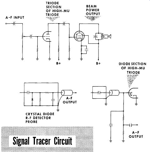
A signal tracer allows testing for the presence or absence of a signal in a receiver circuit with the receiver operating. The use of a built-in detector permits tracing the signal from the antenna through the r-f and i-f stages to the detector circuits. After the detector the tracer is used as an audio amplifier to follow the signal through the a-f stages to the speakers.
-------
The signal tracer consists of an audio amplifier with two probes. The audio-signal tracer probe contains only a blocking capacitor used to couple a-f signals to the audio amplifier. For tracing r-f and or i-f signals, a detector is used ahead of the input to the signal tracer's audio amplifier. The detector can be mounted directly in the probe as shown, or it can be the diode portion of a duo-diode high-mu triode.
Grid-Dip Meter
-------
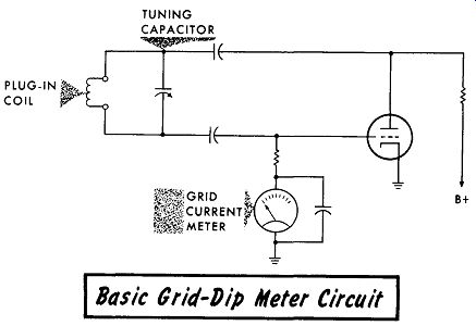
The grid-dip meter, also called a grid-dip oscillator, will indicate the resonant frequency of an LC circuit. The grid-dip meter is a tuned oscillator with a current-reading meter placed in the grid circuit. The oscillator tuning-circuit coil is a plug-in type that mounts on the outside of the instrument case. The grid-dip meter coil is placed close to the tuned circuit being checked. The grid-dip meter is then tuned through the frequency region of the tuned circuit being checked. When the grid-dip meter oscillator frequency is identical to that of the tuned circuit being checked, some of the energy of the oscillator will be absorbed by the circuit being checked. This loss of energy is indicated by a reduction (dip) in the grid circuit-current indicating meter, hence the name grid-dip meter. Calibrating the tuning capacitor dial in several bands of frequencies to match the various plug-in coils, allows a wide frequency coverage.

--------
The Cathode Ray Oscilloscope is used to display a-c voltage waveforms. It allows observation of the voltage for amplitude, waveform, and whether it is constant or varying.
The heart of the oscilloscope is the cathode ray tube (CRT). The face of the tube is coated with phosphor chemicals that convert the energy of an electron beam to a spot of light.
To accelerate and focus the beam of electrons, they are passed through an accelerating anode and a focus anode. The accelerating anode is at a high potential, as much as 2000 volts. The high voltage requires observation of safety rules.
The focus anode is at a lower potential than the accelerating anode, creating an electrostatic field between them. Varying the focus anode voltage varies the field to provide focusing action.
Control voltages are applied to the deflection plates to deflect the electron beam.
A combination of voltages on the vertical and horizontal deflection plates will allow the electron beam to draw any desired pattern on the face of the cathode ray tube.
To pull the electron beam steadily (linearly) across the face of the tube and then have it instantly return to the starting point, requires a sawtooth voltage applied to the horizontal deflection plates.
To develop a sawtooth voltage oscillator, we use the charge and discharge of a resistor-capacitor combination in addition to a neon tube.
The frequency of the sawtooth voltage oscillator can be varied by changing the value of R or C. An improvement over the neon tube is a thyratron, which uses a cathode, a control grid (another method for changing frequency), and a more reliable gas.
Applying the signal under observation to the grid of the thyratron causes the signal to act as a trigger and provide synchronization of the oscillator and signal.
When the frequency of the sawtooth oscillator is the same as the signal under observation, one cycle of the signal will be displayed.
REVIEW QUESTIONS
1. What determines the color of the spot of light on the face of a CRT?
2. What is meant by persistence of a cathode ray tube?
3. Briefly describe electrostatic focusing.
4. What will be the results of applying a sine wave signal to the vertical deflection plates?
5. Describe a retrace.
6. What portion of an RC curve is used in a sawtooth oscillator?
7. Briefly describe ionization of 3. neon tube.
8. Two controls are used to change the frequency of a sawtooth oscillator: Coarse or Range, and Fine Frequency or Frequency Vernier.
Briefly describe the action of each control.
9. What is mean by external synchronization?