Automobile radio-receiver repair is perhaps the most neglected yet lucrative area in the field of receiver repair. Repairing auto radios requires additional time, mainly for the removal and installation of the receiver. Because of the extra time, extra charges have to be made which would not be encountered in home radio repairs.
An important adjunct in obtaining a large auto-radio repair trade is a convenient, enclosed parking and drive-in facility so that the work can be done in any weather. Some special tools, similar to those used by auto mechanics, are helpful - a set of ratchet wrenches ranging from ¾-inch to ¾-inch, open end and box wrenches ranging from ¾-inch to ¼-inch, etc.
---------
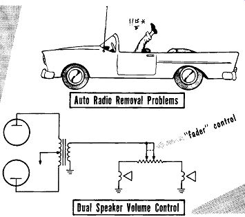
Auto Radio Removal Problems
Dual Speaker Volume Control
One of the most vexing problems in auto radios is illustrated above. This is the persistent effort of automobile manufacturers in making it a battle of wits and patience to remove an automobile radio.
An innovation that has become standard in many automobiles is a rear-seat speaker in addition to the speaker mounted on the dash board. The rear seat speaker is usually switched in and out of the circuit by a three-way switch that selects either the front speaker, rear speaker, or both.
Another method of controlling the front and rear speaker is with a special fader control, as shown, which is a special volume control with two ganged adjustable taps. By moving the control in one direction, one speaker in creases in volume while the other speaker decreases. When the control is set at an extreme end position, one speaker will be at full volume, and the other speaker will be turned off. At the center position both speakers will receive equal volume.
R-F Amplifier Stage
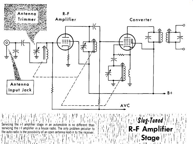
Automobile radios have disadvantages -- they must operate with a short whip antenna, and they often operate at long distances from the broadcasting station. To overcome these disadvantages the majority of auto radios have a stage of r-f amplification. A typical r-f amplifier circuit used in an auto radio is shown. The circuit features variable inductance tuning (slug tuned) which is prevalent in auto radios. Slug tuning is better suited for the vibration and shock encountered in an auto radio. The plate circuit of the r-f amplifier stage is tuned with the output signal RC coupled to the r-f grid of the converter.
To aid in aligning the r-f amplifier to the short antenna, either a special trimmer capacitor, or the tank-circuit trimmer capacitor is made accessible through a capped hole in the side of the receiver. To align the circuit, the auto receiver is tuned to a weak signal at the high end of the band, approximately 1400 khz and the trimmer is set for maximum output.
Antenna Input Jack
Servicing the r-f amplifier stage in an automobile is no different than servicing the r-f amplifier In a house radio. The only problem peculiar to the auto radio is the. possibility of an open antenna lead into the receiver.
R-F Amplifier
---------
The auto antenna, although a separate item mechanically, is electrically part of the r-f stage. Antennas are usually installed by the automobile dealer when the automobile is purchased. However, replacements are an important item since the antenna is exposed to the weather and other hazards. A substitute antenna on the service bench need only be a short length of wire with an antenna plug at one end.
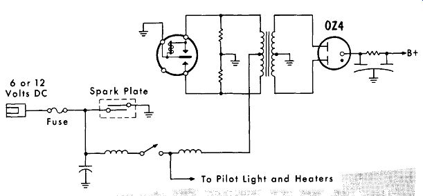
Power Supply 6 or 12 Volts DC Spark Plate
Fuse
1 To Pilot Light and Heaters
AUTO-RECEIVER VIBRATOR TYPE POWER SUPPLY.
--------
It has been said that perhaps 95% of the difficulties in an auto radio are in the power-supply stage, see figure; this is probably true. The output d-c voltage, filter circuit will usually have low capacity rectifiers. The a-c frequency of a vibrator is usually 115 hz; the full-wave-rectifier ripple frequency is thus 230 hz, requiring less capacity for adequate filtering.
In many receivers the rectifier tube is a type 6X4, or a similar rectifier tube with a separate heater and cathode. Although the cold-cathode type 0Z4 rectifier has many advantages, it can become fussy as it gets older by not always firing when the receiver is first turned on. Racing the car motor will usually increase the generator output voltage and the voltage applied to the receiver by a small amount, helping to fire the 0Z4 rectifier. When this occurs the rectifier should be replaced.
A common difficulty is intermittently "blowing" open the fuse. This results from either of two troubles, or a combination of both. A worn vibrator with pitted points will have a tendency to arc as it operates. Occasionally the arc will cause the points to weld together, causing excessive current drain that will quickly blow the fuse. Giving the vibrator a sharp tap will temporarily free the points. A bad buffer capacitor quite often is the contributing cause to bad vibrator points. As a result changing the vibrator without changing the buffer capacitor is an invitation to a quick repeat performance of a defective vibrator. Vibrator manufacturers often guarantee the replacement vibrator only if the buffer capacitor is replaced at the same time.
An aid in checking troubles is in listening carefully for the vibrator buzz.
Many vibrators are well isolated and clamped with a piece of sponge rubber to quiet them. If it is not buzzing, the fuse is not blown, and if the pilot light and tubes are lit, the difficulty is in the vicinity of the vibrator.
To check an auto-radio power supply with no voltage output, listen for the buzzing of the vibrator. If it is not buzzing, test the fuse; if the fuse is good, check the applied battery voltage through to the on-off switch. The high value of current flowing through the switch is a common cause in its opening or burning out. Be sure the spark plate or filter capacitor is not shorted, and check for an open filter coil. Voltage should be present at the center tap of the primary of the transformer. To check the transformer the battery voltage should be present at both ends of the primary winding and at the vibrator. points. The vibrator should be checked by replacing it with a good substitute.
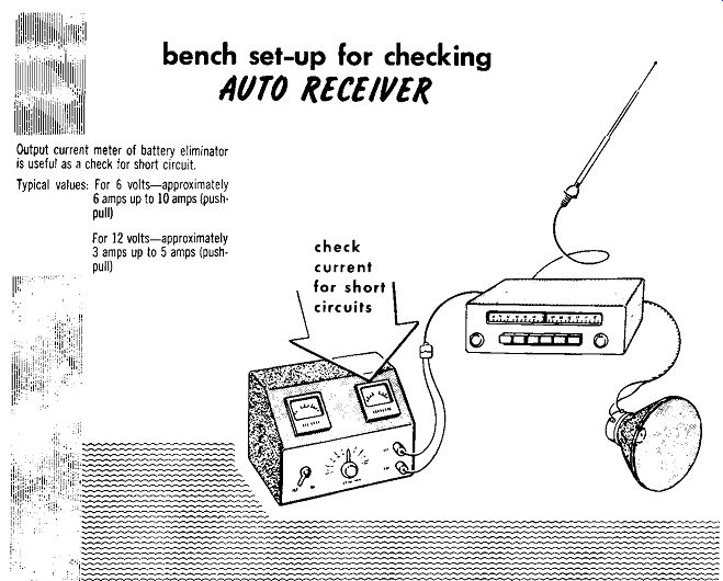
bench set-up for checking AUTO RECEIVER
---------
If the vibrator is buzzing, check for high-voltage ac to the rectifier plates, being sure that the center tap of the secondary is at ground. If no d-c voltage is present at the cathode, the rectifier tube should be checked by replacement with a substitute. With a good rectifier tube, a loss of output voltage could then be either a shorted filter capacitor or an open filter resistor.
Low output voltage from the power supply could be due to a leaky buffer capacitor, a defective rectifier tube, or leaky filter capacitors. Should the filter resistor change and increase in value, the output voltage would also be reduced.
Signal Seeker
The signal seeker is a special circuit in which pressing a button on the radio panel will tune the receiver to the next station. If this station is not desired the button can be pressed again to seek the next station on the dial, etc. To prevent the receiver from tuning in on all stations, a sensitivity control causes the signal seeker to stop only at the more powerful local stations.
To operate the tuning circuit a spring-powered motor is used. Mounted on the motor shaft is a paddle wheel that serves two purposes: The large air resistance of the paddle wheel acts as a speed governor, and a relay-actuated latching arm locks the paddle wheel when the desired station is in tune.
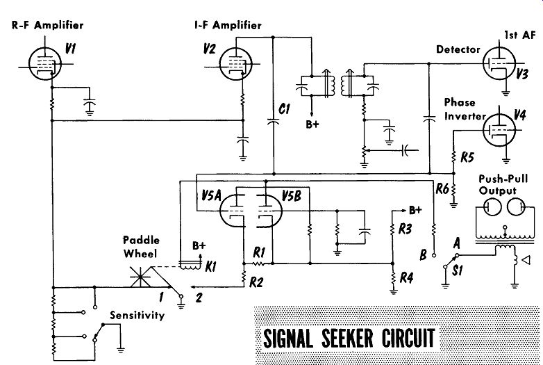
A typical signal seeker circuit is shown. Resistors R3 and R4 comprise a voltage divider supplying bias for tubes VS A and B. When on station the paddle wheel is locked in position, and the cathode of V5A then gets its bias through R1. Relay K1, in the plate circuit of V5B has a small amount of current flowing through it, but not enough to actuate the latching arm.
To initiate the signal seeking action, the button on the front panel is pressed, momentarily changing S1 from position A to B. In position B the secondary of the output transformer is opened and the receiver is muted.
In addition, a path for the B plus applied to relay K1 is now available through S1B to ground, actuating the relay.
With relay K1 actuated the latching arm is moved away from the paddle wheel, and the spring motor then tunes the receiver to seek a new signal.
At the same time the latching arm removes the ground from contact #1.
The cathodes of V1 and V2 now return to ground through the sensitivity switch. The setting of the sensitivity switch determines the bias for V1 and V2, in turn determining the sensitivity of the receiver for the stations received.
With the latching arm grounded through contact 2, resistors R1 and R2 are now parallel to bias resistor R4. The parallel circuit divides the voltage, reducing the cathode bias of both tubes. Because of the low plate voltage of V5A the tube remains cut-off. The high plate voltage of VSB and the reduced bias causes it to conduct heavily, keeping relay K1 actuated. Al though S1 is pressed momentarily to initiate the actuation of relay K1, the heavy current flow through VSB will keep the relay actuated when S1 is released.
When tuning in on a station the signal provides a rectified A VC voltage that is developed across resistors R5 and R6; this is applied as bias to the grid of V5A. At the same time, the i-f signal is coupled to the grid of V5A through C1. As the station is being tuned in, the positive-going portions of the i-f signal will reach an amplitude that overcomes the bias and triggers tube V5A into conduction. The relationship of the A VC bias voltage and the amplitude of the i-f signal is carefully set to cause tube V5A to conduct just before the signal is tuned to maximum at the center frequency. This relationship remains the same regardless of the strength of the signal being tuned.
------- R-F Signal Seeker
When V5A conducts, the negative-going plate connected to the grid of VSB, will cause tube VSB to cut-off and stop conducting. With V5B non conducting, relay, K1 is de-energized and the ratchet snaps back to lock the paddle wheel and stop the tuning motor.
Tube V SA is triggered at the correct moment before the signal is completely tuned in to the center frequency. This in turn causes tube V5B to cease conducting and lock the paddle wheel. The small time delay between the initiation of this action, plus the inertia of the spring motor, will result in the station being tuned to the center frequency when the tuning motor stops.
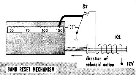
When the tuner reaches the high frequency end of the dial, it automatically closes S2, energizing the solenoid K2. Solenoid K2 returns the tuner to S2 the low frequency end of the band. At the same time, while moving the tuner away from the high end of the band, a spring opens S2, de-energizing the solenoid. When the solenoid moves the tuner it also winds the spring power motor.
To check for this the receiver should be set for manual tuning to determine if any signal is being received. A defect in the tuned stages that will cause a weak signal will cause the signal seeker to stop at only the very strong signals, if at all.
------------
In servicing the signal seeker of the type shown, all voltages should be checked to coincide with the listed values. The tubes should be checked if the signal seeker does not stop at a station or does not keep the locking ratchet relay energized while seeking a station. If closing S1 does not energize relay K1, check for an open relay coil or a defective tube VSB. If the signal seeker does not stop tuning with an adequate input signal, check tube V5A. If C1 is open, or there is a loss of A VC voltage from R5 and R6, tube V5A will not trigger.
Ignition Interference
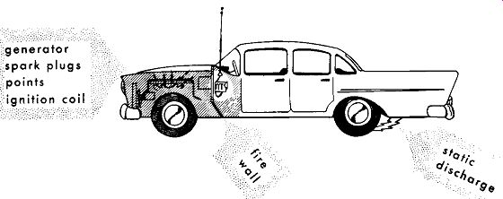
Mounting the receiver in the passenger compartment with the fire wall acting as a shield, is an aid against interference caused by the arcing at the spark plug points. The antenna is mounted clear and free of the car with the sheet metal of the car acting as a shield. The antenna lead-in is shielded to prevent noise pickup where the lead-in runs through the car. The remaining problem is the lead bringing the voltage from the battery. The battery is common to both the radio and the ignition system and has a large value of noise pickup. Filter circuits are placed at the voltage-input terminal of the receiver to remove this noise. The filter circuits incorporate low-resistance chokes to suppress the high-frequency interference. Special spark plate capacitors also help filter the interference. With all these precautions interference from the ignition system becomes a minor problem.
There is still the possibility of ignition noise becoming a problem from either a car's ageing, or operating the receiver in remote locations with weak signals. To remove ignition noise from the distributor points, a suppressor resistor is mounted in the high-voltage lead just as it enters the distributor. An incorrect spark plug gap could cause interference. The gap should be checked and correctly set by a competent automobile serviceman.
------
If the gap is correct, spark plugs using built-in resistors can be used for additional noise suppression. A high-pitched whine that changes with the motor speed indicates arcing at the generator brushes. To help quench this arc a capacitor is mounted on the generator case with one foil grounded to the case, and the other foil placed at the armature terminal.
Static electricity that is discharging from the wheels to the car frame, results in a periodic popping sound on the radio. The static electricity builds up due to the wheel rims or brake drums being insulated from the ground by the tires, and having a poor ground return to the car frame.
To overcome this problem, special conducting powder is blown inside the tire and tube to discharge the static electricity through the tires.
SUMMARY
Auto radio repair requires additional time for the removal and installation of the receiver.
Tools similar to those used by auto mechanics are helpful in removal, installation, and servicing of automobile receivers.
A popular item used in many cars is a rear seat speaker controlled by a three-way switch or a fader control.
Automobile receivers operate under disadvantages: they use a short antenna and may have to operate at long distances from the radio station.
Because of vibration and shock, most automobile receivers use slug tuning.
To help align the r-f amplifier stage to the short antenna, a trimmer capacitor is accessible through a capped hole in the side of the receiver.
The greater majority of difficulties in an automobile receiver occur in the vibrator-operated power supply.
The power-supply filter capacitors are of smaller capacity because of the higher ripple frequency in a vibrator power supply.
A common difficulty is intermittent "blowing" fuses because of worn vibrator points, a defective buffer capacitor, or both.
An audible buzzing sound is an aid in checking the operation of a vibrator.
High-value current will often burn out the on-off switch.
The signal seeker is a special circuit which tunes the receiver to the next station by pressing a button or bar on the radio panel.
A sensitivity control is used to prevent the receiver from tuning in all stations including undesired weak stations.
A spring-powered motor operates the signal seeker tuning circuits.
The use of r-f filter chokes, and special spark-plate capacitors at the battery voltage input lead to the receiver helps reduce ignition interference to a minimum.
A common cause of ignition interference is an incorrect setting of the spark plug gap.
REVIEW QUESTIONS
1. What is an important help in being able to service automobile receivers in any type of weather?
2. Describe the operation of a fader control.
3. Why do the majority of automobile receivers employ a stage of r-f amplification?
4. What may be used as a substitute antenna for an automobile receiver being serviced on the bench?
5. Describe a common problem with the type OZ4 rectifier and how the problem is observed?
6. What symptom is indicated by intermittent fuse blowing?
7. Why must the buffer capacitor also be replaced when the vibrator is being replaced?
8. In the signal seeker circuit, what are the two purposes of the paddle wheel mounted on the motor shaft?
9. What device can be used to remove ignition interference caused by the distributor points of a car ignition system?