Servicing FM Receivers
The stages of an FM receiver are identical with those of an AM receiver.
An FM receiver differs mainly in the frequency of operation and the detector circuits. The operating frequency (88-108 me) of FM receivers finds the r-f and oscillator circuits using coils of only a few turns of heavy wire and tuning capacitors with only a few plates. The i-f tuned circuits usually operate at 10.7 mhz with adjustable inductance (slug tuned) i-f transformers. See below for a typical FM receiver circuit.
A block diagram of an FM receiver is shown in the illustration. Note the frequencies of the various stages. The detector stage can consist of a limiter-discriminator or a ratio detector. Although the ratio detector generally does not require a limiter preceding it, it may be found in some expensive models.
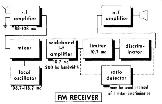
--------------- FM RECEIVER r-f amplifier 88-108 mhz mixer local oscillator 98.7-118.7
mhz; amplifier; 200 khz bandwidth; ratio detector; may be used instead of limiter-discriminator
The average FM transmitting station is a low-power (in comparison to AM) local station depending mainly upon line-of-sight reception for local coverage. Because of the low power, the majority of FM receivers incorporate an r-f amplifier stage and two i-f amplifier stages. A typical commercial FM receiver is shown. For centrally located receivers a built-in antenna is sufficient for good reception. For receivers located in fringe areas, an outdoor FM antenna is required. Since line-of-sight reception is the rule for FM operation, the outdoor antenna must be as high and as clear of obstructions, as possible.
Decoupling filters in the plate leads in the i-f and r-f stages of FM receivers are common. Many signal tracers will not operate at the frequencies encountered in FM tuned circuits. To isolate defective stages in an FM receiver, signal injection may be required.
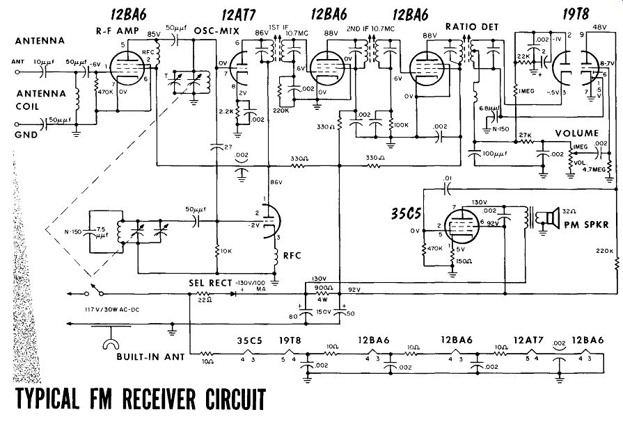
--------- TYPICAL FM RECEIVER CIRCUIT
FM Discriminator and Limiter
The discriminator is sensitive to AM as well as FM, and because of this the stage preceding the discriminator is a limiter stage used to remove amplitude variations. The limiter stage operates at low plate and screen voltage for sharp cutoff and quick saturation. Grid leak bias is used. The control grid of the limiter is a valuable check point - reading the value of the bias with a VTVM can determine whether any signal is present at the limiter grid. Should the input signal to the grid of the limiter below ...
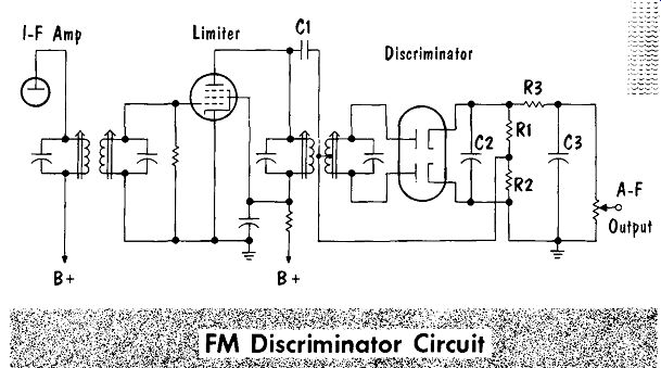
I-F Amp limiter; Discriminator B+ B + Rt R2 C3 A-F Output
... due to either a weak station or misalignment, the tube will not operate as a limiter but as an amplifier. With no limiting action a high noise level will be present with the detected signal.
Resistor R3 and capacitor C3 comprise the de-emphasis network. The detected signal voltage is developed across R1 and R2. At the center frequency the output voltages across R1 and R2 are equal but opposite, cancelling each other. With a modulated signal the difference voltage is taken from the top of R1 and developed across the volume control from where it is applied to the audio amplifier circuits.
With no audio output, the bias voltage at the grid of the limiter should be checked with a VTVM. If no bias is present, it can mean that either the preceding tuned stages are defective, feeding no signal, or that the limiter stage is defective. Voltage readings should be taken to check the limiter stage. With plate voltage present the primary of the detector transformer is presumed good. With plate and screen voltage present the tube should be checked by substituting a good tube. If the plate and screen voltages are correct and the tube checks good, lack of grid bias indicates loss of signal input to the grid.
A continuity check should be made of the secondary of the i-f transformer.
The grid resistor should be tested to see if it has opened and the grid capacitor should be checked for an open or short circuit. If all these tests indicate the limiter stage is operating correctly, then the difficulty is in the preceding stages. The action of a limiter is shown in the illustration.
With a signal applied, and the limiter stage working properly, the detector stage is checked for no output. Coupling capacitor, C1, should be tested for a short circuit. The continuity of the secondary of the discriminator transformer should be tested, including the center tap connection. The ...
INPUT FM SIGNAL VARYING IN AMPLITUDE; Input; LIMITER SYSTEM OUTPUT FM SIGNAL CONSTANT IN AMPLITUDE
Output
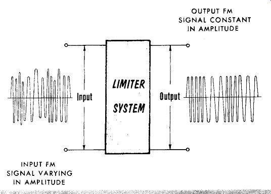
--------------
... detector tube rarely gives trouble, but it should be checked. Should capacitors CZ or C3 short, the signal will be lost. An open resistor – R1, R2, R3 -- or an open volume control can also cause a loss of the signal.
Low discriminator output accompanied by a high noise level and low grid leak bias of the limiter grid, indicates a weak input signal. The weak input, as previously mentioned, can be due to either a defect in the r-f or i-f tuned stages, or to misalignment. With an adequate input signal to the limiter, a low output could be caused by misalignment of the detector transformer, low emission of the detector tube, or high resistance leakage of C1, C2, or C3.
Ratio Detector
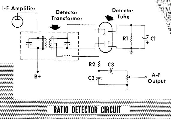
The reference voltage in a ratio detector is usually developed by a coil coupled to the detector transformer winding. The high value of R1 and capacitor C1 presents a large time constant that will quench any sudden change in voltage caused by noise or other amplitude changes. De-emphasis is provided by R2 and C2. The signal voltage developed across capacitor C2 is coupled to the volume control from where it is applied to the audio amplifier stages.
I-F Amplifier Detector Transformer
RATIO DETECTOR CIRCUIT
---
With no signal output from the ratio detector, the preceding i-f amplifier stage and detector stage should be checked by injecting a signal at the grid of the i-f amplifier stage. With a signal present in the preceding i-f amplifier stage and no detector output, the primary of the detector transformer is checked by checking the plate voltage of the i-f amplifier tube. The secondary of the detector transformer and the coupling coil should be tested for continuity. The detector tube should be replaced with a good tube. No output voltage would be developed if capacitor C2 should become short circuited. An open resistor R2 or open volume control would also cause the loss of the output signal.
A reduced output signal could be caused by misalignment of the detector transformer or low emission in the detector tube. A shorted time-constant capacitor, C1, would also cause low output. If capacitor C2 becomes leaky or resistor R2 increases in value, the result would be a reduction in the output signal. When R1 or C1 opens the signal may have a high noise level.
Gated Beam Detector
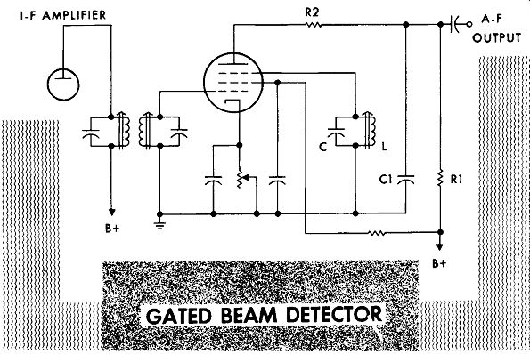
The special action of the gated beam tube and the tuned circuit in the quadrature grid, combine to provide FM detection. Plate current flows continuously regardless of signal conditions, permitting self bias by use of a cathode resistor. The setting of the cathode bias sets the operating point for the incoming signal. If the bias control is set to the wrong value, it will result in a high noise level. The output current pulses of the signal are integrated by R1 and C1 to provide an output signal voltage. Resistor R2 is used to improve the frequency response of the circuit.
---------
With a signal at the output of the preceding i-f amplifier stage and no detector output, the first step is to check all voltages. If the voltages check correctly, the tube should be replaced with a good substitute. To check the continuity of the secondary of the i-f transformer, the value of cathode bias voltage should be read with a voltmeter placed between the cathode and control grid. With an ohmmeter, a test should be made for an open coil or shorted capacitor, or possibly an open capacitor in the LC circuit of the quadrature grid. Should C1 short it would result in loss of plate voltage.
With a good signal at the plate of the preceding i-f amplifier stage but a weak output from the detector stage, check for reduced values of voltage at the plate and accelerator grids. If the i-f transformer is misaligned, it can cause reduced output. Check the cathode for proper bias.
FM Receiver Alignment
The instruments required for alignment are the r-f signal generator and vacuum-tube voltmeter. In alignment of FM receivers the popular method is to align the detector circuit, limiter circuit where used, followed by the i-f circuits and tuning circuits.
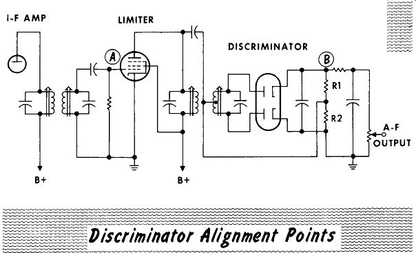
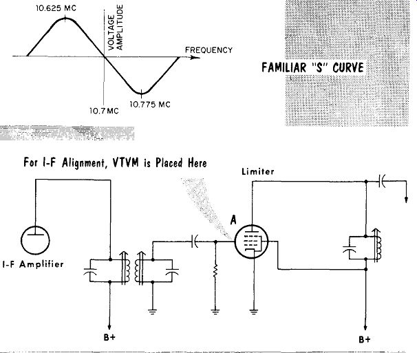
Proper alignment of the primary winding will adjust the linearity of the S curve. Balancing the output, and placing the intermediate frequency of 10.7 mhz at the center of the linear portion of the S curve, is the job of the secondary winding. The output of the generator is placed at the limiter grid, point A, in series with a 0.01-mfd capacitor. The VTVM is placed across R2, observing polarities. The output of the r-f signal generator is set to provide sufficient voltage drop across R2 for ease in tuning. The primary of the discriminator transformer is tuned for maximum output as indicated by the VTVM.
OUTPUT
----
The VTVM probe is then shifted from the top of R2 to point B to read the output voltage. The output of the discriminator transformer secondary is zero at resonance, which is difficult to read on a normal meter scale. To aid in tuning to zero, most VTVM's have a zero center scale to which the VTVM should be set. The secondary of the discriminator transformer is then tuned for zero output. To spot check the detector linearity, the output of the r-f signal generator may be shifted 50 khz above and below the resonant frequency. This should result in output voltages of equal value but opposite polarity.
Should an exact check be required, the output of the r-f signal generator should be varied in equal steps from 10.5 mhz to 10.9 mhz. Readings of the output voltage may then be plotted on a graph providing an S curve of the circuit.
----------
To align the i-f amplifier stages, the VTVM is placed in the grid circuit of the limiter, point A. The output of the r-f signal generator is placed at the r-f of the mixer or converter tube in series with a 0.01-mfd capacitor.
The i-f transformers are then aligned for maximum output as indicated by the VTVM. The order of alignment is to start with the output i-f transformer, followed by the interstage i-f transformer, if one is used, then alignment of the input i-f transformer.
The tuned r-f amplifier, converter or mixer, and oscillator circuits, are aligned for maximum output and correct tracking. The procedure is identical with that explained for AM receivers.
The ratio detector circuit may be of the balanced-detector type. The output of the r-f signal generator is placed at the grid of the output i-f amplifier stage, point A, in series with a 0.01-mfd capacitor. To align the primary of the detector transformer, the VTVM is placed across C1, observing
I-F Amplifier

---------
polarities. The primary of the detector transformer is aligned for maximum output as indicated by the VTVM. To align the secondary of the detector transformer in a balanced circuit, the VTVM is placed between point B and ground. The secondary of the detector transformer is then aligned for zero output.
In the unbalanced detector circuit, placing the meter from point D to ground does not provide zero readings. To obtain a zero reading the meter must be at the center of R1. To obtain this center tap, two 100K resistors are temporarily placed across R1 as shown. The center of these resistors, point C, is where the meter lead is placed to obtain a zero reading.
To align the i-f amplifier stages the VTVM is placed across C1, observing polarities. The output of the r-f signal generator is placed at the r-f grid of the mixer or converter tube in series with a 0.01-mfd capacitor. The i-f transformers are then aligned for maximum output as indicated by the VTVM in the same order previously mentioned for the discriminator-type receiver.
The gated-beam detector circuit has two adjustments. The cathode bias resistor is adjusted for a quiet noise-free signal. The quadrature coil is adjusted for both maximum signal output and best fidelity.
SUMMARY
An FM receiver differs from an AM receiver mainly in the frequency of operation and in the frequency of the receiver tuned circuits.
The average FM transmitter is low-powered in comparison to an AM transmitter. Reception depends mainly upon line-of-sight.
Because of low power transmission, most FM receivers employ an r-f amplifier stage and two i-f amplifier stages.
FM discriminators, being sensitive to AM as well as FM, require a limiter stage preceding the discriminator.
The control grid of the limiter stage is a valuable check point for presence of signal.
A low-level signed input to the limiter causes it to act as an amplifier with a resulting high-level noise output.
A ratio detector does not require a preceding limiter stage.
In the gated beam detector. continuous plate current flow permits use of cathode bias. The cathode bias control sets the operating point for the signal input.
An r-f signal generator and a VTVM are required for alignment of an FM receiver.
Most VTVM's have a zero center scale to aid in setting the detected output to zero volts.
To spot check detector linearity, the output frequency of the r-f signal generator is shifted 50 khz above and below the center frequency. This should provide output voltages of equal value and opposite polarity.
Alignment of the i-f amplifier, r-f amplifier. oscillator, and converter or mixer circuits is similar to AM receivers.
In an unbalanced detector, two 100K resistors are placed across the detector load resistor, the connection of the two resistors forming a temporary center tap.
The gated beam detector circuit has only two adjustments. The cathode bias control is set for a quiet noise-free signal, and the quadrature coil is set for maximum output and best fidelity.
REVIEW QUESTIONS
1. What is the operating frequency range of FM receivers?
2. What is the most common value of intermediate frequency used in FM receivers?
3. Name the two most common types of FM detector circuits.
4. Why do we require a VTVM to read the grid bias of the limiter stage?
5. Describe the purpose of a de-emphasis network in an FM detector?
6. What are some of the possible reasons for a weak output signal containing a high noise level?
7. In a gated beam detector circuit. what will happen if the cathode bias control is set to the wrong value?
8. In alignment of an FM receiver, list the circuits to be aligned, and the order in which they should be aligned.
9. What is the detector output voltage at the center frequency (inter mediate frequency)?