The discussion of servicing of any electronic unit must, by its nature, be general. The best method of repairing a defective electronic unit -- in this case a transistor receiver -- is to know the correct operation of the receiver.
When a receiver is not functioning at all, or not functioning properly, a technician armed with the knowledge of what is correct can probe the receiver to determine what is no longer correct. The difficulty may be electrical or mechanical, but knowledge will enable a quick determination of the difficulty, and result in speedy restoration of the receiver to its original operating condition.
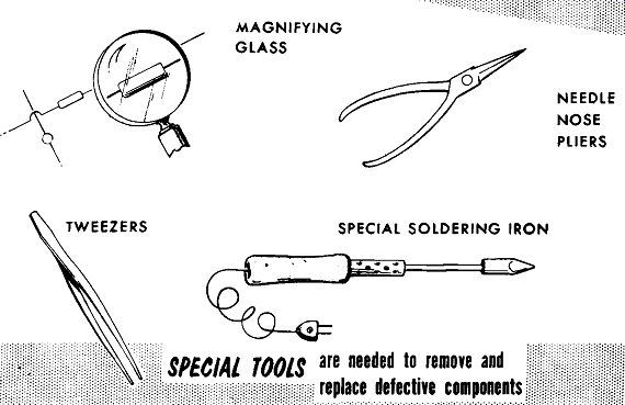
MAGNIFYING GLASS SPECIAL SOLDERING IRON
--------
The majority of transistor receivers are compact, crowded units using miniaturized components to take advantage of the small size of a transistor.
Printed circuit construction is used almost exclusively, calling for specialized techniques and tools to remove and replace defective components.
To aid in working with miniaturized components and printed circuits wiring, special tools are helpful. These include a magnifying glass, tweezers, small-size diagonal cutters, small-size needle-nose pliers, light-weight low-wattage soldering irons, special shaped soldering iron tips, etc.
Many of the special tools will be accumulated through experience in servicing transistor receivers. The components used in transistor receivers, particularly capacitors, usually have low ratings. Some capacitors are rated as low as 3 volts working voltage. This requires special precautions against testing with normal capacitor checkers that apply high voltages, and testing with ohmmeters using a battery voltage higher than the capacitor's working voltage.
Often it will be found that the trouble is other than a transistor. Barring applications of incorrect voltages due to component defects, the transistor itself will give very little trouble. More trouble may be experienced from the miniaturized components with their low ratings. Typical will be open coils, open windings in i-f transformers, leaky or shorted capacitors, capacitors with less than the rated capacity, troublesome tuning units whether inductive or capacitive, etc.
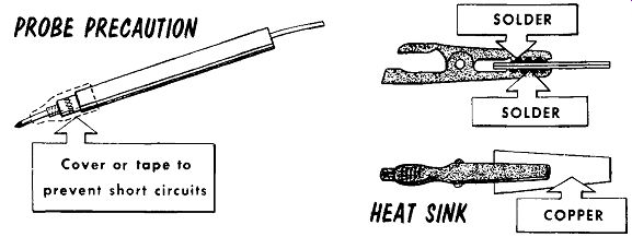
When a wired-in transistor or diode requires replacement, or testing, special care must be taken in removing the transistor from the circuit. When unsoldering the transistor leads a heat sink must be applied to the lead just above the soldering iron. A convenient heat sink is a pair of long nose pliers clamped to the lead. The pliers are also used to remove the lead as well as remove heat. There are times when using pliers as a heat sink is not advisable, or cannot be done. For such instances a heat sink may conveniently be made by soldering two pieces of copper to an alligator clip as illustrated. Clipping this to the lead for use as a heat sink will leave prevent short circuits one hand free for servicing the receiver. All of the above requirements of heat removal for unsoldering the transistor lead hold true when the lead has to be re-soldered to its terminal. When replacing transistors in push pull audio circuits, it is best when possible to replace both with a matched pair.
-----
When using the test probes of a meter, an accidental slip may cause a short circuit and/or place an excessive voltage on a transistor element. A safety precaution, see figure, is to insulate by the use of tubing, or tape, all but approximately ¼-inch of the end of the probe tip. This short length will prevent accidental short circuits, yet have sufficient bare metal to make contact with any point being measured. A sharp point on the probe is helpful where a coating of varnish or other protective insulating material is placed over the printed circuit. The increased number of electrolytic capacitors calls for an awareness of the polarity of the ohmmeter leads.
This will vary with different instrument manufacturers. The safest method is to use a separate voltmeter to determine the polarity of each of the ohm meter's test leads, and mark them carefully, either on the test lead, the test probes, or both.
Dynamic methods of servicing a transistor receiver have a lot in their favor. The use of signal tracing, or signal injection, can be helpful in quickly locating the troublesome stage. Test equipment used to service transistor receivers should have isolated transformer-type power supplies to prevent accidental application of line voltages to the transistor receiver.
If the test equipment does not use a transformer-type power supply, an isolation transformer should be used.
The signal generator, in addition to use for alignment, can be helpful in servicing transistor receivers. For signal injection be sure to use a blocking capacitor (0.01 mfd for rf, and 0.1 mfd for af). Use a low-level input signal. In some circuits the signal can be induced by clipping the generator lead to an insulated resistor, or a plastic or cardboard encased capacitor that does not have the outside foil at ground. Another method of coupling the signal is to place the generator output to a loop antenna. The signal output radiated by the loop antenna can be adjusted by either varying the space between the loop and the receiver, or by reducing the generator output.
---------
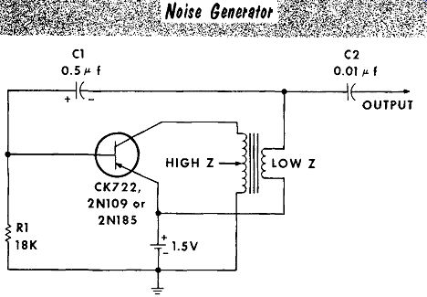
Another form of signal injection is the noise generator. The broad-band output of the noise generator can be applied either directly by a probe, or it can be radiated by a loop antenna. Preferably the noise generator should have an output amplitude control. The best use of a noise generator is for
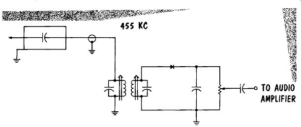
TUNED INPUT DETECTOR CIRCUIT
------------
A signal tracer can be of help in following the path of signal; however, the low impedance of a transistor circuit can create a problem in that the signal tracer can load the circuit under test. The majority of signal tracers use a diode detector, often placed in the probe, for r-f and i-f signal tracing.
A tuned circuit detector, the output of which is applied to the audio amplifier portion of the signal tracer, will reduce loading and allow tracking of r-f and i-f frequencies. Although the input of the detector is tuned to an intermediate frequency, it will also work at broadcast frequencies.
The grid-dip meter has many uses - an important one is to check the oscillator circuit. Tuning the grid-dip meter against the oscillator will indicate if the circuit is open, and/or the frequency to which the oscillator is tuned. You can also "beat" the grid-dip meter against the oscillator for a beat-frequency output signal indicated by the speaker of the receiver under test. If the receiver output stages are disabled, the beat frequency generated between the grid-dip meter and the oscillator can be heard by detecting the output of the grid-dip meter. The grid-dip meter can also be used to check the r-f and i-f tuned circuits. Another use of the grid-dip meter is as a substitute signal generator. Although the dial calibration of the grid-dip meter is not as accurate as that of a signal generator, it can be used for quick go-no-go tests. For example, if the oscillator circuit of a receiver is suspected of being inoperative, tune the receiver to local broad cast station frequency; then set the grid-dip meter to a value 455 khz higher.
The grid-dip meter acting as a substitute local oscillator will inject sufficient signal to restore operation.
Servicing Printed Circuits
Printed circuits are used in many tube-type radios, and almost exclusively in transistor radios. These circuits are laminated plastic boards with a thin sheet of copper foil bonded to one side. By various photographic and etching processes, some of the foil is removed leaving thin ribbons of foil to act as conductors. Where components are mounted, holes are punched in the board with the copper foil encircling the hole. The component lead is then inserted through the hole and soldered to the copper foil. Wire leads are soldered while the wire is going straight through the hole, and lugs or tabs are bent over and soldered to the foil. The soldering is done all at once by dipping the completed board deep enough into a pot of molten solder to solder all the lugs and wire leads. The board is then cleaned and a coating of varnish is usually applied to prevent dust and moisture from causing short circuits.
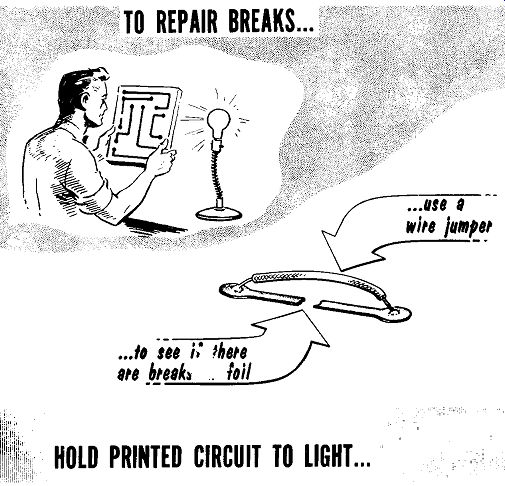
HOLD PRINTED CIRCUIT TO LIGHT ...
-----------
A fine break or an intermittent crack in the copper foil can be difficult to find, requiring the use of a magnifying glass. Small breaks in the copper foil can be repaired by cleaning the insulating varnish from the printed conductor at either side of the break, and placing a jumper of solder across the break. A large break in the foil can be repaired by jumping the open section with a wire soldered at each end as shown.
The printed circuit board, when removed from the radio case, should be handled with care, as it is easily cracked and broken. When soldering a lead, the soldering iron should not be applied for too long a period to pre vent overheating and breaking the copper foil. The soldering iron should be of small size, approximately 35 watts dissipation. When soldering be careful not to let any blobs of solder fall on the board and cause a short circuit.
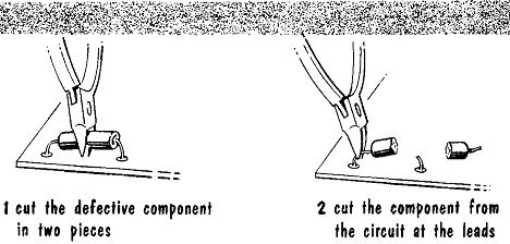
1. cut the defective component in two pieces; 2. cut the component from the circuit at the leads
--------
When changing a defective component with short leads, cut the component in half with diagonal cutters, see figure. After the component is cut in half, each half should be cut by the diagonal pliers until the end of the lead inside the component is reached. The ends are then cleaned and formed into a loop.
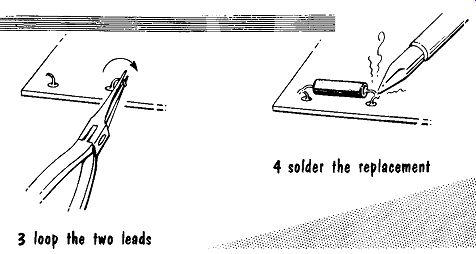
3. loop the two leads; 4. solder the replacement
---------
The leads of the replacement component are then formed into a loop and entwined about the loops of wire formed from the leads of the old component as illustrated. The loops are crimped together and soldered.
The soldering iron used for removal of components should be of a higher wattage than that used to solder components to the printed circuit. More heat is required for clean "unsoldering". A typical value would be a 60-watt iron or a soldering gun.
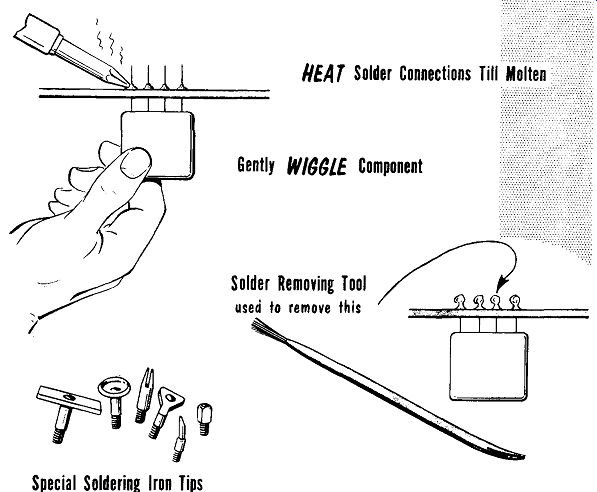
To remove components mounted with multiple lugs running straight through holes in the board, the soldering iron is applied to one lug. When the solder becomes molten the component is wiggled back and forth while the iron is removed. The continuous wiggling prevents the solder from adhering and will result in a broken connection after the solder has cooled.
Repeating this process with the remaining lugs will permit removal of the defective component.
Special Soldering Iron Tips
Gently WIGGLE Component
Solder Removing Tool -- used to remove this
-------
Components held in place with bent-over lugs require a different method of removal. One type of soldering aid available has a stainless-steel wire brush at one end and a pointed or slotted probe at the other end. Applying the soldering iron to the bent-over lug will cause the solder to melt; the molten solder is then carefully brushed off the lug and copper foil by the stainless steel brush. After the solder is removed the probe end is used to straighten the bent-over lug. With the lug straight the connection can be broken by wiggling the component with the soldering iron applied as previously mentioned. Various special-shaped soldering-iron tips designed for removing printed circuit components are also available.
Printed Circuit Component Testing
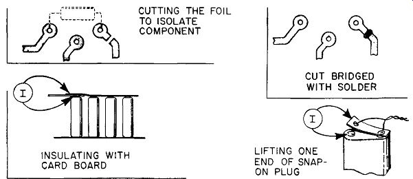
In testing components mounted on printed circuit boards, we often have to lift one end to be sure the component being tested is not being paralleled by another component. In printed circuits lifting one end to isolate a component creates a problem, such as unsoldering bent-over lugs of a control or i-f transformer. The possibility that the work may be needless and only lead to damaging the component or the board, further aggravates the situation. A quick way out is to carefully cut the printed circuit lead to the end of the component. The cut should be made carefully with a sharp penknife blade, or a pocket-type razor knife. Depending upon the type of board, a straight cut may provide sufficient separation. If necessary two close cuts may be made with a narrow strip of foil lifted to make a clean separation. After checking the component, carefully clean the foil on both sides of the break and fill the gap with solder. For testing or substituting transistors, or other multiple-lead devices, cut all but one of the leads.
INSULATING WITH CARD BOARD CUTTING THE FOIL TO ISOLATE COMPONENT CUT BRIDGED WITH SOLDER LIFTING ONE END OF SNAP ON PLUG
--------
Transistors are current-operated devices. As such, current readings are often more meaningful than voltage readings. To take current readings brings up the same problem mentioned above -- the problem of Jilting one end of a circuit to allow insertion of a current reading meter. This problem is solved by cutting the printed circuit lead as previously mentioned. Depending upon the type of receiver, there are various methods of measuring the entire receiver-current drain. For receivers using a series of cells for a power source, the end cell can be insulated from the cell holder contact by a piece of cardboard or paper. Placing the current meter on either side of the insulator will close the circuit and provide a meter reading. For receivers using a battery and snap-on plug, snap on only one end of the plug, and then place the current meter between the battery terminal and the free end of the plug. In all cases, carefully set the polarity of the meter leads to prevent pegging the meter needle backwards. Typical receiver-current values for small pocket portables are between 5 to 15 milli amperes, with larger multi-band portables draining from 10 to 25 milli amperes from the source. These readings should be taken with the receiver tuned off-station for no-signal operation.
Single-Ended Audio Power Output Stage
A preliminary word of caution when handling power transistors used for audio power output circuits: Be sure to check if insulating washers are used between the chassis and the transistor. When insulating washers are used, be very careful to replace them when removing and replacing the power transistor.
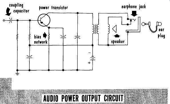
A typical single-ended, class A power amplifier is shown. Operating class A, collector current will flow constantly, requiring a heat sink to insure the dissipation of the heat developed by the current.
coupling l capacitor power transistor
-----------
For a distorted signal output, check for a defective speaker with the voice coil rubbing against the pole piece. A defective transformer having shorted turns will cause a mismatch. Incorrect bias voltages on the emitter or base of the transistor will also cause distortion. Be sure to remove the transistor before testing the output transformer or any of the voltage-divider or bias resistors. Check the coupling capacitor and the capacitor across the output transformer primary for excess leakage resistance.
The earphone jack is a normally-closed type. That is, when the ear plug is not plugged in, the contacts are closed, permitting the loudspeaker to operate. Conversely, when the ear plug is inserted, the contacts are separated; only the ear plug is connected to the secondary of the transformer.
If the spring contact should become loose, intermittent operation of the receiver may result.
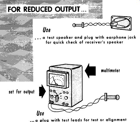
Reduced output can be caused by the same difficulties that cause distortion.
A defective output transformer with shorted turns will cause reduced out put. Check for correct bias voltages at the emitter and base of the transistor.
Remember to remove the transistor before testing the output transformer or any resistors. Check the coupling capacitor for reduced capacity.
--set for output
a test speaker and plug with earphone jack for quick check of receiver's speaker multimeter the
---------
For no output, check the earphone jack for a closed circuit from the output transformer through the speaker voice coil. Check the speaker for an open speaker-voice-coil winding. On rare occasions a receiver used at a beach may have grains of sand "freezing" the voice coil in the speaker pole piece.
Another check is for correct bias voltages. Check for a defective transistor.
The absence of collector voltage could be due to an open primary winding in the output transformer, or a shorted capacitor across the primary winding of the output transformer. Check the base bias voltage; if incorrect check the values of the resistor voltage divider, and for a leaky coupling capacitor. Check emitter bias voltage; if too high look for a defective transistor or open bypass capacitor. Too low an emitter bias can be a defective transistor or a change in value of the bias resistor. Low emitter bias can also be a result of low collector voltage. Be sure to remove the transistor before making ohmmeter checks.
Push-Pull Audio Power Output Stage
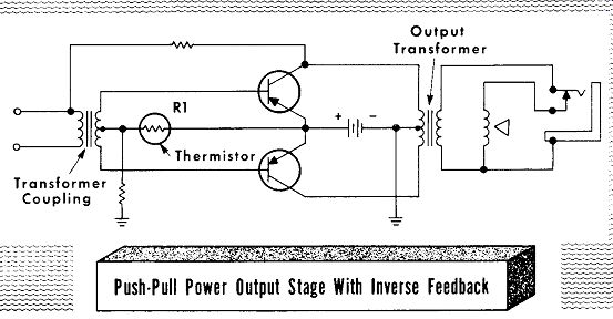
A typical push-pull power-output stage uses transformer coupling to accomplish phase inversion and an output transformer to match the push-pull transistor impedance to the speaker impedance. Usually this stage is operated class AB, with the transistors biased close to but not quite at cutoff. To prevent thermal runaway and maintain a constant bias, thermistor R1 is used in the bias circuit. A reminder: before making any ohmmeter checks of circuit components, be sure to remove the transistor.
For a distorted output, check for a defective speaker with the voice coil rubbing against the pole piece. A defective input or output transformer having shorted turns will cause a mismatch, or an open feedback resistor may cause distortion. Incorrect bias voltages may be due to a defective thermistor, or a change in resistance value.
Output Transformer
Thermistor
Push-Pull Power Output Stage With Inverse Feedback
----
Reduced output can be caused by many of the same difficulties that cause distortion. A change in the feedback resistor value could provide excessive feedback. Shorted turns in the input or output transformer will cause reduced output; incorrect base bias voltage due to a change in value of the bias voltage divider network can also cause reduced output.
For no output, check the earphone jack for a complete circuit from the output transformer secondary to the speaker voice coil. Check for an open speaker-voice-coil winding. If the receiver has been used at a beach, grains of sand may "freeze" the voice coil in the speaker pole piece. Check the collector voltage; if no voltage is present, check for an open primary winding in the output transformer. Check the base bias voltage; if no voltage is present, check for an open secondary winding in the input transformer, or an open resistor or thermistor in the bias voltage-divider network. The previous checks have tested all but the primary winding of the input transformer. If open it would cause loss of output. This can be checked by reading the collector voltage of the audio amplifier transistor driving the input transformer.
Audio Driver or Audio Amplifier Stage
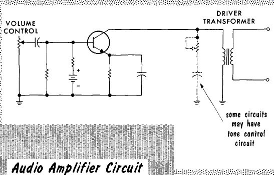
A typical audio amplifier or audio driver stage amplifies the signal developed across the detector load (volume control), and applies it to drive the audio power-output stage.
VOLUME TRANSFORMER; CONTROL
es -= some circuits may have tone control circuit
----
For distortion, or reduced output check the base bias; if incorrect, check the bias voltage-divider network. A reduced-value coupling capacitor will reduce the input signal, causing distortion. Check the emitter bias; if incorrect check the emitter resistor and bypass capacitor. An open emitter bypass-capacitor may also cause low output or distortion. Shorted turns in the primary of the driver transformer or a shorted tone-control capacitor may be a source of low volume or distortion.
With no output, check the collector voltage; too high a collector voltage may be the result of a defective transistor. Circuits using an n-p-n transistor may have too low a collector voltage as the result of a defective transistor.
The absence of collector voltage may be due to an open primary winding in the driver transformer. The earphone jack, because of sufficient output of the audio driver, may often be found in the driver circuit. If so, the jack should be checked for an open circuit. Check the base bias; if the wrong value of voltage, or no voltage is present, check the bias voltage-divider network. Test for an open coupling capacitor.
SUMMARY
Most transistor receivers are compact, crowded units, using miniaturized components on printed circuit boards.
Special tools are used to repair and remove miniaturized components from printed circuits.
Transistors do not give much trouble, but most of the difficulties will be from the miniaturized components with their low ratings.
When removing or inserting a diode or transistor, use a heat sink.
To prevent accidental slips on a crowded printed circuit board, tape over the test probes exposing about 1/8-inch of bare metal.
To prevent accidental application of line voltages to the receiver, operate all test equipment with transformer isolated power supplies.
A popular method of coupling the signal generator output to a receiver is to place the generator output to a loop antenna and then place this loop antenna close to that of the receiver.
A broad-band noise generator helps to quickly isolate a defective stage.
A signal tracer using a tuned input reduces circuit loading and allows tracking of r-f and i-f frequencies.
Breaks in the copper foil conductors can be bridged by jumpers of solder for small breaks, and wire jumpers for large breaks.
The soldering iron used for removal of components should be of a higher wattage to permit clean "unsoldering." To take readings of the battery current drain, isolate a cell from its holder by using a piece of cardboard. For receivers using a battery plug, only one end need be snapped on, leaving the other end free for series insertion of the current meter.
When working with power transistors be sure to check if insulating washers are used between the transistor and chassis.
Thermistors may be used in the base to emitter bias circuit to prevent thermal runaway.
REVIEW QUESTIONS
1. Name some of the specialized tools that help in servicing miniaturized components on printed circuit boards.
2. What tool constitutes a convenient heat sink for use in inserting or removing a diode or transistor?
3. What precaution should be followed when replacing a transistor in a push-pull amplifier?
4. Why is it helpful in servicing printed circuits to have a sharp point on the meter probe tip?
5. Describe one method for determining the polarity of the test leads of an ohmmeter.
6. Describe some of the uses of the grid-dip meter as a test instrument for transistor receiver servicing.
7. What is the purpose of the coating of varnish usually applied to printed circuit boards?
8. What precautions must be taken when handling power transistors?
9. What qualities of a thermistor help prevent thermal runaway?
+++++++++++++++++++
Power Detector and AVC Stage
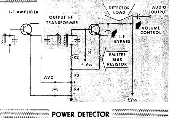
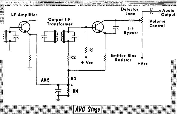
A power detector provides both detection and amplification. By biasing the transistor at or near cutoff, one-half the modulated input signal is rectified. The amplified output at the collector has the r-f element bypassed to provide the detected-amplified, audio output signal. Varying the arm of the volume control varies the total series value of the collector load, which consists of the load resistor in series with a portion of the volume control. Varying the value of the collector load will vary the value of the detector output signal. The base bias is developed by a voltage divider …
I-F AMPLIFIER OUTPUT I-F TRANSFORMER AVC
-----
… consisting of R1, R2, R3, and R4, with R4 bypassed to provide a steady d-c output which is used as the A VC voltage. Application of an input signal to the base will have the negative-going portion cut-off by the base bias, and the positive-going portion of the signal voltage will add to the bias voltage across R2, R3, and R4. The signal-developed increase in positive voltage across R4 is filtered and fed back to the emitter of the i-f amplifier as the AVC voltage.
To check for oscillations causing howling and squealing, look for an open AVC bypass capacitor allowing positive feedback to the i-f amplifier stage.
An open i-f bypass capacitor in the collector-to-emitter circuit could also be the cause of oscillations. Should the i-f bypass capacitor require replacing, be careful to place it in the same position as the original capacitor. Placed incorrectly it could cause feedback between the output and the input of the stage causing oscillations.
Reduced output or distortion can be the result of a defective transistor or a defective A VC or i-f bypass capacitor. Check for a defective winding of the output i-f transformer. Check the base and emitter bias voltages; if there are any discrepancies check the voltage-divider network. Distortion …
Load I-F Bypass Emitter Bias Resistor
+Vee
~Audio Output Volume Control
---------
… or reduced output could also be caused by a change in the value of the detector load in the collector circuit, or a change in value of the coupling capacitor in the output circuit. If there is a marked change in the value of either R2, R3, or R4, it may cause the distortion, and, naturally, the defective component should be replaced. In some extreme cases, a defective transistor may be the cause of distortion. Care should be taken when making the component change that no other components are damaged during the replacement. A low-wattage iron should be used on the transistor leads if they are to be soldered.
Loss of output can be caused by a defective transistor, an open winding in the output i-f transformer, or a shorted i-f bypass capacitor. An open, collector load resistor or an open connection at the wiper arm of the volume control could also cause loss of signal. Check for an improper value of base and or emitter bias voltage: if there are any discrepancies in the values, check the voltage-divider network. An open coupling capacitor can also cause the loss of the output signal. For loss of the collector voltage, check the collector load resistor and the volume control. For printed-circuit boards, check the connecting lugs of the volume control to be sure they are well soldered to the printed-circuit terminals.
Diode Detector and AVC Stage
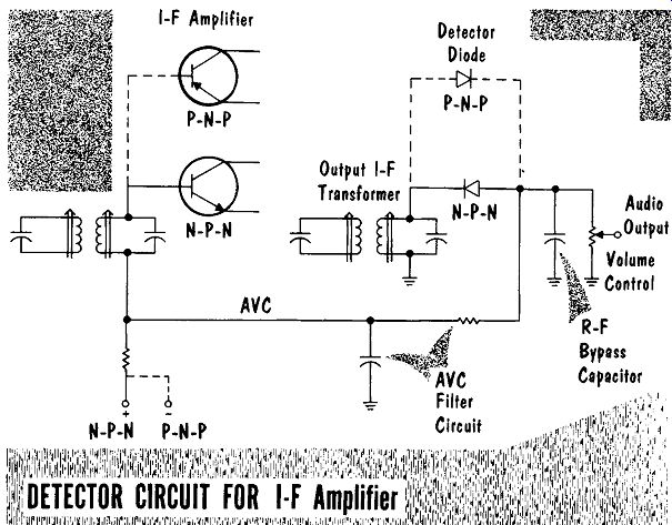
The diode detector stage is also the source of the AVC voltage used to control the gain of one or more i-f amplifier stages. The polarity of the detector diode output is determined by the polarity of the AVC bias voltage required at the i-f amplifier, which in turn is determined by whether the i-f amplifier is an n-p-n or p-n-p transistor.
Oscillation (howling and squealing) can be caused by an open A VC bypass capacitor allowing positive feedback of the detected signal. Another cause could be an open r-f bypass capacitor across the volume control in the detector circuit.
I-F Amplifier i---cr I I P-N-P AVC
0 Detector Diode r--- ---7 P-N-P
------------
Reduced or distorted output may be the result of a defective diode, an open or reduced-value AVC bypass capacitor, or an open or reduced-value r-f bypass capacitor. A defective winding of the output i-f transformer may also cause reduced output or distortion.
With no output, check for a defective diode, an open winding in the output i-f transformer or a shorted r-f bypass capacitor. For printed circuit boards, check the connecting lugs of the volume control to be sure they are well soldered to the printed circuit terminals.
I-F Amplifier Stage
Intermediate-frequency amplifiers employ high-gain, high-Q tuned circuits.
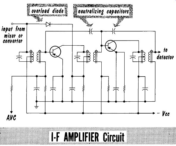
High-gain and high-Q circuits require negative feedback to prevent unwanted oscillations. This negative (degenerative) feedback is called neutralization. Another feature often found in i-f amplifier circuits is an overload diode, which prevents overloading the i-f amplifier on signals so strong that even the A VC voltage is insufficient to decrease the receiver gain.
Oscillations in i-f amplifier stages may be due to feedback. However, another possible cause in high- resistance solder connections or high-resistance ground returns. Check all solder connections for cold solder joints. To test the ground returns, use a jumper wire to parallel the ground-return lead being checked. An aged capacitor may lose some of its capacity, and become a poor bypass capacitor.
-- gain low-impedance circuits could be high input
---------------
Bridge the suspected capacitor with a good capacitor of the correct value.
Bridging suspect capacitors will also check for possible open neutralizing or bypass capacitors. A remote possibility, unless the receiver has been tampered with, is the necessity of realigning the i-f amplifier tuned circuits.
When inserting a replacement transistor in an i-f stage, check its gain; if too high it could cause oscillation.
Reduced gain and or distortion can be the result of an overload diode conducting at all times due to improper bias voltages. Distortion on strong signals could be due to an open overload diode. For wrong values of bias voltage, check voltage-divider values. Series dropping resistor values should also be checked where wrong bias values are indicated. Alignment may be off-peak, causing reduced output. When alignment of the tuned circuits indicates that it is peaking off the correct i-f value, check for shorted turns or defective capacitors in the i-f transformer. For receivers using power detectors, check the value of A VC voltage applied to the i-f stage.
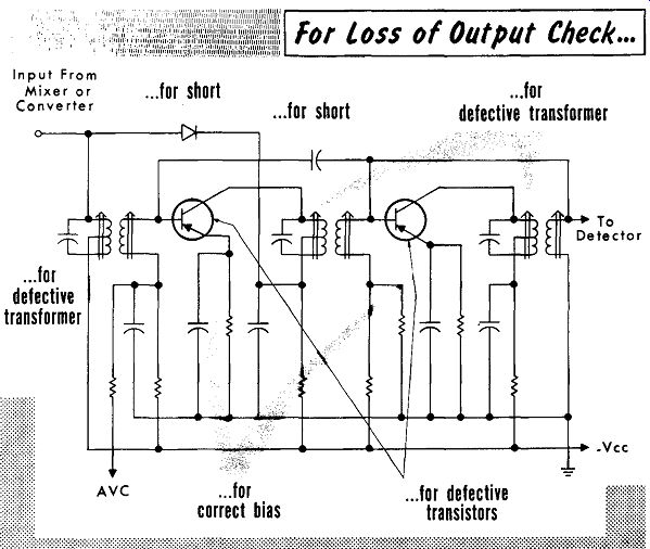
Complete loss of signal can be due to defective transistors. For defective i-f transformers, the transformer winding can be checked for continuity by voltage readings. Before making any ohmmeter check of the transformer windings, remove the transistor. For wrong values of bias voltage, check both the voltage dividers and series dropping resistors. A fused (shorted) overload diode or shorted neutralizing capacitor will also cause complete signal loss. Where transistor sockets are used, be sure that the transistor is properly seated in its socket.
Input From Mixer or Converter
... for defective transformer
... for short I for Loss of Output Check ... I
... for
... for short defective transformer
--------
Reflexed IF-AF Amplifier Stage
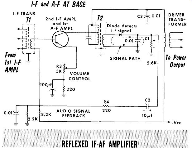
For economy the last i-f amplifier stage may double as an i-f and a-f amplifier. The collector circuit has two output leads. The i-f transformer couples the i-f signals to the detector, and the detected a-f signals are returned to the base, amplified, and then applied to the driver transformer. The i-f transformer has too low an impedance for the af to develop any signal, and capacitor C3 will bypass any i-f signals, keeping them from the driver transformer.
--------
Oscillations can be caused by open or reduced-value bypass capacitor C3, emitter bypass capacitor, or the base-bias voltage-divider bypass capacitor.
Reduced volume or distortion can also be the result of a reduced-value bypass capacitor. Check the base bias voltage; for improper values of bias voltage, check the voltage-divider values. The output i-f transformer may be off-peak and in need of alignment.
For complete loss of signal, check the detector diode and/or the i-f amplifier transistor. Check the voltage on the base for an open secondary winding in T1. Check the collector voltage for an open primary winding in T2, or an open primary winding of the driver transformer. Check with an ohm meter for an open secondary in T2.
Converter Stage
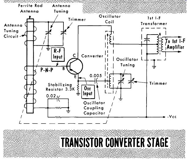
The converter stage combines the functions of the mixer and oscillator stages. Use of a single transistor results in an economy. In populous areas high-power transmitters provide a strong signal, easing the need for a stage of r-f amplification. Application of AVC voltage to the converter stage can cause variation of the oscillator's frequency, which can only be overcome by careful design. Because of its sensitivity to this problem, the majority of converter circuits do not have AVC voltage applied to it.
LOOP ANTENNA VACUUM TUBE RADIO BEING USED TO CHECK OSCILLATOR SIGNAL FROM TRANSISTOR RADIO
TRANSISTOR RADIO UNDER TEST
Another Working Receiver§ Can Be Used To Check :: Oscillator Frequency and Calibration
-----------
There are two quick checks to test the converter circuit for oscillation.
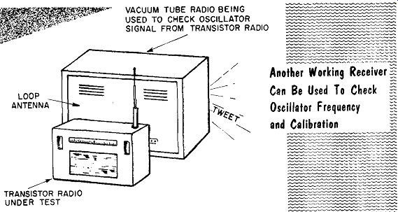
Use an operating radio receiver (tube or transistor), and set it to a local station at the upper end of the broadcast band. Set the dial of the transistor receiver under test to a setting of 455 khz lower than that of the local station, and rock the dial of the transistor receiver under test back and forth about the dial setting. If the converter circuit is oscillating, it will cause a whistle in the operating radio receiver. The whistle is a result of a hetero dyne caused by the converter oscillator producing a signal at the same frequency as the local broadcast station. This results because the transistor receiver under test has its dial set to such a value that the converter oscillator, which is tuned to 455 khz above the dial setting, is at the same frequency as the broadcast station. The two signals are beating with each other to form a "beat" frequency.
Another oscillation test of the converter circuit is to read the emitter voltage. With the meter probe on the emitter lead, the oscillator tuning capacitor can be shorted with a jumper or screwdriver, depending upon the construction of the tuning capacitor. With the rotor and stator shorted together, oscillation will cease and the emitter voltage reading should change value. When the converter oscillator is working, the emitter voltage should vary slightly as the oscillator circuit is tuned from one end of the band to the other.
Intermittent operation is more frequent in the converter stage than any other stage. As in all oscillator circuits, feedback can be critical. In this case the feedback amplifier is the converter transistor. A good transistor should be substituted for the one in question. Checking the transistor with a transistor tester may not reveal a low, alpha cut-off frequency. The oscillator coil should be carefully checked for intermittent connecting leads.
----------
Carefully check the circuit against the latest schematic diagram. Later production runs of a receiver may have different values or types of components, which is particularly true in converter circuits. Certain values, especially those of resistors setting bias voltages, or certain components, particularly coils and transistors, will be changed if the values or components used are found to be marginal.
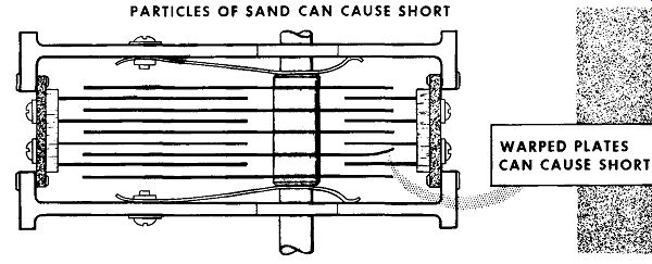
The narrow spacing between the rotor and stator plates of the tuning capacitor is a common cause of intermittent operations. Dirt or sand between the plates will cause them to warp and short.
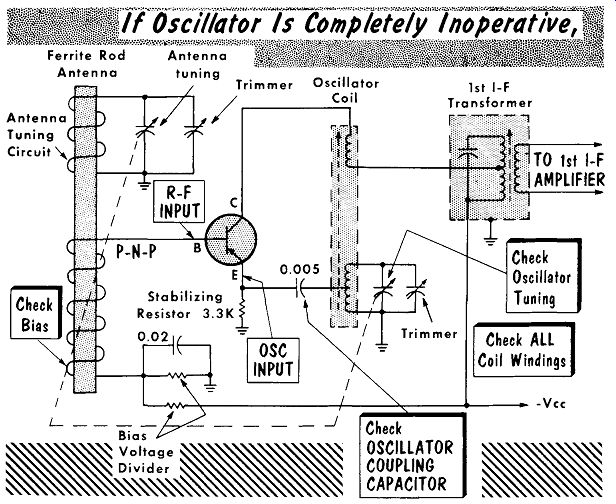
Low converter-stage gain can be a cause for a weak signal output. In addition to the possibility of a defective transistor, the alignment of the tuned circuits should be checked, particularly the alignment for oscillator tracking. Another probable cause is a defective antenna coil, or cracked antenna-coil ferrite rod.
------------
A completely-inoperative oscillator circuit will usually be indicated by incorrect bias voltages. When this occurs check the bias voltage divider, the transistor, and all coil windings. In addition to the possibility of an open oscillator-coil winding, check for an open oscillator coupling-capacitor. Be sure to remove the transistor before making any ohmmeter check of the oscillator coil or the base lead through the r-f input coil.
Compact tuning capacitors are prone to shorting between rotor and stator, either by dirt or sand, or any other reason for warping and shorting the plates.
Should all components check out good and the converter stage still is inoperative, there is the remote possibility of a defective i-f transistor loading the i-f transformer. In turn this reduces feedback through the oscillator coil to prevent oscillations.
SUMMARY
A power detector uses a transistor biased at or near cutoff to have it rectify one-half of a modulated signal while at the same time amplifying the other half of the signal.
The polarity of a detector diode is determined by the polarity of the A VC bias voltage required at the i-f amplifier, which in turn is determined by whether the i-f amplifier is an n-p-n or p-n-p transistor.
I-F amplifiers use high-gain high-Q tuned circuits requiring negative feedback to prevent unwanted oscillations.
Some i-f amplifier circuits employ an overload diode to prevent overloading of the i-f circuits on extremely strong signals.
When replacing a transistor in an i-f amplifier stage, be careful not to insert one with higher gain. Excessive gain could cause oscillations.
A reflexed i-f, a-f transistor amplifier stage is a single stage that amplifies an i-f input signal, then, after detection the audio frequency signal is fed through the same amplifier. Because of the differences in frequency there is little or no interaction.
Application of AVC voltage to a transistorized converter circuit can cause variations of the oscillator frequency. Because of this most converter circuits do not have an AVC voltage applied to it.
Intermittent operation is more frequent in the converter stage due to critical feedback paths.
Checking the transistor with a normal transistor tester may not reveal a low alpha cut-off frequency.
One quick check for oscillation in a converter circuit is to beat its output against that of another receiver. Another quick check is to monitor the emitter voltage; it should vary slightly as the oscillator is tuned from one end of the band to the other.
Component values in a converter circuit are often changed during production runs. To check this the receiver should be compared with the latest available schematic diagram.
REVIEW QUESTIONS
1. Why can't a diode be used as a power detector?
2. What is the name given to the use of negative feedback to remove oscillations in an i-f amplifier stage?
3. What is the simplest method of checking for open or reduced-capacity AVC bypass capacitors?
4. What is the advantage of an overload diode over AVC bias?
5. Describe the method used to check for cold solder joints in the ground return connections.
6. What is the main reason for using a reflexed i-f, a-f amplifier circuit?
7. When testing the local oscillator by beating it against that of another receiver set to 1050 khz what should the dial setting be for the receiver under test?
8. Shorting the stator and rotor of the tuning capacitor causes a change in the voltage of what element of the converter transistor?
Local Oscillator-Mixer Stage
-----------
The more costly multiband and AM-FM receivers will, for the most part, use a separate local oscillator and mixer stage. Higher gain, application of A VC to the mixer, plus the improved stability of a separate oscillator are the major advantages.
As in the converter stage, a quick check of the oscillator is to use an operating receiver: set it to a local station at the upper end of the broadcast band, and set the dial of the transistor receiver under test to a setting 455 khz lower than that of the local radio station. Rock the dial of the transistor receiver under test back and forth about the dial setting. If the converter circuit is oscillating, it will cause a beat note whistle in the operating receiver.
Another quick check for oscillations is a reading of the emitter voltage.
With a meter probe on the emitter lead, short the rotor and stator plates of the tuning capacitor either by a jumper or a screwdriver. Shorting the tuning capacitor will stop oscillations and change the meter reading. When the oscillator is operating, the emitter voltage will vary slightly as the oscillator circuit is tuned from one end of the band to the other.
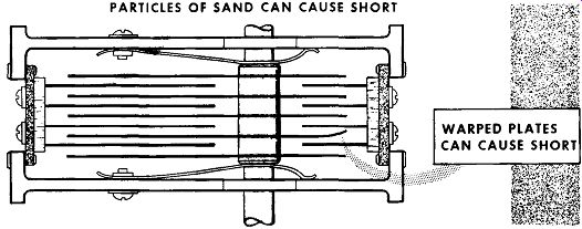
For intermittent operation of the oscillator, the first check should be of the transistor. Checking it in a transistor tester may not reveal a low, alpha cut-off frequency; it is best to replace with a good substitute. Check the oscillator coil for any intermittent connecting leads. Look for dirt or sand between the rotor and stator of the tuning capacitor, or for any warping causing the tuning capacitor to short. Check the circuit against the latest schematic diagram, looking for different values or types of components. Any marginal values or types of components may be changed in a later production run.
Although it will not have as pronounced an effect as in a converter stage, misalignment of the local oscillator can cause a reduced output to the mixer.
Decoupling resistors, particularly the resistor in the -V cc lead to the oscillator collector, should be checked for excessive voltage drop causing a reduction in the oscillator output. Reduced oscillator output can also be a result of a change in value in the feedback capacitor from the oscillator coil to the emitter, or a defective mixer stage loading the oscillator emitter circuit.
An inoperative oscillator will often be indicated by incorrect bias voltages.
PARTICLES OF SAND CAN CAUSE SHORT
-------
Before checking bias circuits with an ohmmeter, be sure to remove the transistor. Check the bias network, being sure to check the capacitor be-ween base and ground. Check the oscillator coil windings for continuity and check for a shorted C1, the coupling capacitor between the oscillator and mixer.
To check the mixer stage for low output, with the oscillator known to be working, check the bias voltages, particularly the A VC bias voltage. Check for misalignment of the i-f transformer at the output, or the r-f transformer at the input to the mixer. For an inoperative mixer check the transistor, and check for an open oscillator coupling capacitor, C1. The primary of the i-f transformer can be checked to the impedance matching tap by measuring the collector voltage. To test for continuity in the remainder of the winding, an ohmmeter is used after removal of the transistor. Check the secondary of the r-f transformer by reading the value of base bias voltage.
R-F Amplifier Stage
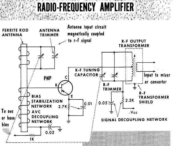
Multiband receivers, or AM-FM receivers will often contain a stage of r-f amplification. Operating at higher frequencies, the r-f amplifier stage re quires a transistor with a high alpha cut-off frequency. In addition to increased gain and selectivity, a stage of r-f amplification will reduce the overall noise level on weak signals, and is an aid in elimination of image frequency response. The r-f amplifier stage usually operates with A VC bias, enabling the receiver to handle strong signals that could normally cause overloading and distortion.
-----
Any noise generated in the r-f amplifier, the first stage in the receiver, will be disproportionately loud at the output. Therefore, any rubbing, or dirt between the stator and rotor of the tuning capacitor will be quickly apparent as the receiver is tuned throughout the band. In multiband receivers, the bandswitch can also cause a high noise level when changing bands. To clean a noisy bandswitch, use a conducting lubricant such as the type used for television tuners. A noisy transistor is another possibility that should be checked by replacing with a substitute.
The high-gain high-Q circuits used in the r-f amplifier are prone to break into undesired oscillations, particularly when the decoupling capacitors open or lose capacity. In circuits using neutralization, check for an open feedback capacitor.
For low gain check the alignment of the antenna and r-f trimmers. Check for an open antenna coil or a possible break in the antenna ferrite rod. An incorrect value of base and/or emitter bias can also cause reduced gain.
Check for an open, emitter bypass capacitor. Another possible cause is an incorrect A VC bias voltage, reducing the stage gain.
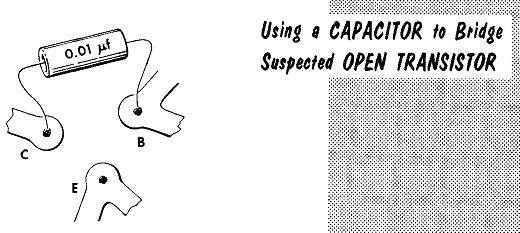
For an open r-f stage, if the transistor is suspected of being inoperative, a quick check is to remove the transistor and apply a 0.01-mfd capacitor from the base to collector socket terminals. This will couple the signal to the mixer stage. The receiver gain and sensitivity will be reduced; how ever, this test will quickly indicate an open transistor. In multiband receivers a defective band switch may allow operation on one band but not an other. This may also be the result of an open coil or coil lead in either the antenna or r-f tuned circuits. Check for dirt, sand, or any other cause for warped plates resulting in a short in the r-f or antenna tuning capacitor section. Sometimes a piece of solder that has become dislodged may manage to stick in the capacitor plates, and short the aforementioned circuits.
In removing the obstacles, care should be taken that the plates are not bent. Bent or warped plates, although not shorting out the tank circuits, may introduce tracking error. An excellent method for reaching hard-to-get places is to use a vacuum cleaner. Shaking the receiver may not always work, and may even loosen a soldered connection which will give trouble later. Check all bias voltages, particularly the A VC bias values.
---------
Hybrid Auto Receiver
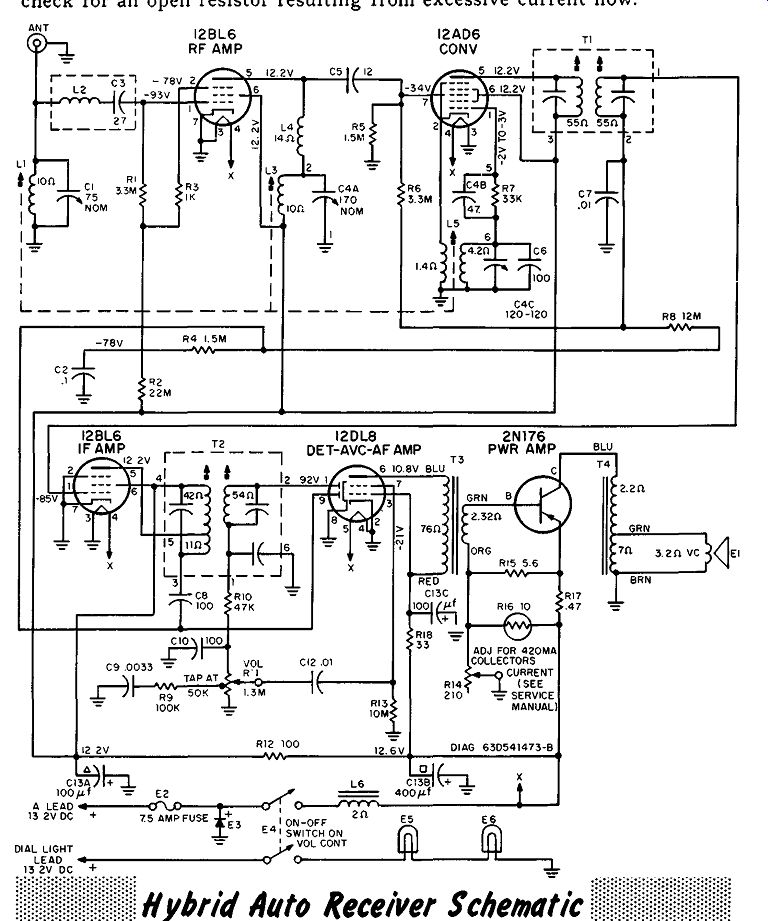
Many methods have been devised to overcome the maintenance problem of auto-radio-vibrator power supplies. One of these employs specially designed vacuum tubes using 12 volts for filament, screen, and plate voltage.
These tubes perform satisfactorily as voltage amplifiers, but they are not suitable for power amplification. Power output transistors are used to over come this problem. The transistors are mounted on the outside of the metal cabinet enclosing the receiver, thus using the entire cabinet as a heat sink.
This combination of tube and transistor creates a "hybrid" radio receiver.
Aside from the 12-volt filament, plate, and screen voltage, the greater portion of the receiver circuit is conventional. The differences are that the cathodes of the r-f and i-f amplifiers are placed directly at ground for maximum gain. Impedance coupling is used between the r-f amplifier and converter for maximum gain. The grid closest to the cathode of the 12DL8, detector-audio amplifier, is not the control grid but an "accelerator" grid having a 10-volt positive potential applied to it. The accelerator grid's positive potential, and its location next to the cathode will cause it to pull a large number of electrons from the cathode to increase plate current. This increased plate current is conventionally controlled by ·the control grid, pin 7, of the tube. As is common in many auto radios, a low frequency of 262.5 khz is used as the i-f. The full value, A VC bias voltage is applied to the i-f amplifier, with a reduced value applied to the r-f amplifier to provide higher gain in the r-f amplifier circuit.
In the transistor output circuit, a rheostat in series with a thermistor forms a variable voltage divider. The rheostat is used to reset the base bias when replacing the output transistor (bias must always be set with the speaker and output auto transformer connected). The thermistor prevents thermal runaway and helps maintain a steady base bias under varying temperature conditions. Because of the high collector current (about 1 ampere), the emitter resistor has a very low value of 0.47 ohm. Very high values of electrolytic filter capacitors are required because of the low impedance of the output transistor.
A word of caution: be sure the speaker and output (auto) transformer are always connected in the circuit before turning the receiver on or making any checks.
For distortion and/or reduced output, check for a warped, speaker voice coil rubbing on the pole piece. Check for incorrect bias voltages, being sure to check the collector current value set by the rheostat. Check the thermistor value with an ohmmeter. Another possibility is shorted turns in the output (auto) transformer.
Loss of output can be the result of a defective transistor; check carefully for a short between collector and emitter. It can also be a result of the speaker plug being out of its socket, or an open speaker voice coil. An open output (auto) transformer winding is checked by the presence of collector voltage - normally zero voltage. Some receivers use a special interlock switch or plug which will open the collector circuit by removing the speaker. Check this interlock for an open circuit. Check for a shorted insulating washer between the transistor and the receiver case, or, when a separate heat sink is used, check for a short between the insulated heat sink and the metal case. The emitter resistor acts as a fusible resistor; check for an open resistor resulting from excessive current flow.
--------
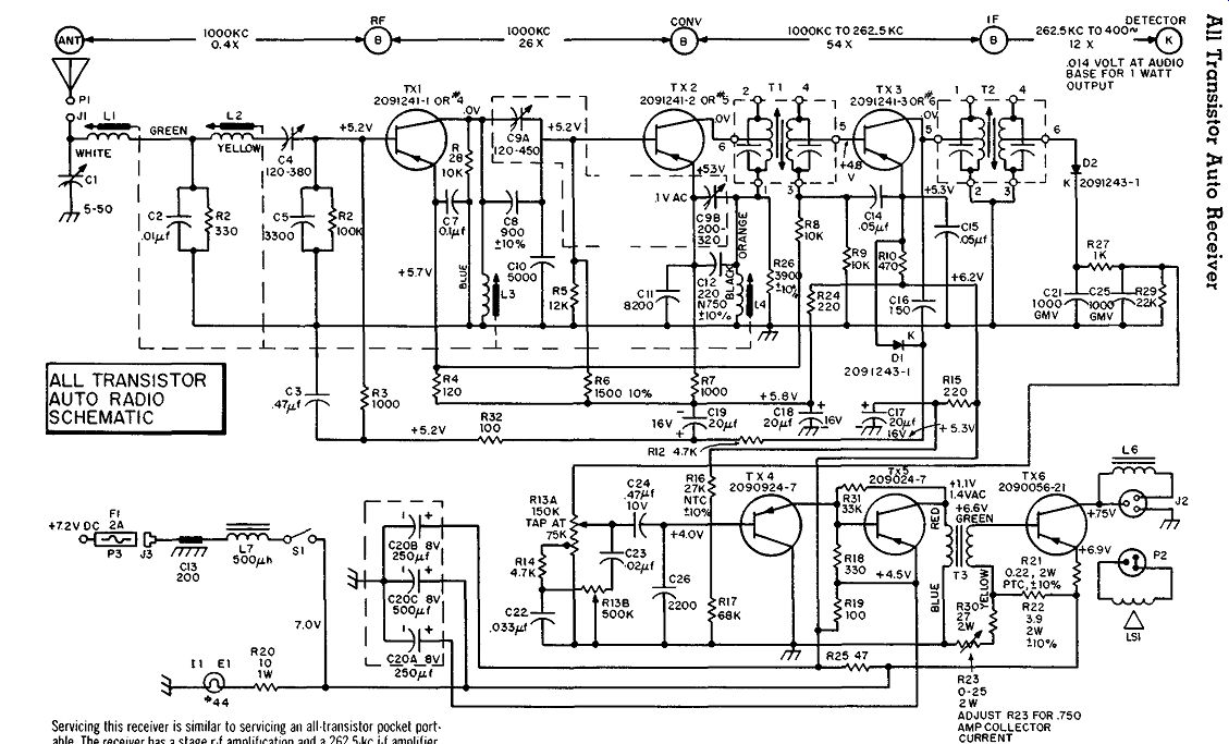
-------- Servicing this receiver is similar to servicing an all-transistor
pocket port able. The receiver has a stage r-f ampliflcat1on and a 262.5 -khz
i-f amplifier.
A diode detector is followed by two direct-coupled stage of audio amplification, and transformer-coupled to a single-ended power-output stage.
AVC bias is developed by a separate rectifier HI the i-f amplifier stage.
SUMMARY
Multiband and AM-FM transistor receivers most often use separate local oscillator and mixer stages.
Transistors used in oscillator circuits should be checked by a known good substitute.
Although not as pronounced as in a converter stage, misalignment of the local oscillator can cause a reduction in mixer output.
Multiband and AM-FM receivers often contain a stage of r-f amplification.
A stage of r-f amplification reduces overall noise level on weak signals and aids in eliminating image frequency response.
The r-f amplifier stage usually operates with A VC bias.
Noise generated in the r-f amplifier, the first stage in the receiver, will be disproportionately loud at the output.
The high-gain high-Q circuits of the r-f amplifier easily break into oscillations.
To check a suspected open transistor in the r-f amplifier stage, a 0.01 microfarad capacitor can be placed from base to collector terminals to couple the signal to the mixer stage.
Aside from the 12-volt filament, low screen and plate voltages, the tube circuits of a "hybrid" auto radio are for the most part conventional.
For maximum gain the cathodes are placed directly at ground.
The 12DL8 detector-audio amplifier uses an "accelerator" grid between the control grid and cathode. The accelerator grid is used to pull large numbers of electrons from the cathode.
A rheostat is often used to reset the base bias when changing power output transistors.
Because of the high collector current (about one ampere), the emitter resistor has a very low value of 0.47 ohm. This resistor can also act as a fuse, opening when excessive emitter current flows.
Some receivers use a special interlock switch or plug that opens the collector circuit if the speaker is removed.
REVIEW QUESTIONS
1. What are the three major advantages of using a separate local oscillator and mixer stage?
2. What effect does a stage of r-f amplification have on a receiver's gain and selectivity?
3. What do we call the inverse feedback used to prevent oscillation in some r-f amplifier circuits?
4. Describe one method of checking a bandswitch on a multiband receiver.
5. Why is no power supply required for a "hybrid" auto radio?
6. Why :1re the audio power output transistors mounted on the outside of the receiver cabinet?
7. Why is impedance coupling used between the r-f amplifier and converter of the "hybrid" auto receiver?
8. What is the purpose of the thermistor in the audio power output transistor circuit?
9. Why must bias always be adjusted with the speaker and output auto transformer connected?
+++++++++++++++++++++++++++++
General Symptoms
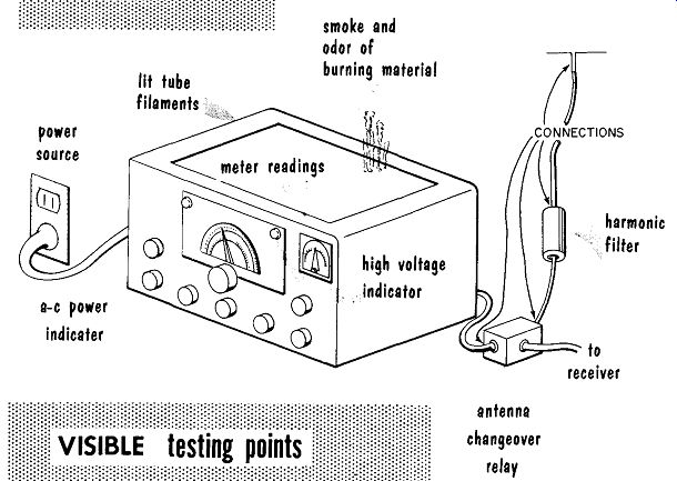
Repairing a defective transmitter requires the same reasoning and logic applied to repairing a defective receiver. When faced with a defective transmitter, we do not grab a soldering iron and diagonal cutters and dig in, but we try to reason the difficulty by observing with three of our senses all that can be seen, heard, and, where applicable, smelled. An obvious first step, but too often overlooked because it is obvious, is to check the presence of a-c power to the transmitter. This test includes checking that a-c power is available at the outlet, and that it is being applied to the transmitter power supply as indicated by a pilot light or other form of power indicator.
This first step should include observing all power supply fuses.
Power source; a-c power indicator; lit tube filaments; smoke and odor of burning material;
CONNECTIONS; harmonic filter; to receiver antenna changeover relay.
--------
A visible test should be made for the on-or-off presence of pilot-light or dial-light indicators, for lit tube filaments, overheated tube plates, smoke, and charred components. Another obvious, but often overlooked, problem is an improperly set or accidentally moved dial knob, and/or switch set tings. Meter readings should be taken and compared to the correct readings obtained during normal transmitter operation. A visible check should also be made of the various connections used to couple the microphone to the input amplifier, the transmitting key to the keying jack, the operating voltage to the antenna changeover relay, the r-f output of the transmitter, the connectors at the input and output of a harmonic filter (where used), the input and output of the antenna changeover relay, and the connector or connection of the transmission line to the antenna.
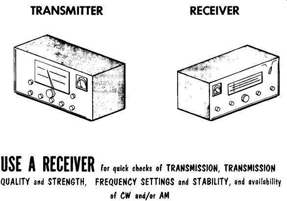
Audible tests can be made for any possible arcing, particularly in the final amplifier stage. Relays can be checked by listening for their "pull-in" or "drop-out" noise as they are controlled. A test receiver can be tuned in to the operating frequency and used to check for transmission of a signal, the signal strength, and for a distorted signal.
TRANSMITTER RECEIVER USE A RECEIVER for quick checks of TRANSMISSION, TRANSMISSION QUALITY and STRENGTH, FREQUENCY SETTINGS and STABILITY, and availability of CW and/or AM
------
The sense of smell can be used to determine if any components are over heating.
Other checks can be made by determining if the problem is on one particular band of frequencies or on all bands. For AM-CW transmitters, tests can be made to determine if the transmitter is defective on either CW, or AM, or both. Meter readings may indicate that the transmitter is tuning correctly up to the final amplifier, but the final cannot be tuned. This would call for a check of the transmission line or any device in the transmission line such as harmonic filters, changeover relays, and, at the end of the trans mission lines, the antenna. Some transmitters use control circuits allowing operation from a remote or central operating position, which must be checked for possible defects.
Meter Readings
Metering is required not only for tuning a transmitter, but also for monitoring it. If not already listed in the instruction manual of the transmitter, it would be wise to list all normal-operating meter readings when the transmitter is operating properly. These readings serve as a valuable means of comparison when troubleshooting a defective transmitter.
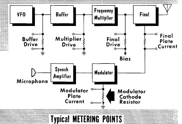
VFO Microphone Frequency Buffer Multiplier Final Drive Bias Speech Modulator Amplifier Modulator Plate Current 0
Modulator Cathode Resistor Final Plate Current
----
A low power transmitter and its typical metering circuits is shown in the block diagram. Meter readings can be taken in either of two manners: from the oscillator output to the final, or from the final back to the oscillator output. For this discussion we will start with the oscillator. It should supply sufficient drive to the buffer stage over the entire tuning range.
If there is insufficient drive, check to see if the oscillator is defective on all bands or on one band alone. Many transmitters are designed to be able to switch the oscillator, or the buffer stage following the oscillator, to act as a crystal oscillator. Where this feature is available, and the oscillator drive is low or absent, a crystal should be inserted in the crystal holder and the switching circuits set to use the crystal oscillator. In transmitters using the buffer as a crystal oscillator-in which the use of a crystal restores the drive-the restoration would be indicated by the presence of a driving signal at the input to the frequency multiplier. In transmitters using the oscillator tube as a crystal oscillator-in which the use of a crystal restores the oscillator output-the restoration would be indicated by the presence of a driving signal at the input to the buffer.
The buffer stage is often fixed-tuned and has no tuning adjustments. Its proper operation can be checked by the presence of a driving signal at the input to the frequency multiplier stage. In buffer circuits using tuning adjustments, these adjustments are set for a maximum input signal to the frequency multiplier. A meter reading of sufficient input to the buffer, and a meter reading showing no input or insufficient input to the frequency multiplier, indicates a defect in the buffer stage. These meter readings should be checked on all bands.
----
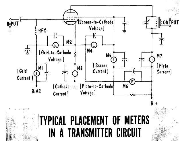
TYPICAL PLACEMENT OF METERS I IN A TRANSMITTER CIRCUIT
The frequency multiplier stage is checked in the same manner as the buffer stage. When operating properly it should provide sufficient drive to the final stage. As the bands are changed, or the frequency within a band is changed, the frequency multiplier should be retuned for maximum output to the final stage. A meter reading of sufficient input to the frequency multiplier, and a meter reading of no input or insufficient input to the final stage, indicates that the defect is in the frequency multiplier stage. The meter readings should be checked on all bands. Typical placement of meters in a transmitter circuit is shown in the illustration.
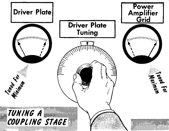
The final amplifier has a metered input indication of the drive in the grid circuit; its output indicator is the plate-current meter setting. With the proper amount of drive to the input of the final, the output circuits should be tuned for the correct plate current as determined by the type of power amplifier tube used. Any reduction in drive will result in an increase in the plate current reading. With sufficient drive to the input, but with a severe dip in the output tuning that results in a low level of plate current, check for loss of the output load. This could be either a disconnected trans mission line or antenna. To check, place a dummy load on the output connector and retune the output. If the plate current reading returns to normal, the difficulty is with the transmission line or antenna. If the reading remains low, the difficulty is within the final stage.
For AM transmission, a quick check of speech amplifier and modulator circuits is to observe the cathode current readings of the modulator. The meter should read the correct current value and should deflect back-and forth in step with any speech input to the microphone. The plate-current meter reading of the final should also be deflected, although very little, in step with the speech input to the microphone; this checks whether the final stage is being modulated.
-------
Neutralization
Radio-frequency amplifier circuits in which the input and output frequencies are identical create a problem. Undesired positive feedback through tube interelectrode capacities will cause the amplifier to oscillate. To pre vent this. a small portion of the output signal is fed back, out of phase (negative feedback), to the input circuit to neutralize the undesired positive feedback. The negative feedback signal is usually coupled from the output back to the input through a variable capacitor. This allows for adjusting the negative feedback value as determined by the amount of un desired positive feedback. Using a variable capacitor also allows readjusting the negative feedback when a new tube is inserted in the amplifier circuit.
REMOVING the OSCILLATOR TUBE
------------
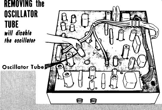
There are various methods of checking for the presence of positive feed back requiring the installation or readjusting of neutralizing circuits. One method disables the oscillator by removing the oscillator tube. With the oscillator disabled any presence of rf at the output of the transmitter, or as indicated by grid current readings, indicates that one of the amplifier stages is self-oscillating. The meter readings can be used to help locate the specific stage at fault. With the oscillator disabled, check the grid drive to the buffer-there should be none. If the buffer circuit uses tuning adjustments in the plate tank circuit, tune through the range while watching the grid-drive meter reading. If tuning the plate tank circuit develops grid drive, self-oscillation is indicated.
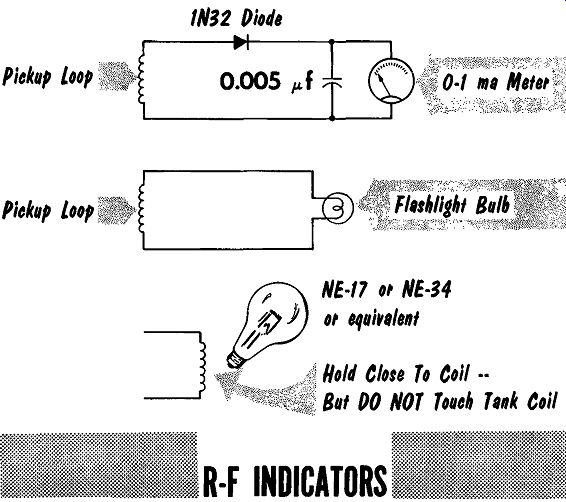
A method of checking the individual stage under suspicion removes the plate voltage to the amplifier tube. For tetrodes and pentodes the screen grid voltage must also be removed. The drive signal is applied to the input grid of the circuit as in normal operation. An r-f indicator is inductively coupled to the output tank circuit and the tank circuit tuned through its range. The presence of rf in the output circuit is indicated by a glow on a neon lamp or a meter reading of an r-f indicator. The presence of rf in the output indicates that positive feedback is present, requiring neutralization or adjustment of the neutralization circuit.
1N32 Diode
--
A similar method of checking individual stages without the use of an r-f indicator also requires removal of the plate voltage of the amplifier tube.
For tetrodes and pentodes the screen grid voltage must also be removed.
With the drive signal applied to the input grid of the amplifier stage, tune the output tank circuit; it should have very little, or no effect, on the value of input drive signal. A marked increase in the meter reading of grid drive while tuning the output tank circuit indicates the presence of positive feedback.
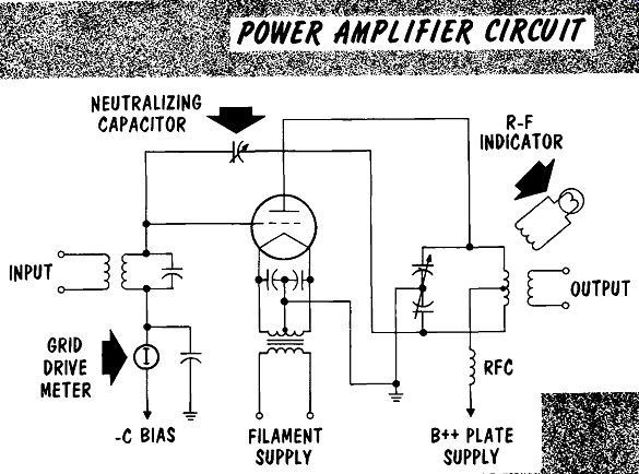
When adjustment of neutralization of an r-f amplifier is required the following steps can be taken:
WARNING: Use caution when working with the plate and screen supply voltages, particularly in the final stage, where lethal voltages may be present.
1. Remove the plate supply voltage. For tetrodes or pentodes also re move the screen grid supply voltage.
2. Couple an r-f indicator to the plate tank inductor.
3. Apply a drive signal to the input grid of the amplifier.
4. Set the adjustable neutralizing capacitor to minimum capacity.
5. Tune the output tank circuit for maximum on the r-f indicator. (This should be when the plate tank circuit is tuned to the same frequency as the input drive signal.)
ADJUSTMENT OF NEUTRALIZATION IN POWER AMPLIFIER CIRCUIT
6. Tune the neutralizing capacitor for a zero reading on the r-f indicator
7. Tune the plate output tank circuit throughout the tuning rang There should be a zero reading on the r-f indicator throughout t range.
8. Tune the plate output tank circuit throughout the tuning rang There should be no change in the grid drive reading.
9. Remove the r-f indicator and apply plate and screen voltage.
10. Check the circuit again, with the plate and screen voltage applied. With no drive signal, tune the plate output tank circuit throughout the range. There should be no grid drive reading.
---
For situations in which an r-f indicator is not available and the amplifier circuit has a grid drive meter in the input circuit, the following abbreviated neutralization procedure can be used: Remove the plate supply voltage. For tetrodes and pentodes also remove the screen grid voltage. Tune the out put plate tank circuit until the grid reading suddenly changes. Adjust the neutralizing capacitor to remove the change or fluctuation. Rotate the out put tank circuit tuning capacitor, and readjust the neutralizing capacitor each time the grid reading changes. The stage is neutralized when the grid reading remains unchanged as the output tank circuit is tuned through the range.
When no amount of adjustment will completely neutralize the amplifier stage, the following possibilities can be investigated: long or open leads in the neutralizing capacitor feedback circuit, and undesired coupling between the input circuit components and the output circuit components due to improper or too-close placement. In higher-frequency circuits: un bypassed filament leads, poor, or no shielding between the input and out put circuits, and the neutralizing capacitor is too close to the strong electromagnetic field of the output circuit tank coil.
Parasitic Oscillations
As in an unneutralized r-f amplifier stage, parasitic oscillations make their presence known by creating an output at the final stage either with no oscillator drive signal applied to the buffer stage, or a signal output at a frequency other than that to which the transmitter is tuned. The parasitic oscillations may modulate the signal at the original frequency causing the output signal to have a rough tone. It is best to check stage by stage to find the stage containing the parasitic oscillations; then check the defective stage to find the component or lead causing the oscillations. A stage that contains parasitic oscillations will show a strong increase in plate current.
The excessive plate current can, in time, depending on its value, ruin the tube.
With no grid drive coupled to a stage, there should be no grid-current meter reading, and, depending upon the circuit, there should be a specific value of plate current. Tuning the input and/or output circuits should have no effect on the grid- or plate-current meter readings. If parasitic oscillations are present, grid current will flow and plate current will increase.
Be careful: plate current can increase to a dangerous value and quickly ruin the tube; be prepared to quickly remove power to the transmitter.
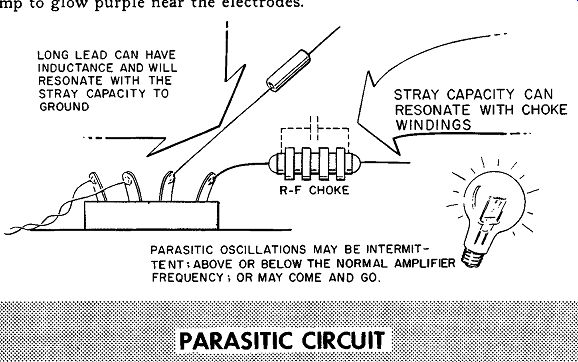
Upon locating the stage that contains the parasitic oscillation, the next problem is to locate the components or leads that cause the trouble. A neon bulb indicates parasitic oscillations by glowing when placed close to the field being generated by the undesired oscillatory circuit. Low frequency parasitic oscillations cause the neon lamp to ionize; however, the color is yellow instead of the usual pink, and the glow is near the glass envelope not on the electrodes. High-frequency parasitic oscillations cause the neon lamp to glow purple near the electrodes.
LONG LEAD CAN HAVE INDUCTANCE AND WILL RESONATE WITH THE STRAY CAPACITY TO GROUND STRAY CAPACITY CAN RESONATE WITH CHOKE WINDINGS PARASITIC OSCILLATIONS MAY BE INTERMITTENT, ABOVE OR BELOW THE NORMAL AMPLIFIER FREQUENCY; OR MAY COME AND GO.
-----------
Upon locating the stage containing the parasitic oscillations, a grid-dip oscillator is used to locate the components or portion of the circuit that is resonating, and the undesired frequency to which it is resonating. When tuning the grid-dip oscillator through the various bands of frequencies, look for a shallow dip. The undesired parasitic tank circuit usually works against stray capacity and is a low-Q circuit.
---------
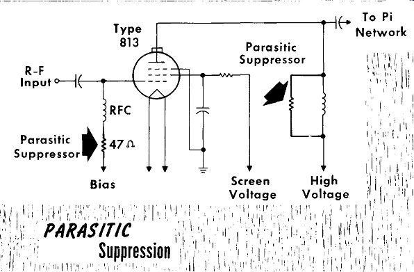
If the parasitic oscillation is low in frequency and in the grid circuit of the r-f amplifier, place a low value resistor (47-100 ohms) in series with the r-f choke. If the undesired resonant circuit is in the plate-circuit r-f choke, place a medium value resistor (8.2-12 K) across the r-f choke. In both cases, the resistor lowers the Q of the undesired resonant circuit to a value so low it will not oscillate.
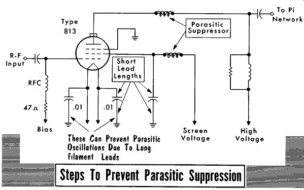
In triode r-f amplifiers (single-ended or push-pull) using neutralization, the wiring leads of the neutralizing circuit are prone to cause parasitic oscillations. The cure for this can be shorter wiring leads, and better placement of the leads (keep input grid and output plate-circuit leads as far away from each other as possible). In high-frequency circuits the use of heavier wire or a flat ribbon conductor reduces any undesired lead inductance, particularly in long leads. However, this is done at the expense of increased stray capacity due to the large physical size of the conductor, requiring extreme care in placement of the lead.
Another method of preventing parasitic oscillations in leads to tube sockets (typical is the screen lead to a tetrode or pentode) uses 5 to 10 turns of enameled wire wrapped around the outside of a low value resistor ( 47 ohms). The resistor is placed as close as possible (consistent with good construction practice) to the tube socket lug.
Low- and medium-power tetrodes, such as the type 807, are susceptible to parasitic oscillations in the plate lead from the cap on top of the tube.
The cure here is a low value resistor (47 ohms, 2 watts) with 5 to 10 turns of enameled wire wound around the outside.
These Can Prevent Parasitic Oscillations Due To long filament leads Parasitic Suppressor Screen Voltage High Voltage Steps To Prevent Parasitic Suppression
-------
The following procedure can be used for checking circuits contain parasitic oscillations where the plate current is so high that power must be removed. Place an adjustable transformer in series with the power supply to allow control of plate and screen grid voltage. Filament voltage must be kept constant; if necessary use an external filament transformer. Place a dummy load on the output of the circuit-a lamp bulb will do. Use a value lamp bulb as determined by the tube ratings-for example, an 807 could use a 100 watt bulb. With no grid drive signal, slowly increase the plate and screen voltage to the circuit. The instant it breaks into parasitic oscillations check the plate current. If it is over the safe value, reduce the setting of the adjustable transformer, trying to maintain the parasitic oscillations while not exceeding a safe value of plate current. With the oscillations continuing and plate current at a reasonable value, proceed to troubleshoot the circuit as previously discussed.
SUMMARY
Repairing a defective transmitter requires the same reasoning and logic applied to a defective receiver. Try to reason the difficulties by observing with three of our senses-sight, sound, and smell.
Meter readings should be taken and compared to the correct readings taken during normal transmitter operation.
Audible tests can be made for arcing and for the "pull-in" or "drop-out" noise of relays.
The buffer stage in many transmitters is fixed-tuned, and has no tuning adjustments.
With sufficient drive to the input of the final amplifier, a severe dip in the output tuning resulting in a low level of plate current indicates loss of the output load.
R-f amplifier circuits in which the input and output frequencies are identical can cause the amplifier to oscillate.
Negative feedback, called neutralization, is used to remove the undesired oscillations.
With the oscillator disabled, any presence of rf at the transmitter output indicates that a stage is self-oscillating.
During adjustment of neutralization of an r-f amplifier, observe caution when working with plate and screen supply voltages, particularly in the final stage where lethal voltages may be present.
Parasitic oscillations make their presence known by creating an output at the final stage with no oscillator drive signal. They may modulate the signal at its output frequency to give the output signal a rough tone.
A grid-dip oscillator helps to locate the parasitic oscillator circuit.
Low value resistors are used in circuits prone to break into oscillation.
These reduce the Q of the circuit, preventing oscillation.
REVIEW QUESTIONS
1. Name two obvious, but often overlooked, problems that could cause defective transmitter operation.
2. Describe the visible checks that should be made of a defective transmitter.
3. What advantage have we in testing a defective AM-CW transmitter?
4. What type of checks can be made in a defective transmitter that uses either an external crystal or the built-in, tunable oscillator circuit?
5. What quick checks can be made of the speech amplifier and modulator circuits of an AM transmitter?
6. Why must safety precautions be observed when neutralizing r-f amplifier circuits, particularly final amplifiers?
7. Briefly describe the abbreviated method for neutralizing a circuit with no r-f indicator.
8. What are some of the possible problems that can be investigated when no adjustments will completely neutralize an amplifier?
9. What precautions must be taken regarding tube plate current in a circuit containing parasitic oscillations?
++++++++++++++++++++++++
Checking Transmitter Output
Assuming you have checked your transmitter-final-output-stage meter readings, but, after calling a station there is no returning answer, the obvious thought arises: "Is the transmitter signal getting out?" Depending upon the situation, an amateur station may change frequency within the band, or change bands. A commercial station may have to change to other specific frequencies, usually denoted as calling frequencies. If other stations can be raised on these other frequencies ask for signal reports. Signal re ports enable you to evaluate your present reports with previous reports.
When no response is received after numerous calls, the problem may be remedied by arranging (via the telephone) with a local station to monitor your signal and report as to its strength and clarity.
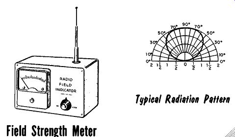
RADIO Field INDICATOR Field Strength Meter Typical Radiation Pattern
----
When the reports are adverse, and the output of the transmitter is either missing, or reduced from normal, or altered in any way, various devices and checks are made to localize the difficulties. One method uses a field strength meter. This is a low-Q resonant circuit with a calibrated dial and a crystal detector applying the output directly to a sensitive meter, or to a transistorized amplifier whose output is applied to a meter. A portable antenna with dimensions close to those of the operating frequency is used for signal pick-up. A field strength meter must be used no less than five wavelengths away from the transmitting antenna, preferably further. The field strength meter measures the intensity of the radiated field. Traveling away from the transmitter while measuring at regular intervals, allows a plot of the radiation pattern. This plot shows any dead-spots or how efficient a directional antenna is performing in addition to checking the strength of the radiated signal.
To check within the station area, a simple r-f monitor can be used. This is a low-Q resonant circuit (tuned to the operating frequency) using a crystal detector and a pair of earphones or a meter as a load. Because of an area of high radiation, a short (18 inches or less) lead will act as a suitable antenna. For use in the immediate area, the r-f monitor will permit readings indicating the presence and strength of a radiated signal.
From Transmitter
VSWR Indicator Input Output R-F Ammeter or R-F Voltmeter
------
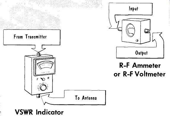
A VSWR indicator placed in the transmission line will indicate any change in the VSWR measurements. A drastic change indicates a defect in either the transmission line or the antenna. To isolate the trouble where the antenna is readily available, a dummy load capable of handling the transmitter output and having the same impedance as the antenna is placed at the end of the transmission line. This determines whether the difficulty is in the line or antenna. If the VS WR reading returns to normal, it indicates the antenna is at fault; if the reading remains changed, it indicates the trouble is in the transmission line.
An r-f ammeter or r-f voltmeter inserted between the transmitter output and the transmission line is often used to tune for maximum output or for setting the output to within prescribed limits. An r-f ammeter consists of a thermocouple built-in to a sensitive d-c meter. The thermocouple, two dissimilar metals, is placed alongside a resistance wire through which the r-f current flows. The heat of the resistance wire causes the thermocouple to generate a low-value d-c voltage that is proportional to the r-f current.
The d-c voltage of the thermocouple is applied to the d-c meter, which is calibrated in power readings. A similar instrument is the r-f voltmeter in which a portion of the output current is developed across a calibrated load resistor, rectified by a crystal diode, with the rectified voltage applied to a calibrated d-c meter. The r-f ammeter or r-f voltmeter readings indicate whether there is any transmitter output and whether it is of the proper output level as compared to previous readings.
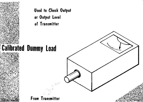
A quick check for transmitter output is the use of a dummy load containing a meter providing calibrated output readings. The dummy load is placed directly at the output of the transmitter to check for an output or to check the output level. If the output is present in its correct value, the transmission line is replaced, and the dummy load placed on the output of any succeeding device placed in the transmission line. Most often the output of the transmitter is coupled to a bandpass filter to reduce or eliminate undesired harmonic frequencies. The dummy load is then placed at the output of the filter to be sure there is no loss between the transmitter output and the filter output. Another device often found in the transmission line is an antenna changeover relay used to switch the antenna between the receiver and transmitter. This too should be checked by placing the dummy load at its output to be sure there is no loss between the transmitter and the relay output.
To Check Output or Output Level of Transmitter
Calibrated Dummy Load
From Transmitter
-------
Any reports or checks of a full-strength, unmodulated carrier output from an AM transmitter indicates loss of modulation within the transmitter modulation circuits. These will be discussed later in the book.
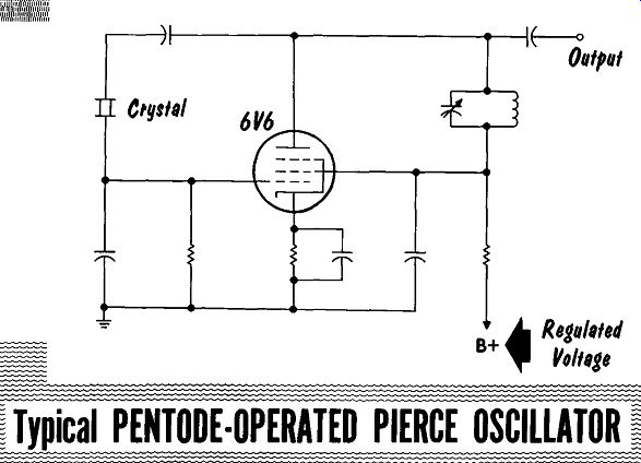
----------- Typical PENTODE-OPERATED PIERCE OSCILLATOR
Frequency Stability
Legal requirements are that the transmitter output frequency stay either within sharply-defined limits or on a specified frequency. From the time a transmitter is first turned on, a warmup period should be allowed for the oscillator circuit components to steady down. The transmitter can be used within three minutes, but at least one-half hour should be allowed for proper oscillator stability. Following a one-half-hour warmup time, any continued change in frequency constitutes a drifting oscillator which re quires repair. The factors affecting stability must be recognized to effect any repair of a drifting oscillator circuit.
Assuming an oscillator circuit that has been drift-free but is now drifting, the following areas should be checked for any changes. The most important factor is heat. Any reason for a sudden or continuous change in temperature must be checked. Where a fan is used for cooling, be sure it is operating properly, and that all ducts and perforations are free-and-clear to allow unimpeded air flow. Another important factor is plate and or screen voltage, which should be from a regulated voltage source. if possible. A minimum form of regulation is obtained from a gas tube or zener diodes. To check the source, place a meter on the output and observe the reading for any voltage fluctuations.
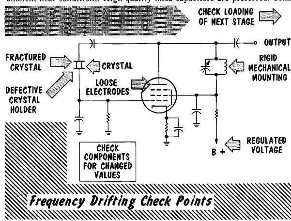
------
Too-close coupling of the oscillator to the succeeding stage permits any change in the succeeding stage to be reflected back to the oscillator. This varying load on the oscillator output can result in erratic frequency changes. Components must be snugly mounted to prevent any vibrations from moving them, in turn varying the output frequency. This is a particular problem in mounting the plate tank coil and capacitor. Another source of difficulty is a gradual changing of a component value due to heat. Two examples are resistor values and small-value capacitors. Resistors should be mounted free-and-clear to allow adequate ventilation. Capacitors should be of high quality, designed to maintain a constant capacity under high ambient-heat conditions. High-quality mica capacitors are preferred. Some circuits are designed to use negative- or positive-coefficient capacitors to overcome drift: these should be checked to be sure they are operating as rated. Ovens used to mount the crystal on the oscillator should be checked with a thermometer to insure that it is maintaining a constant temperature. The crystal can be checked for cracks or chips, and the crystal holder can be inspected for possible flaws.
An erratic change in oscillator frequency, particularly when the chassis is vibrated, may be a result of loose electrodes within the oscillator tube. To check this replace the tube. Allow one-half hour warmup for the replacement tube, and then gently tap the tube or vibrate the chassis to be sure the output frequency remains constant.
Frequency Measurement
Frequency measurements are required to determine any drift in the output frequency of a transmitter. There are various methods of measuring frequency, with the simplest and one of the best using a receiver. To check the output frequency of a transmitter requires that the receiver dial be accurately calibrated. The receiver can readily be calibrated by comparing the accuracy of its dial calibration with reception of the signal broadcast by the National Bureau of Standards. The National Bureau of Standards broadcasts from station WWV in Washington, D.C., and WWVH in Puunene, Hawaii at 2.5 mhz and harmonics of this frequency. Signals are trans mitted at 2.5, 5, 10, 15, 20, and 25 mhz. These transmissions are coded to provide correct time plus information regarding propagation conditions. The frequency of transmissions is accurate to within 1 part in 100 million (1 part in 10'). This means that at 10 mhz the transmitter frequency will be off by no more than 0.1 cycle in every ten million cycles. Although this accuracy is lost in transmission over distances involving sky wave reception, it is still a remarkably accurate signal suitable for calibrating all but the most demanding equipment requirements.
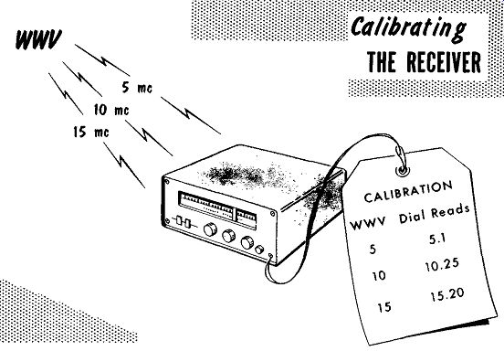
-----------
With the receiver tuned to WWV, the dial is calibrated by noting the difference in dial reading, and the transmitted frequency, and listing it on a sheet of paper. This difference will probably vary with each band. It is best to calibrate with the nearest-value WWV signal that falls on the band being checked. Some receivers have mechanically-constructed dial devices that allow repositioning of the dial pointer or dial scale to calibrate the receiver. Others have local oscillator-trimmer capacitors that are used to reset the local oscillator to zero beat with the signal of WWV.
A secondary standard is a crystal oscillator using a 100 -khz crystal with a buffer amplifier whose output is rich in harmonics. The secondary standard can be an external accessory or it can be built-in to the receiver. The output of the secondary standard is coupled to the antenna input of the receiver, providing checkpoints every 100 khz on the dial. At intervals, the secondary standard should also be checked against WWV for calibration.
To calibrate the transmitter, only the oscillator circuit need be operating.
Many transmitters have provisions that allow B+ to be applied only to the oscillator circuit for checking or comparing the oscillator frequency.
The output of the oscillator alone is usually sufficient to radiate over a short area in an enclosed room, allowing its signal to be picked up by the calibrated receiver. With the receiver set for CW reception, tune it for zero beat with the transmitter oscillator signal. To be sure it is the correct signal, turn the transmitter oscillator on and off; the beat note should go on and off in step. To overcome inaccuracy in the alignment of the receiver's BFO, turn the BFO off, and operate the receiver with AGC and the r-f gain reduced for a low reading. Carefully tune the receiver until the S meter reads maximum for the reception of the carrier signal. Note the dial setting -- it should be the same as that obtained using the BFO.
TRANSMITTER SIGNAL FROM OSCILLATOR RECEIVER
CHECKING FREQUENCY
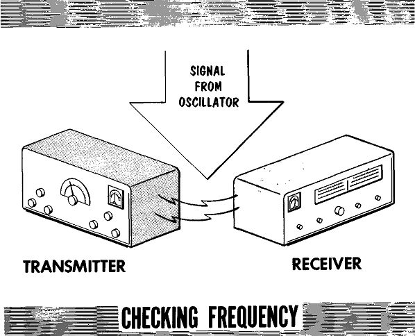
----- Zero Temperature Alignment Coefficient Trimmer RFC To Buffer
Amplifier Regulated B+
Variable Frequency Oscillator
In the VFO circuit shown, the tank circuit is tuned to resonance by the tank coil and a zero-temperature-coefficient fixed capacitor. To vary the oscillator over the desired range, a small value variable capacitor is placed parallel to the tank circuit. Another small value variable capacitor is paralleled to the tank circuit; it is used for alignment purposes. Although the oscillator is tuned through only one band of frequencies, the frequency multiplier stage will provide an output at harmonic frequencies. The harmonic frequencies are also calibrated on the dial.
Reduced output may be caused by reduced feedback, a defective tube, or reduced voltage. Reduced feedback will usually be caused by any change (usually shorted turns) in the number of turns in the feedback portion of the coil, which will also have an effect on the output frequency. The most likely cause is an aged tube with reduced emission and resulting reduced plate current. Another likely cause is reduction of either screen or plate voltage. Screen voltage changes can be caused by either a change in the screen dropping resistor, or a partial short circuit in either the screen bypass or B-plus bypass capacitor.
Reduced plate voltage can be caused by a partial short in the B-plus bypass capacitor, or a shorted screen bypass capacitor. A shorted coupling capacitor may reduce the plate voltage. This will be determined by the design of the grid circuit of the following buffer amplifier.
----------
---------
Reduced B-plus voltage reading can be either as a result of a short circuit in the oscillator, or a defect in the B-plus source. To check, lift the B-plus lead from the source and measure the value of B plus. If it rises to its regular value, it indicates the defect is in the oscillator circuit. If it remains reduced in value, it indicates the defect is in the voltage source.
Complete loss of output can be quickly checked by taking a reading of the grid bias; it will be zero if there is no oscillation. A plate voltage reading should then be taken. A high plate-voltage reading indicates the possibility of an open cathode return through the tank coil. A zero plate-voltage reading indicates an open r-f choke in the plate circuit, or a shorted B-plus bypass capacitor.
With the correct values of plate and screen voltage, check for an open grid leak capacitor or resistor. Also, defects in the tank circuit causing the loss
Regulated B+ of oscillations can be shorted trimmer, tuning, or tank capacitor, or an open coil.
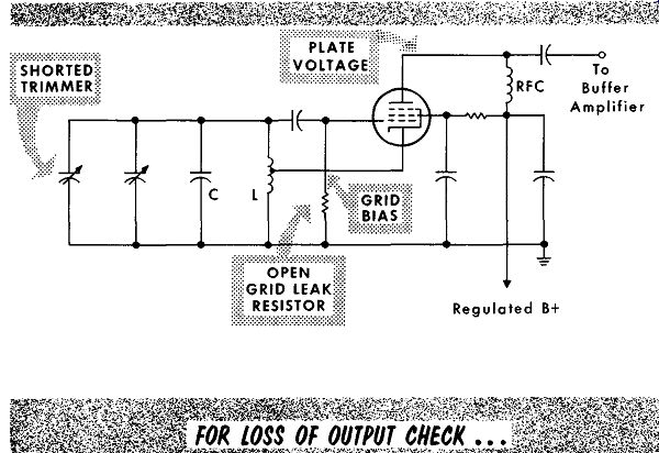
-----------
For drastic off-frequency oscillation, with the transmitter turned off, use a grid dip oscillator to check if the tank circuit is resonant at the frequency indicated on the dial. Any small change in frequency can be corrected with the alignment trimmer. A drastic change requires checking for changed values of the tank circuit components. Any tank circuit component which changes value drastically requires replacement.
Crystal Oscillator
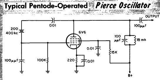
---------
A typical Pierce crystal oscillator is shown above. It has high stability and requires no tank circuit, forming a simple and often used crystal oscillator circuit. A small amount of cathode bias is used to prevent the plate current from exceeding normal limits when the crystal is removed from its holder. The isolating capacitor between the plate and the crystal is used only to remove B plus from the crystal holder.
With an equivalent diagram of the crystal circuit, it can be shown that the Pierce oscillator operates in a manner similar to the Colpitts oscillator.
This Pierce oscillator circuit uses the interelectrode capacitances of the tube to obtain the Colpitts configuration. In order to minimize the effect of having to depend on the interelectrode capacitances, which may vary from tube to tube, designers sometimes incorporate a fixed capacitor from plate to grid, thereby making the oscillator less sensitive to a change in inter electrode capacitance.
Reduced output may be the result of a defective tube, reduced voltages, or a defective crystal. An aged tube with reduced emission will also cause reduced output. An open cathode-bypass capacitor will result in degeneration to lower the output. An aged crystal that has lost resiliency can also be a reason for low or erratic output. A shorted isolating capacitor applying B plus to the crystal may cause it to become defective and result in a reduced or erratic output. An open isolating capacitor between the plate and crystal may allow sufficient feedback through leakage to sustain oscillation, but the output will be intermittent or low. A partial short circuit in either the screen or B-plus bypass capacitor, or an increase in the value of the screen dropping resistor, will result in low screen and plate voltages to provide reduced output. A shorted coupling capacitor may result in reduced plate voltage. This would be determined by the design of the grid circuit in the succeeding stage.
A reading of reduced plate and screen voltages can be either a result of a defect in the oscillator circuit or in the B-plus source. To determine which, lift the B-plus lead to the circuit. If the B-plus voltage rises to its correct value, the defect is in the oscillator: if it remains low, the defect is in the voltage source.
For a complete loss of output check all voltages. A high plate-voltage reading will indicate an open cathode resistor or open tube. A loss of cathode bias voltage will probably be the result of a shorted bypass capacitor. A shorted screen-bypass capacitor or an open screen dropping resistor will result in a loss of screen voltage. A shorted B-plus bypass capacitor will result in the loss of both screen and plate voltage. Take a B-plus reading on the plate side of the crystal holder to check for a shorted isolating capacitor. Application of B plus to the crystal may damage it, causing loss of output. A heavy blow or sharp vibration can fracture the crystal, resulting in loss of output. A typical "pressure sandwich" type mount is shown in the illustration. Never attempt to repair a fractured crystal. They are easily replaced. A change in output frequency, erratic operation or spurious signals from 20 to 60 khz on either side of the carrier frequency may be the result of a crystal damaged by shock or vibration, or a defective crystal mount.
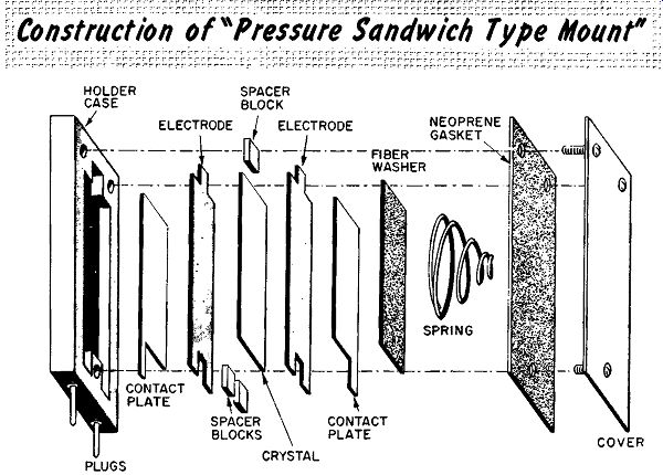
------
SUMMARY
A field-strength meter is a low-Q resonant circuit with a calibrated dial and a crystal detector applying the output to a sensitive meter. With a portable antenna with dimensions close to those of the operating frequency, the meter is used to check signal strength.
To check within the station area, a simple r-f monitor can be used. This is a low-Q resonant circuit tuned at or near the operating frequency.
Being used in a high radiation area, it requires a short (18 inches or less) antenna.
A VSWR indicator in the transmission line will indicate any change in the VSWR measurements.
A quick check for transmitter output is a dummy load containing a calibrated meter for measuring a rectified portion of the output signal.
A transmitter can be used within three minutes after turning it on, but at least one-half hour should be allowed for proper oscillator stability.
An accurate method of calibrating a receiver is to compare its dial calibration with reception of signals from the National Bureau of Standards broadcasts from WWV and WWVH. The receiver dial may be calibrated by noting the difference in dial readings of WWV or WWVH, and the dial calibration. Some receivers use mechanical dial scale or dial pointer positioning devices; others may use a resettable, local oscillator-trimmer capacitor to allow a zero beat with WWV or WWVH. A grid-dip oscillator is useful in checking the resonant frequency of oscillator tank circuits.
A heavy blow or sharp vibration can fracture a crystal and cause complete loss of output. No attempt should be made to repair a fractured crystal; they are easily replaced.
Fractured crystals can cause less obvious difficulties such as erratic operation or spurious signals on either side of the carrier frequency.
REVIEW QUESTIONS
1. What is the minimum distance that a field-strength meter can be placed from a transmitting antenna?
2. How can we use a dummy load to check for difficulties in either the transmission line or antenna?
3. Describe the construction and action of an r-f ammeter in measuring r-f current.
4. What would reports of 3 full-strength unmodulated carrier signal indicate for an AM transmitter?
5. What constitutes a drifting oscillator?
6. Name the most important factor to check for in a drifting oscillator.
7. How are negative, or positive coefficient capacitors used to combat drift in an oscillator?
8. In using receivers to test the output of a transmitter, how can we check for accuracy of the BFO?
9. What is the purpose of the capacitor between the crystal and the plate of the tube in a Pierce oscillator?
++++++++++++++++++++++
Buffer Amplifier
The buffer amplifier is used to provide isolation between stages, usually between the oscillator and frequency multiplier stages. The output tank circuit is tuned to the same frequency as the input. Being biased class A, its grid circuit always presents a high impedance to the preceding stage to maintain a constant load. To allow changing the output power of the buffer stage, the screen voltage is taken from an adjustable voltage divider using a high-wattage potentiometer as a drive control. This permits adjustment for a specific output, or drive level (measured in the grid of the succeeding stage), with varying input levels.
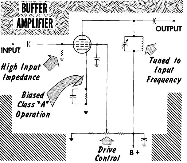
-------------
To test for reduced output, check for low values of plate and screen voltages. Low plate voltage may be a result of a partial short in the B plus bypass capacitor. Low screen voltage may be the result of a partial short in the screen bypass capacitor, or changed values in the screen voltage-divider network. An open cathode bypass capacitor will cause degeneration, slightly reducing the output signal level. An aged tube with low emission or reduced input to the grid circuit are other possibilities that must be checked.
With no output from the amplifier, check for complete loss of input signal.
An open plate circuit due to an open cathode resistor is indicated by high plate voltage. Loss of plate voltage could be a result of a shorted B-plus bypass capacitor. A remote possibility is an open coil winding, but more likely the lead connection at either end of the coil may be defective. Any reading of a positive voltage on the grid indicates a shorted coupling capacitor.
When a partial or complete loss of voltage is present at the B-plus terminal, a quick check to determine where the fault lies is to lift the B·plus lead from the terminal. With the B-plus lead lifted, read the B-plus value. If it is still low, the difficulty is in the power supply; if it returns to normal, the difficulty is in the amplifier circuit.
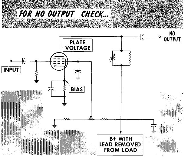
------------
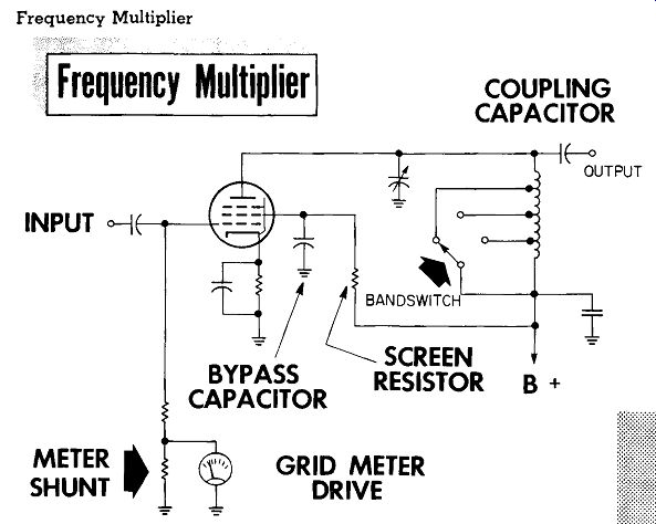
---- Frequency Multiplier
Should the buffer amplifier be operating correctly but provide no control over the drive to the succeeding stage, check the screen-grid voltage-divider network. An open circuit at the ground return would place the potentiometer and the resistor closest to the B-plus line as a series voltage-dropping circuit, with virtually no control over the screen voltage.
A frequency multiplier is used to provide output frequencies at multiples of the input frequency - one with twice that of the input being a doubler, and one with the output being three times that of the input is a tripler, etc.
An output frequency differing from input frequency does not often require neutralization. Depending upon circuit design, it may or may not have a tuned tank circuit at the input. When the output is band switched, the input is most often RC coupled, relieving the necessity of bandswitching the grid circuit. A current-reading grid-drive meter is used to measure input power. The output is usually tuned by measuring the grid drive to the succeeding stage; when tuned to resonance, it will provide maximum drive. To cover a wide range of frequencies the output tank circuit is usually band switched by a tapped coil.
To check for a reduced output signal, the obvious first step is to measure grid drive. Other checks are for a low emission tube and reduced screen and plate voltages. Reduced screen voltage can be the result of a partially shorted screen bypass capacitor or an increased-value screen series dropping resistor. Reduced plate voltage can be caused by a partial short in the B plus bypass capacitor. A small reduction of output could be caused by an open cathode bypass capacitor causing degeneration in the grid-cathode input circuit.
A complete loss of output from the buffer amplifier is indicated by loss of drive to the grid of the succeeding stage. In checking for a complete loss of output signal, the first step is to check for input drive on the grid current meter. With an input signal present but no output, check all ...
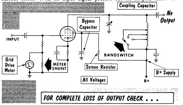
------------
... voltages. An open cathode resistor causes a loss of grid bias and a high plate voltage. A shorted coupling capacitor is indicated by a high positive voltage reading on the grid. A loss of screen voltage indicates either an open screen dropping resistor or a shorted screen bypass capacitor. A loss of plate voltage could be a shorted B- plus bypass capacitor or shorted tuning capacitor.
Difficulties in tuning or intermittent operation will usually center around the plate tank circuit and the bandswitch. A very shallow tuning dip indicates that the output circuit is heavily loaded by the succeeding stage.
A very sharp dip indicates no load on the output circuit. An intermittent bandswitch due to defective or dirty contacts can be checked by observation of the grid drive meter in the succeeding stage. While observing the meter, flex the bandswitch knob gently to determine any erratic output as a result of the bandswitch flexing. If the buffer stage does not tune normally check for an open bandswitch. A grid dip oscillator or absorption wavemeter is best for checking the tank circuit for correct resonant frequency. When checking the frequency be sure to check the bandswitch position, deter mining whether the knob may have loosened and possibly be set to the wrong band. For erratic tuning, check the tuning-capacitor mechanical arrangements. Most often the variable capacitor is connected to the tuning shaft by an insulated coupling that could come loose. To check the coupling, check the set screws of both the coupling and the knob at each end of the shaft.
R-F Power Amplifier
Most often the r-f power amplifier stage is the final stage of the transmitter.
Coupling the output to a succeeding stage of higher power, through a conventional tank circuit instead of a pi network, would make an r-f power amplifier a driver stage. In the circuit shown the cathode is applied directly to ground and bias is derived by grid-leak method in an RC coupled input.
Parasitic suppressors are used at the control grid and plate cap connections.
The output circuit is often metered to read both plate and screen current although it is labeled plate current.
POWER AMPLIFIER_ STAGE
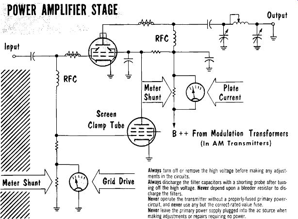
----- Always turn off or remove the high voltage before making
any adjustments in the circuits.
Always discharge the filter capacitors with a shorting probe after turning off the high voltage. Never depend upon a bleeder resistor to discharge the filters.
Never operate the transmitter without a properly-fused primary power circuit, and never use any but the correct-rated-value fuse.
Never leave the primary power supply plugged into the ac source when making adjustments or repairs requiring no power.
To regulate the screen voltage a clamp tube is placed between the screen grid terminal and ground. With a grid-drive signal to the amplifier, the resulting negative grid bias cuts off the clamp tube conduction. The applied signal causes the amplifier to conduct, and the resultant screen-grid current flow through the screen dropping resistor causes a voltage drop providing a reduced-value screen voltage. With no signal and reduced screen grid current, the screen grid voltage tends to reach the same high value as the plate voltage, which is too high a level for a screen voltage. With the loss of grid drive signal, the low self-bias value at the grid of the amplifier allows the clamp tube to conduct. With the clamp tube conducting, the screen voltage drops to approximately the same value caused by the amplifier tube conducting. The result is a regulated, near-constant screen grid voltage.
In checking for reduced output, voltage readings should be taken to determine if the reduction in output is a result of a reduction in any operating voltage. As previously mentioned, an obvious first step would be to check grid drive or loss of grid bias, both of which will be evidenced by the grid current meter reading. A low value of high voltage may be due to a defect in the modulator stage of an AM transmitter, a defect in the amplifier stage, or a defect in the power source. Low plate or screen voltage will probably be indicated by an excessive no-signal, plate-current meter ...
----------- 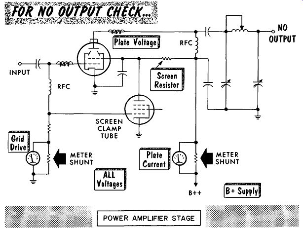
------------
... reading, the cause of which may be a partial short in the screen or high voltage bypass capacitors. Low screen voltage with no increase in screen current may be caused by an increase in the resistive value of the screen voltage-dropping resistor. A high screen-grid voltage would indicate a defective clamp tube or improper operating voltages to the clamp tube.
In checking for no output, with grid drive and grid bias present as indicated by the grid current meter reading, check for loss of plate and screen voltage. With zero plate and screen current reading in the plate current meter, check for the absence of high voltage from the modulator stage. An abnormally high plate-current meter reading with very low or zero screen and/or plate voltage may be caused by a shorted screen or high-voltage bypass capacitor.
Resonance in the plate circuit is normally indicated by the dip in plate current readings as the plate tank capacitor is tuned throughout its range.
It is always good practice not to apply full plate voltage suddenly, but to increase the voltage slowly, if possible, until the rated voltage is reached.
A simple plot of the various current readings over the tuning range will indicate whether the amplifier is tuned properly. The shape of the curve may tell where the trouble lies. Below is illustrated the characteristics for different values of loading.
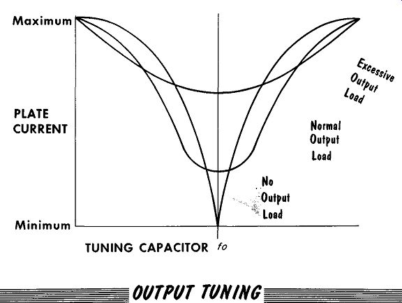
--
Tuning difficulties will vary with the problem. A very sharp dip with reduced plate-current reading will probably be due to a loss of the output load, such as a disconnected antenna, or an open coaxial cable or coaxial fitting. A dummy load should be placed directly at the output connector to check for loss of an output load. A short in the output load, or reduction in impedance causing a heavy load on the output stage will cause a wide, shallow tuning dip in the output circuit. The increased load will be reflected to the grid circuit, requiring increased drive from preceding stages to maintain the required grid drive in the r-f power amplifier. When the output tuning adjustments have no effect on the plate current reading, which remains steady, check for loss of grid drive signal on the grid current meter.
In all tuning procedures, whether tuning the output or input, be sure not to exceed the tube ratings, both in grid current values and plate and screen current values.
Transmission Line and Antenna
A properly terminated transmission line will have its output applied to an impedance equal to that of the transmission line. A properly matched transmission line will have its input see an impedance equal to that of the transmission line. With these conditions there will be no appreciable signal loss in the transmission line, and all the energy will be delivered to the antenna. Assuming a mismatch at the antenna, there will be energy reflected back down the transmission line to produce standing waves along the line. A VSWR indicator (p.2-87) inserted in the line is used to adjust the antenna for an impedance match with the transmission line, as indicated by the lowest VSWR reading on the meter.
A high VSWR reading can indicate difficulties in either the transmission line or the antenna. Various different types of transmission lines that may be encountered are shown in the illustration. The majority of transmission lines in use are manufactured coaxial- or ribbon-type lines with constant impedance. The difficulty in the transmission lines is usually due to broken connections to the antenna, poor or broken connections at the coaxial connectors, and loose or defective coaxial connections or connectors. To check the transmission line, remove the connections to the antenna and insert a dummy load. With a matched dummy load, any high VSWR reading indicates the difficulty is in the transmission line, while a low VSWR reading indicates the difficulty is in the antenna.
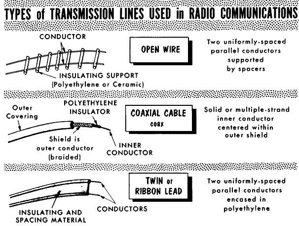
---
CONDUCTOR OPEN (Polyethylene or Ceramic)
Two uniformly-spaced parallel conductors supported by spacers
Outer Covering
POLYETHYLENE INSULATOR COAXIAL CABLE coo outer conductor (braided)
INNER CONDUCTOR
Solid or multiple-strand inner conductor centered within outer shield
INSULATING AND SPACING MATERIAL TWIN or RIBBON LEAD CONDUCTORS
Two uniformly-spaced parallel conductors encased in polyethylene
---------------
With the transmission line known to be good, a high VSWR reading indicates a defect in the antenna. If the antenna is designed specifically to match the impedance of the transmission line, a high VSWR reading indicates such defects as broken leads, broken or missing elements in a ground plane, etc. If the antenna uses a matching section to match the impedance of the antenna to that of the transmission line, a high VSWR reading is probably due to a defect or change in the matching section.
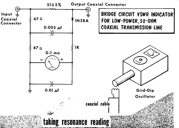
-----
A grid-dip oscillator can be used to check an antenna for its resonant frequency. The transmission line is removed from the transmitter. For coaxial lines a portion of the inner conductor is bared and coiled to form a two-turn loop with the end soldered to the outer braid. For 300-ohm transmission line the ends are bared and twisted for a two-turn loop. The grid-dip oscillator is coupled to the loop on the end of the transmission line. Starting at the highest band on the grid-dip oscillator, the frequency of the various dips are noted. The lowest frequency at which a dip is read, is the resonant frequency, while other dips are harmonics.
Resonance readings and VSWR readings will vary with the types of antennas. High-Q antennas, such as Yagis, will resonate sharply at specific frequencies and provide higher VSWR readings off the resonant frequencies. Low-Q antennas, such as long line or basic dipoles, will tune broadly at resonant frequencies and provide a slight increase in VS WR off the resonant frequencies.
Speech Amplifier Where meter readings indicate an AM transmitter has an r-f carrier output but weak, distorted, or no modulation, the usual first check is to start from the input or speech amplifier stage towards the output or modulator stage.
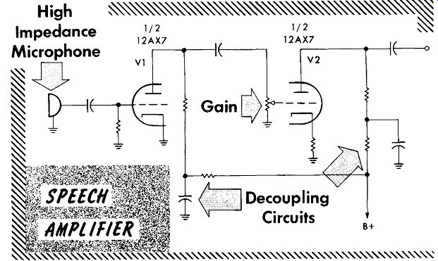
---------
The speech amplifier stage is a high-gain voltage amplifier used to build up the input signal voltage from the microphone to a level suitable to apply to a driver or low-power audio-output stage.
The input circuit is usually a high impedance circuit to match a crystal microphone or other high impedance types of microphones. Low impedance microphones are usually found in mobile installations requiring rugged carbon microphones. Their requirements of special input circuits restricts their use. The microphone can be checked by applying the output to an audio signal tracer, or by using a substitute microphone. The use of a substitute microphone in place of a defective microphone is quickly checked by observing the modulation stage plate-current meter readings. The presence of plate current fluctuations when talking into the substitute microphone, will indicate that modulation has been restored.
Reduced or distorted output can be checked by taking voltage readings.
Low plate voltage is caused by an increase in the resistor values of either the decoupling resistors or plate load resistors. Another cause is a partial short circuit of either decoupling filter capacitors. Distortion at the micro phone input to the grid circuit has to be checked with an audio signal tracer. Distortion at the input of the second stage can be checked by a voltage measurement for the presence of positive voltage at the grid of V2.
Any positive voltage present is due to a shorted or partially-shorted coupling capacitor.
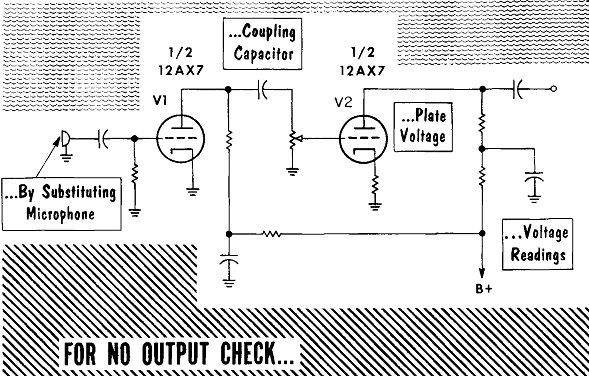
----- A 60-cycle hum that cannot be changed in value with the
gain control indicates an open or floating grid at tube V2, Some control over
the hum indicates an open grid at the input of tube V A 120-cycle hum at an
audible and annoying level can result from an open, decoupling-network fitter
capacitor. If the gain control has no effect on the hum, it is probably being
developed in the plate circuit of V2. If the gain control does have an effect,
the hum is probably being developed in the plate circuit of V1. Depending upon
the chassis layout and circuit gain, an open decoupling capacitor in the plate
circuit of V1 or V2 can cause positive feedback with its attendant bow and
squealing.
A complete loss of output can be checked by taking voltage readings. The first check point should be the tie point where B plus is applied through the decoupling resistors to the plate circuits of both tubes. If no voltage is present the lead from the power source should be lifted. If the lead from the power source resumes its full voltage value when lifted, it indicates the difficulty ties in either (or both) of the two pre-amplifier stages. Should the voltage at the lead from the power source still read zero, the power supply circuits should be checked. Loss of plate voltage to either tube can be due to open decoupling or plate load resistors, or shorted, decoupling filter capacitors. The presence of any positive voltage at the grid of V2 may cause such heavy conduction, and consequent plate voltage drop across the plate load, as to provide a zero or near-zero plate voltage reading. A high plate voltage reading on the plate of V2 may be due to an open cathode resistor.
SUMMARY
A buffer amplifier is used to provide isolation between stages. Being biased class A, its grid presents a high impedance to the preceding stage to maintain a constant load.
To change the buffer output power, the screen voltage is taken from an adjustable voltage-divider, high-wattage potentiometer.
A frequency multiplier is used to provide output frequencies at multiples of the input frequency. An output twice that of the input is a doubler, one with three times that of the input is a tripler, etc.
Loss of output of the buffer, or frequency multiplier stage is noted by loss of grid drive to the succeeding stage.
Most often the r-f power amplifier stage is the final stage of the transmitter.
Coupling the output to a succeeding stage of higher power would make an r-f amplifier a driver stage.
The output circuit of the r-f amplifier is often metered to read both the plate and screen current although it is labeled plate current.
To regulate screen voltage, a clamp tube is placed between the screen grid and ground.
In AM transmitters, the loss of high voltage to the r-f amplifier may be as a result of a defect in the modulator circuits.
Tuning difficulties vary. No output load is indicated by a very sharp dip in plate current; an excessive load will cause a very shallow dip; no change in plate current could indicate a loss of the input drive signal.
A grid-dip oscillator can check an antenna for its resonant frequency.
The speech amplifier is a high-gain voltage amplifier used to build up the input signal voltage from a microphone to a level suitable to apply to a driver for a low-power audio-output stage.
Mobile installations usually use rugged carbon microphones. The low impedance nf the carbon microphone requires special input circuits.
REVIEW QUESTIONS
1. When varying the drive control of a buffer amplifier, where do we read the indications of the change in drive?
2 Describe the checks that should be made of the knob, the shaft, and the coupling to the variable capacitor of the frequency multiplier circuit.
3. What type of output circuit is most likely to be found when the r-f amplifier is being used as an r-f power amplifier? A driver?
4. Briefly describe the action of the clamp tube in regulating the screen grid voltage of an r-f amplifier tube.
5. In tuning the output of the r-f amplifier, describe some of the possible causes of a very sharp dip. A very shallow dip. No dip.
6. What determines a properly matched transmission line?
7. In taking VSWR readings, what is desirable-a high reading or a low reading?
8. In VSWR readings what does a high reading indicate? A low reading?
9. What are the indications of an AM transmitter that signifies possible troubles in the speech amplifier circuits?
++++++++++++++++++++
Driver
INPUT Plate and Screen Voltages
- Transient Protection Capacitor
Open cathode resistor NORMAL: Shorted transient protection capacitor
ZERO: Open driver transformer short between turns, and metal core of driver transformer, shorted by B+ bypass capacitor
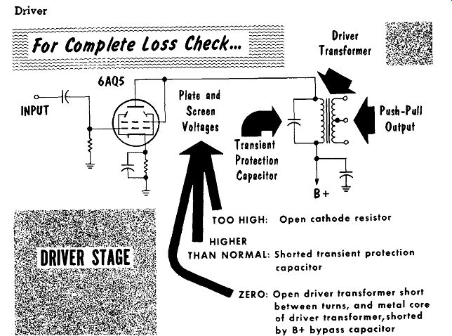
The driver stage is used to convert the signal voltage output of the speech amplifier stage to a power output capable of driving the modulator stage.
To achieve power for drive, a power amplifier tube is used in a triode connection to provide the low plate impedance desired in a driver amplifier.
The output is coupled to the modulator stage by a driver transformer with a center-tapped secondary to provide push-pull output. A small value capacitor with high voltage rating is placed across the primary of the driver transformer to protect the transformer against high voltage transients developed by the collapsing magnetic fields created by a signal voltage peak. The capacitor also acts as a tone control, reducing the output of high audio frequencies.
For low or distorted output, check for a partial short in the B-plus bypass capacitor, causing a reduced plate screen voltage. A partial short in the transient protection capacitor across the driver-transformer primary winding can cause a reduced and or distorted output. Distortion can be caused by a shorted coupling capacitor placing a positive voltage on the grid. If the grid goes sufficiently positive, it will draw excessive plate current causing the plate to glow red. A shorted cathode bypass capacitor will remove the grid bias and, cause distortion by having the tube operate on a nonlinear portion of the plate-current grid-voltage curve. An open cathode bypass capacitor will cause degeneration and a slight reduction in the output level.
Modulator Stage
Caution Note: The high voltages present in the modulator stage are the same as those present in the r-f power amplifier stage, and require that the same precautionary measures be strictly observed.
The modulator stage in a plate modulation system is a high power audio amplifier. The modulation transformer is carefully designed to have the primary winding match the plate impedance of the modulator tubes, and the secondary winding is designed to have it match the power amplifier tubes of the final r-f power-amplifier stage. The high-power, modulator amplifier circuit is prone to parasitic oscillations in the grid and plate circuits. To prevent the outbreak of parasitics, low value resistors with a few turns of wire wrapped around them are inserted at the grid and plate leads as parasitic suppressors. To get the power required to modulate the final, the types of tubes used in the modulator are usually the same types as those used in the final r-f amplifier stages. Plate current is monitored to check the circuit operation and to observe the signal fluctuations of the meter as a modulation monitor. The capacitor across the secondary of the modulation transformer acts to prevent high voltage transients from breaking down the insulation between the transformer windings and the transformer laminations. The push-pull circuit requires external bias to place the grids at the plate current cut-off point for class B operation.
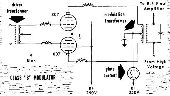
-------
To check for weak or distorted output, check the grid-bias voltage reading to be sure the tubes are operating on the correct portion of the plate-current grid-voltage curve. Make sure both tubes are operating correctly and have matched or closely matched values of mutual conductance. If one tube is defective it causes the other tube to try and maintain the entire output alone. An increased plate current reading and a reduced plate voltage reading could be the result of a partial short circuit in the plate voltage bypass capacitor.
Reduced screen voltage may be the result of a partial short in the screen voltage bypass capacitor. A cause for both distortion and reduced output would be a partial short in the transient suppressing capacitor across the secondary winding of the modulation transformer, or shorted turns in the primary or secondary winding of the transformer.
Complete loss of output is best checked by taking readings of all operating voltages. With no signal input, check the grid-bias voltage at the grids of the tubes. If no voltage is present, check for the presence of the bias voltage at the center tap of the secondary winding of the driver transformer.
If no bias voltage is present at the center tap, check the external bias voltage source. If the bias voltage is present at the center tap, check for an open transformer winding. For a loss of screen voltage, check for a shorted, screen bypass capacitor or a loss of voltage from the screen voltage source.
With the meter indicating zero plate-current flow, check for loss of plate voltage at the plate voltage source. Excessive plate current and zero plate...
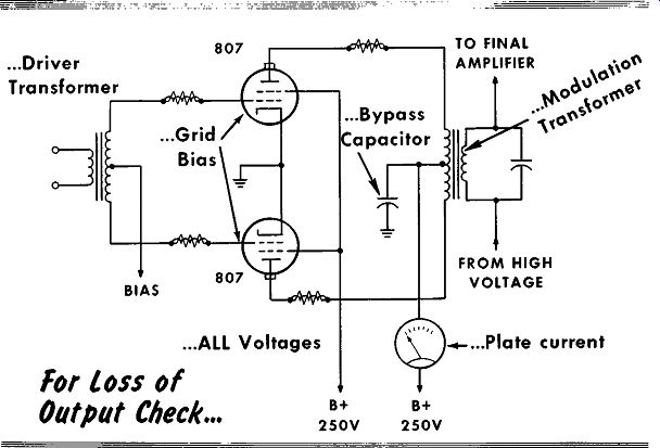
------------
...voltage indicates a shorted, plate-voltage bypass capacitor or turns shorted to the laminations in the modulator-transformer primary winding. A shorted, transient suppression capacitor would permit all correct tube voltage readings and allow the high voltage to bypass the modulation transformer secondary winding. The only indication of this would be a slight increase in the high voltage to the r-f power-amplifier stage due to the loss of the voltage drop across the transformer winding.
Reactance Tube Frequency Modulator
By having the plate voltage lead the grid voltage by 90°, a tube can act as an inductor and appear to have the same reactance exhibited by an inductor.
Paralleling the inductor of an oscillator tank circuit with the reactance tube, permits changes in the combined inductance represented by the tank circuit inductor and the reactance tube. Varying the value of reactance offered by the reactance tube will vary resonant frequency of the oscillator tank circuit, in turn varying the oscillator output frequency. Applying a ...
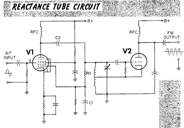
------
... modulating audio signal to the modulation grid of the reactance tube causes the oscillator to change frequency in step with the modulating signal to develop an FM signal.
Since any change or fluctuation in the source voltages for the modulator circuit would create changes or fluctuations in the output frequency, it is imperative that all operating voltages be well regulated. The frequency modulated output of the oscillator is applied to conventional r-f amplifier stages. The major requirement of the r-f amplifier stages is that they be tuned broad enough to prevent reduction in gain of the extreme frequencies in the wide band of frequencies developed in an FM signal.
In checking the reactance tube and oscillator stage for difficulties with the FM signal, all the succeeding r-f amplifier stages may be disabled. To check the linearity of the modulation a metered, pure d-c voltage (usually from a battery), capable of swinging from positive-through-zero-through-negative voltage, is applied to the modulator grid of the reactance tube. As the grid voltage varies from the extreme positive value to the extreme negative value, the oscillator output frequency should change in a linear manner.
To check the oscillator the output frequency is tuned in on a receiver with a carefully calibrated dial. As the voltage to the reactance tube grid is varied in equal-value small steps, the oscillator output frequency should vary in equal-value changes in frequency. The changes are read by following the output frequency with the receiver and noting the input voltage relation to the output frequency. The relation between grid voltage and output frequency is then plotted - it should be linear throughout.
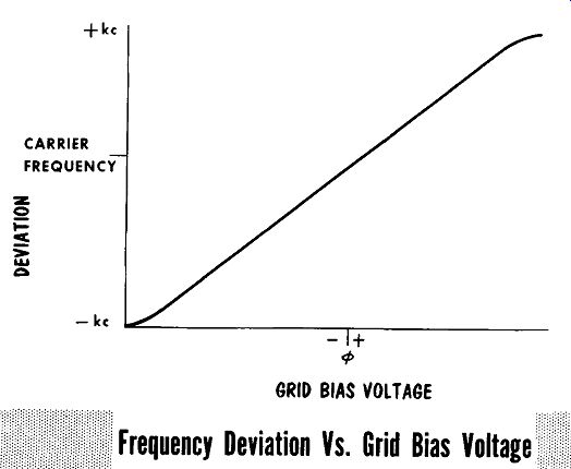
--
The antenna current is metered to check for any inadvertent amplitude modulation of the output signal. The output signal of an FM transmitter should be constant in amplitude; only the frequency should vary. The antenna current value readings should remain constant; if they fluctuate it is an indication that AM is present in the output signal. Most of the AM will be a result of nonlinearity in the reactance-tube modulator stage.
Another more remote possibility would be misalignment or narrow band width of the r-f amplifier stages.
Single-Sideband Circuit Checks
Many of the circuits encountered in single-sideband transmitters, such as r-f amplifiers and oscillators, have previously been discussed. Balanced modulators having tuned circuits or other circuit variables are checked by applying a 1000-cycle audio signal to the modulation input. The output of the modulator should consist of a double-sideband signal having a suppressed carrier (3000 khz) with a sideband signal at 2999 and 3001 khz. To check the output frequencies, a receiver set for CW reception is coupled
1 khz AUDIO OSCILLATOR
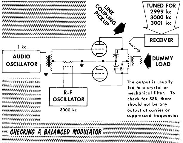
--------
The output is usually fed to a crystal or mechanical filter. To check for SSB, there should not be any output at carrier or suppressed frequencies
to the output as shown, and tuned to 3000 khz to check for zero output on the carrier frequency. The receiver should have equal amplitude signals at 2999 and 3001 khz.
The usual causes for unbalanced output, in which the carrier is not fully suppressed (aside from tuning adjustments) are defective tubes and tubes that are unmatched and have unequal gain. In transformer-coupled circuits, check for defective transformers; and in RC coupled circuits, check for changes in R and/or C values. Always check that equivalent points in the circuit have equivalent voltage values. For example: that both grids have the same input signal level, that both plates have the same voltage level, etc.
Balanced bridge modulators are usually hermetically sealed units. If a test indicates a defect such as an open diode, the entire unit will have to be replaced.
Phasing type circuits are prone to spurious emissions if not carefully adjusted for correct phasing. The arrangement shown checks for correct phasing. With a 1000-cycle audio signal applied to the modulation input, the output frequency should be that of the r-f carrier less (for lower sideband) the 1000-cycle input signal. The output viewed on an oscilloscope should appear as a CW signal with a constant frequency and constant amplitude. The presence of any ripple in the amplitude is a sign of spurious emission, and is due to poor or incorrect phasing, or improperly-adjusted balanced modulators. The deeper the ripple the poorer the suppression of the undesired spurious emissions. A ripple that is 10% of the peak-to-peak amplitude represents about 20 db of suppression, a ripple of 3.3% represents about 30 db, and a ripple of 1 % represents a desired value of 40 db of suppression.
CORRECT OUTPUT INCORRECT OUTPUT INDICATING POSSIBILITY OF SPURIOUS EMISSIONS OUTPUT FREQUENCY ON OSCILLOSCOPE
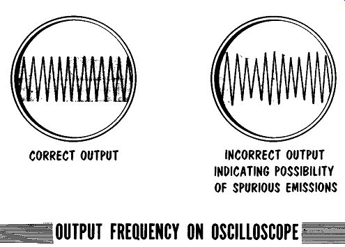
-----
Regardless of whether the single-sideband signal is developed by filter or phasing methods, the output must be applied to a linear amplifier, if increased output power is desired. Any presence of nonlinearity in the linear amplifier will result in undesired heterodyning, The resulting products of the sideband frequencies will cause additional undesired frequencies to the transmitted right about the carrier frequency or on what should be the suppressed carrier frequency. These undesired frequencies are known as splatter. The usual causes for nonlinearity are excessive grid drive to the input of the linear amplifier, too heavy or too light loading of the output, and poor or unregulated supply voltages fluctuating under load.
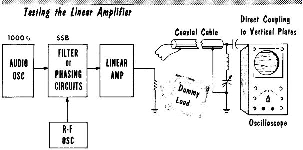
-------
To check the linear amplifier, its output is coupled to a dummy load. A portion of the output is picked off with a loop of two or three turns of wire, and fed through a coaxial cable to a tuned circuit at the input to an oscilloscope. The output of the tuned circuit is coupled directly to the vertical plates of the oscilloscope. The input from the r-f oscillator is set for about one-half the normal input level. The input from the audio oscillator is then set so that its output will result in the oscilloscope pattern resembling full modulation, Fig. A. Limiting caused by excessive drive to the linear amplifier or improper loading of the linear amplifier output is shown in Fig. B. Excessive grid bias bucks the correct input drive signal resulting in the pattern shown in Fig. C.
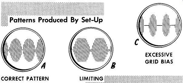
---------------- CORRECT PATTERN EXCESSIVE GRID BIAS
The driver stage converts the signal voltage of the speech amplifier stage to a power output capable of driving the modulator stage.
The high voltage present in the modulator stage is the same as that present in the r-f power amplifier stage, requiring the same precautionary measures.
With the plate voltage leading the grid voltage by 90 degrees, a tube can act as an inductor and appear to have the same reactance exhibited by an inductor.
Paralleling the inductor of an oscillator tank circuit with the reactance tube, permits varying the resonant frequency of the oscillator circuit by varying the voltage of the reactance tube. Modulating the grid with an audio signal provides an FM signal at the output of the oscillator.
Any change or fluctuation in the source voltages for the FM circuit would create changes in the output frequency. To prevent this all source voltages should be regulated.
Balanced modulators can be checked by application of a 1000-cycle audio signal. The output of a modulator using a 3000 -khz r-f oscillator should be zero on the carrier frequency, and equal-amplitude signals at 2999 and 3001 khz.
In balanced bridge modulators using hermetically sealed units, if a test indicates a defective diode, the entire unit has to be replaced.
Phasing-type, single-sideband circuits are prone to spurious emissions if not carefully adjusted for correct phasing.
Presence of ripple in the amplitude of the output signal is a sign of spurious emission. The deeper the amplitude ripple, the poorer the suppression.
A ripple of 10% of the peak-to-peak amplitude represents about 20 db of suppression. The desired value of suppression is 40 db, about 1 % ripple.
REVIEW QUESTIONS
1. Why are pentode-type power-amplifier tubes often used in a triode connection in driver amplifiers?
2. What types of tubes are usually used in the modulator stage?
3. What would be the indication of shorted, transient suppression capacitor across the transformer winding?
4. Describe the method used to check the linearity of the modulation in a reactance tube FM circuit?
5. How do we check the output of an FM transmitter for undesired amplitude modulation?
6. Describe what is meant by checking that equivalent points have equivalent values in a balanced modulator.
7. With a 1000-cycle audio signal applied to a phasing circuit, what should the output and the amplitude of the output appear as on an oscilloscope?
8. What are the usual causes for nonlinearity in a linear amplifier?
9. Describe the method used to check a linear amplifier.