AMAZON multi-meters discounts AMAZON oscilloscope discounts
THE function of the mixer tube has been mentioned briefly in the discussion of signal tracing in local oscillator circuits of superheterodyne receivers. This tube serves to combine or mix the broadcast signal with the locally generated heterodyning signal. As a result of the mixing process, a frequency-changing action takes place whereby a new frequency is formed, representing the difference between the frequency produced by the local oscillator and that of the incoming broadcast signal.
The mixer tube is also identified by other names. Because of its frequency-changing action, it is sometimes called a frequency changer. Since it operates as a detector for the incoming broad cast signal, which is heterodyned by the set oscillator, it is occasionally ref erred to as a heterodyne detector. Other terms applied to it are first detector, converter, translator, modulator and even demodulator. Each of these terms refers to some phase of mixer operation.
Any tube which can serve as a rectifier or detector of radio frequency signals can act as a mixer. In fact, even a crystal detector or other rectifying device could be used for the purpose.
In actual practice, though, only tubes are used and the tube types are so chosen and operated that amplification is combined with mixing. As there is no known method of obtaining amplification when using diodes or other two-element rectifiers as mixers, and for other reasons, they are not used in broadcast receivers.
Earlier receivers employed triodes or tetrodes as mixers, while more recent sets use pentodes or pentagrid converters. Modern all-wave receivers, when a separate tube is used as the local oscillator, usually employ a hexode such as the 6L7. No matter which type of tube is employed, the mixing action is essentially the same and while it is unnecessary to know precisely what takes place during the mixing process in order to apply signal tracing successfully to such circuits, some knowledge of the manner in which the mixer functions will be of value in analyzing mixer faults.
Mixer Action
When two signals which differ in frequency are fed simultaneously into a detector tube input circuit, both signals will appear in the output circuit. At some instants, these two signal voltages will be in phase and the resulting output signal voltages will add; at other instants they will be out of phase and therefore will oppose each other. This aiding and opposing effect results in beat frequencies which correspond to the sum and difference of the original frequencies introduced into the input circuit of the mixer. Since harmonics are also present, a number of beat frequencies normally are formed in the mixer output circuit. These are usually small in magnitude in comparison with beat frequencies formed from the fundamental frequencies. In most super heterodyne receivers, the beat frequency which is selected for amplification by the i-f amplifier is that which represents the difference in frequency between the two original fundamental frequencies. When the i-f transformer primary in the plate circuit of the mixer tube is tuned to resonance with this difference frequency, the signal voltage across this winding is greatest for this frequency and therefore harmonics and undesired beats are further minimized.
Tubes which are used as mixers usually operate as linear detectors, that is, the rectified output signal is directly proportional to the amplitude of the incoming broadcast signal. This means, if we tune to one broadcast signal and get a given output i-f voltage, another broadcast signal of twice the voltage at the mixer input will give twice the i-f voltage at the mixer output, when avc action is absent. For minimum distortion when this type of detector is used as a mixer, the heterodyning oscillator signal voltage must be much higher than the broadcast signal voltage at the mixer input grid.
For triodes, tetrodes or pentodes, linear detection action for mixer operation is usually secured by using a high value of cathode bias. Accordingly, the grid is highly negative with respect to the cathode and the plate current is low, near cut-off. This method of operation permits a high oscillator voltage to be introduced in the input cathode or grid circuit without causing the control grid to draw current and thus load the input circuit as well as affect detector action. In more modern mixers, the local oscillator signal is fed to a grid which is electrostatically shielded from the input grid and therefore reaction of the oscillator signal on the mixer input circuit is usually negligible. Hence, for such tubes, a high cathode bias is unnecessary and is not used because it would result in reduced efficiency.
Gain in the Mixer
When a mixer tube is operating efficiently, the i-f signal voltage in the mixer output circuit is greater than the broadcast signal voltage in its input circuit. This gain resulting from the frequency-changing or conversion action in the mixer tube is called the conversion gain, or the translation gain. More precisely, this may be expressed as the ratio of the i-f voltage across the mixer output load to the r-f signal voltage applied to the mixer input grid. Conversion gain may be accurately measured with a tuned vacuum-tube voltmeter, of uniformly high sensitivity at both the radio and intermediate frequencies, by checking the i-f signal voltage at the mixer plate when an r-f signal is present in the input grid circuit. The r-f signal level is then measured and the ratio of the i-f signal voltage to that of the r-f signal voltage gives the conversion gain. This is greatest when the alignment is exact.
It is not necessary to know the absolute value of the signal voltages present at each point to determine the gain, but it is necessary to be able to determine the relative intensity of each signal.
For example, let us assume that the i-f signal at the mixer plate gives a reading of 100 on our measuring device while the r-f signal gives a reading of 10. The ratio is 100 to 10 or 10 to 1 and the conversion gain is therefore 10. It does not matter whether the readings are in microvolts or millivolts as long as the measuring device is properly calibrated and equally sensitive at each frequency, and the signal voltage applied is not so great as to over load the mixer. It is also possible to measure the conversion gain with a signal generator which is equipped with an accurately calibrated attenuator. An i-f signal of the same frequency as that to which the i-f amplifier is tuned is fed to the input grid of the first i-f tube.
A modulated signal is used so that an output meter may be connected at some point in the audio system and its reading noted for the signal passing through the i-f and audio systems.
The signal generator is then connected to the mixer input circuit and a modulated r-f signal is fed into the mixer. The receiver oscillator is tuned to the frequency required to mix with this r-f signal and produce a maximum response as indicated by the receiver output-meter reading. If conversion gain is being secured in the mixer, the output-meter reading should be greater than it was for the i-f signal test. Then the signal-generator attenuator should be readjusted until the receiver output meter reads the same as it did when the i-f signal was fed to the i-f tube. The conversion gain is the ratio between the two readings of the signal generator attenuator. If the setting for the i-f signal is 50 and that for the r-f signal is 5, the ratio is 10.
This method of injecting a signal from grid to grid rather than from grid to plate does not take into account any gain or loss which may take place in the i-f transformer which couples the plate of the mixer tube to the grid of the first i-f tube. Usually there is a slight loss in the transformer so that the actual conversion gain will be a trifle higher than indicated by the above test.
The reason that the signal generator is not connected directly to the plate of the mixer when making the i-f measurement is be cause to do so would load the i-f transformer primary excessively and would therefore give misleading results.
In typical modern broadcast receivers, the conversion gain ranges from about 30 to 60 when no avc action is present. The avc action reduces gain to a degree dependent upon its effective ness in the receiver, but in any event there will usually be some conversion gain.
The Triode Mixer
Now let us consider a simple triode mixer circuit from the signal-tracing standpoint. In Fig. 6-1, let us assume that the schematic represents a portion of a typical receiver which is connected to an antenna and is functioning normally. Assume that the set is tuned to an incoming broadcast signal on 600 khz. The set oscillator is feeding a 775 -khz heterodyning signal into the mixer input circuit due to inductive coupling between the oscillator coil L4 and the coupling coil L3 which is in series with the mixer tuned circuit, L2 and C1.
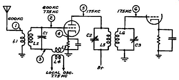
Fig. 6-1. A triode mixer circuit showing the distribution of signals at the
various points in the circuit.
Before proceeding farther, let us examine this circuit with regard to the signals present in each portion of the circuit. At point 1, which corresponds to the antenna post on a typical receiver, we find two principal signals in which we are interested. One of these is the broadcast signal of 600 khz which is picked up by the antenna, another is the local oscillator signal of 775 khz which is being introduced into the grid circuit of the mixer by means of the inductive coupling between L3 and L4. While the antenna coil is not directly coupled either to L3 or L4, some of the 775 -khz signal will appear in the antenna circuit due to the coupling between L1 and L2. While L2 is tuned to resonance with the in coming broadcast signal at 600 khz, the tuning is not sufficiently sharp to reduce its impedance to zero at the frequency of the 775 -khz signal which is in series with it. Therefore there is a 775 -khz signal voltage drop across L2, and because of its coupling to L1, this 775 -khz signal appears in the antenna circuit and is radiated in the same manner as any broadcast carrier. Consequently, this type of coupling causes interference with the operation of other receivers and has been used but little.
The signal voltages in the mixer input circuits are shown at points 2 and 3 in the diagram. At point 2, the 600 -khz signal and 775 -khz signal will be found; likewise at point 3. However, the 600 -khz signal will be much stronger at point 2 than at point 3 because L2 is tuned to resonance with this frequency and consequently offers a high impedance to it. Due to this high impedance, there is a large voltage drop across L2 and the 600 -khz signal voltage is a maximum at point 2. On the other hand, the oscillator coupling coil L3offers a low impedance both to the oscillator voltage and to that of the incoming signal. The 600-khz signal will therefore be much lower in voltage at point 3 than at point 2. The oscillator signal voltage will be greatest at point 3, and since the oscillator signal voltage is normally much higher than that of any broadcast signal at this point, it will be difficult to check the presence of the 600-khz signal at this point due to the blanketing effect of the strong oscillator signal. At point 2, though, both signals can be checked.
We have mentioned that several frequencies are present in the mixer plate circuit. In the circuit of Fig. 6-1, we find that the principal frequencies which are present at point 5, the mixer plate, are the 775-khz heterodyning oscillator signal, the 600 -khz broadcast signal, and the 175-khz i-f signal, which represents the frequency difference between the 775-khz local oscillator signal and that of the 600-khz broadcast signal. We also find a weak 1375-khz signal, which represents the sum of the 775-khz and the 600-khz signals. Since the i-f amplifier is designed to operate at 175 khz, the i-f transformers are tuned to this frequency and therefore the primary circuit of the first i-f transformer, shown as L5 and CS, present a maximum impedance to this frequency. Thus the i-f signal voltage at 175 -khz should be far higher than any of the other signal voltages present at this point. At point 6, the grid of the first i-f tube, undesired frequencies will be further filtered out so that little but the 175 -khz i-f signal will be applied to the grid of the first i-f amplifier tube.
In Fig. 6-2, the mixer action and circuit are similar to that shown in Fig. 6-1, but the heterodyning oscillator voltage is in series with the cathode and ground rather than with the grid and ground. This is a more commonly used type of oscillator frequency coupling when the older types of tubes are used as mixers.
In this circuit, the mixer grid voltage with respect to ground varies only at the incoming broadcast signal frequency and not at oscillator frequency as was the case shown in the circuit, Fig. 6-1.
Accordingly, there will be no 1065-khz signal present at point 2, except that introduced by coupling within the tube and stray coupling in the circuit. Both these effects may combine to produce a slight 1065-khz signal at this point, but it will be negligible in comparison with that which will be found at the corresponding point in the circuit of Fig. 6-1. At point 3, the mixer cathode, the oscillator signal will predominate to a greater degree over the r-f signal for the same reason. We find then, in this circuit, that the …
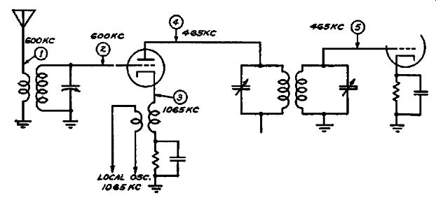
Fig. 6-2. A triode mixer circuit in which the oscillator signal is fed into
the cathode circuit.
… cathode potential is varied at the heterodyning oscillator frequency while the grid potential is varied at the broadcast signal frequency, both with respect to ground. However, the operation of any amplifier tube is based on the variation of the grid potential with respect to cathode and not to ground. With this in mind, we can see that the grid voltage is varied at both frequencies and consequently the plate voltage is varied in the same manner. Since the tube is biased as a plate detector, rectification occurs and the intermediate frequency is formed.
In Fig. 6-2, the radiation of the oscillator signal into the antenna system will be reduced for the reasons given in the preceding paragraph, and also because the wider difference between the frequency of the oscillator and that of the tuned input circuit will tend to reduce the small oscillator voltage which appears across the tuned input circuits. In the plate circuit, the original frequencies as well as the sum and difference components will be found, but again the undesired frequencies will be much lower in voltage than the desired 465-ke signal when the i-f transformer is tuned to that frequency.
The Tetrode Mixer In Fig. 6-3, another method of coupling the oscillator signal to the mixer is shown. This is used in the Franklin Model 94 receiver. As shown, the screen grid of the mixer is directly coupled …
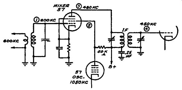
Fig. 6-3. A pentode is used in the mixer stage and the oscillator signal is
fed into the mixer circuit by connecting the screen to the plate of the oscillator
tube.
… to the plate of the local oscillator tube. The oscillator signal voltage developed across the 50,000-ohm load resistor in the oscillator plate circuit varies the screen potential at the oscillator frequency. That is, on the positive half of the oscillator signal wave, the screen voltage of the mixer is increased while on the negative half the voltage decreases. This increase and decrease of voltage causes a corresponding increase and decrease of plate current, hence modulation of the plate current at the oscillator frequency results. This is one form of electronic coupling.
Any other tube element whose potential affects electron flow could be used for the same purpose. At the mixer grid, point 1, we should find the broadcast signal, and at point f, a strong oscillator signal voltage should be present. In this form of modulation, the oscillator signal is necessarily considerably higher than when the signal is introduced in the grid or cathode circuits. The reason for this is that a relatively small oscillator signal on the mixer input grid will cause a greater change in the plate voltage than the same signal on another grid which has less controlling effect on the plate voltage. We are discussing, of course, the instantaneous variations of plate voltage caused by an r-f signal and not d-c voltages.
Other signals normally found at the plate of the mixer will also appear at point 2. Since the screen load is a resistor rather than a tuned circuit, the undesired frequencies at point 2 will be stronger than at the plate, point 3. This is because of the selectivity of the plate circuit, which is tuned to select the intermediate frequency; the resistor in the screen circuit, on the contrary, is not selective. The relative strengths of the undesired signals in the plate circuit are similar to those given in previous examples. At point 4, all undesired frequencies should be reduced to a negligible value, because of the additional tuned-circuit selectivity of the i-f transformer secondary.
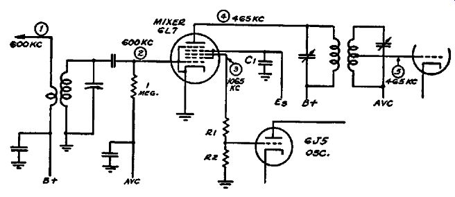
Fig. 6-4. The mixer circuit used in the G.E. Model F-135. The signal distribution
is shown in the figure.
Modem Mixer Circuits
In Fig. 6-4, the mixer circuit of a typical modern broadcast receiver, the General Electric Model F-135, is shown. The signal distribution throughout this circuit is indicated on the schematic.
At point 1, we find only the incoming broadcast signal, assumed to be 600 khz, which is being fed directly into the circuit. Any oscillator signal voltage which may appear will be due to stray pickup by the test probe and incidental coupling due to imperfect shielding of the oscillator coil itself. Such effects are negligible compared with those which occur in the older types of mixers which we have just described.
At point S, the r-f signal grid, we shall find the maximum 600 -khz signal with the 1065 -khz heterodyning oscillator signal reduced to negligible proportions because of the shielding effect of the second and fourth grids which surround the oscillator signal grid at point 3. These extra grids, which are by-passed to ground by C1, prevent the formation of excessive oscillator voltage at point S and thus eliminate the need for high negative biasing of the control grid to remove the possibility of grid current. Operating the tube at its normal control-grid bias increases its conversion gain and consequently its efficiency as a mixer. The control grid bias in this receiver is furnished by a bias diode which forms a portion of the avc system.
The oscillator signal grid of the 6L7, at point 3, in Fig. 6-4, receives a negative bias due to its coupling to the 6J5 local oscillator control grid. As mentioned in the discussion of signal tracing in oscillator circuits, oscillation causes a negative, pulsating d-c voltage to appear across the oscillator grid leak. The direct connection through resistor R1 applies a large portion of the negative biasing voltage in the oscillator circuit to the third grid of the 6L7. In mixing circuits in which electronic coupling is employed, the oscillator signal voltage should be sufficiently high to provide complete modulation of the plate current. In most commercial broadcast receivers, our concern is that this peak signal voltage be not less than 12 volts when the 6L7 voltage is 100 and not less than 18 volts when the 6L7 screen voltage is 150. If no vacuum-tube voltmeter, which measures peak r-f signal voltages, is at hand, the voltage may be determined to a degree sufficiently accurate for service purposes by measuring the d-c voltage at point S. For a 20,000-ohm grid leak R2, the rectification efficiency is of the order of 0.7, which means that a d-c reading at this point of -8.4 volts will indicate an oscillator peak voltage of 12. For a 50,000-ohm grid leak, the rectification efficiency is somewhat higher, so the resulting d-c reading should also be some what greater than -8.4. In any event, this voltage is normally considerably greater than the minimum value specified. When the maximum oscillator voltage is applied to the mixer, the volt meter used for such measurements should have an input resistance of at least 10 megohms and some means should be incorporated in its design to make certain that no appreciable amount of oscillator signal voltage at point 3 is by-passed by the voltmeter leads when the instrument is connected to the circuit.
In Fig. 6-5, we have another example of electronic coupling using a 6L7 mixer. This diagram shows the oscillator and mixer …
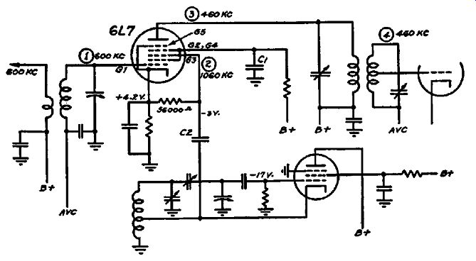
FIG. 6-5. The mixer circuit used in the RCA Model C15-3. The relative signal
strengths is discussed in the text.
… circuits of the RCA Model C15-3. This receiver was checked with a Rider Chanalyst to determine the relative strength of the various signals in the mixer circuit when the receiver was performing normally.
In making this test, a 600-khz signal was fed to the antenna and the receiver was tuned to resonance with it. The test probe was connected to G1 (point 1) and the signal level was found to be 7.5 millivolts. The probe was then moved to G2 (Point 2) and the 600-khz signal was noted but it was necessary to increase the signal at G1 eight times to provide a 7.5-millivolt signal at G3.
Therefore, the r-f signal appearing at G3 is only 1/5 th that at G1.
At the mixer plate (point 3), the 600 -khz signal was found to 1.2 times the signal voltage at G1 ... a 20-percent gain. It is important for us to know this, since this measurement shows that the signal level at the mixer plate is sufficiently high, even though the circuit is tuned to 460 khz instead of 600 khz, so that aligning and padding operations in the r-f circuit may be carried on with the test probe at point 3. In this manner, any slight detuning effects, which might otherwise interfere with aligning operations, may be avoided.
Some of the 600-ke signal voltage also appears when the probe is connected to G4, which is already by-passed to ground. Normally this signal is very weak, about 1/30 th of that at G1, and is due more to stray pickup by the probe rather than to the presence of a signal voltage at this point. If the shield grids, G2 and G4, are not by-passed, however, the signal level increases greatly.
By actual measurement, when C1 is open-circuited, the 600 -khz signal at G2 and G4 is 5 times that at G1. So by signal tracing, we can check condensers for proper functioning in this circuit.
In this receiver, only a portion of the oscillator voltage is fed to the third grid of the 6L7 since the coupling condenser C2 connects to a tap well down on the oscillator coil. This is frequently done in all-wave receivers when the range extends to ultra-high frequency bands and assures more uniform oscillator operation on such bands at a slight sacrifice of conversion gain in the mixer tube. The heterodyning oscillator signal is applied to G3 which returns to cathode through a 56,000-ohm resistor. If no oscillator voltage were present, G3 would have the same potential as the mixer cathode, which is plus 4.2 volts with respect to ground.
When the oscillator signal is applied to G3, its intensity is sufficiently great to change this positive voltage to -3 volts. This pulsating d-c voltage results from rectification of the oscillator signal voltage by G3. Since the potential of G3 is thus changed from +4.2 volts to -3 volts, the total change is 7.2 volts so the actual d-c voltage of this grid with respect to cathode is -7.2 volts. The peak value of the oscillator voltage applied to this grid is approximately 6.3 volts. The measured conversion gain under these conditions was found to be 20, which is somewhat less than could be obtained with a higher oscillator voltage, though still high. The advantages derived compensate for the slight drop in conversion gain resulting from the use of less than normal oscillator signal voltage.
The oscillator signal voltage at GS is 600 times as great as the 600-khz signal in the mixer input circuit, thus fulfilling the requirements stated earlier in this section that the oscillator voltage should be large in comparison with the incoming signal. While this voltage remains constant- as the incoming signal varies, avc action in the receiver tends to keep the ratio of oscillator voltage to signal voltage high.
This 1060-khz oscillator signal also appears at the plate of the mixer, point 3 in Fig. 6-5, and its intensity at this point is 100 times as great as the 600-khz signal at this point. Therefore the oscillator frequency can be checked at this point, thus avoiding any detuning of the oscillator circuit through the effect of test leads on the oscillator.
The 460-khz signal, representing the frequency difference between the incoming r-f and local oscillator signals, is 20 times as great at the mixer plate as the 600-khz signal at the mixer input grid, G1. This ratio represents the conversion gain of the mixer, which is therefore 20. The 460 -khz signal is also detectable at G3, but its voltage is less than 1/10th that of the 600-khz signal at G1.
This is because the circuit at G3 has very low impedance to the 460 -khz signal. The 460 -khz signal was not detected at G1 or G2. The 1660 -khz signal, representing the sum of the 600-khz and the 1060-khz signals is present both at G3 and at the mixer plate.
Its strength at G3 is 1/25th that of the incoming 600-khz signal at G1 and at the mixer plate it is ½th that of the 600-khz signal at G1. This 1660 -khz signal is weak at the mixer plate because the i-f transformer is tuned to 460 -khz and therefore is far off resonance for 1660 -khz.
The foregoing tests apply, of course, only to this particular receiver and to the results secured at a single point in its tuning range, 600 khz. If a 1400-khz signal is applied to G1, this signal will be only ¼th as strong at the mixer plate. But this will serve to give an idea of the relative magnitude of various signal frequencies so that conditions which are abnormal may be more readily recognized.
Mixer Circuit Troubles
Any fault which may occur in a mixer circuit will affect its output i-f signal. One of the most common troubles, for instance, is circuit misalignment. If the heterodyning oscillator signal is off frequency when the receiver r-f system is tuned to an incoming signal, then the i-f signal will be off frequency by the same amount. If the i-f transformer is also tuned off frequency to resonate with the incorrect intermediate frequency produced by the local oscillator, then the conversion gain at this frequency will be normal but the oscillator will not track properly. By checking all signal frequencies at the plate of the mixer, any circuit mis alignment is promptly revealed and the faulty circuit is definitely identified.
In the circuit of Fig. 6-5, for instance, the required i-f is 460 khz. Our first step is to feed a signal of known frequency to the receiver, and with the probe of our test instrument connected to the mixer plate, to tune in this r-f signal until a maximum indication is secured when the test instrument is tuned to the same frequency. This test should be made with the avc system, if used in the receiver, rendered inoperative either by grounding the oscillator grid or removing the avc tube. If the pointer on the receiver dial does not indicate the proper frequency, or if readjusting the r-f trimmers produces a stronger signal, the r-f system is out of alignment.
If the r-f system is properly aligned, then the oscillator frequency may be checked in the same manner, without readjusting the gang tuning condenser. The oscillator frequency should be 460 khz higher in frequency than the incoming r-f signal. If not, then the i-f signal will be higher or lower in frequency by the same amount, and the oscillator frequency will have to be re adjusted.
The i-f signal now may be checked. If it is found to be weak, then the adjustment of the i-f transformer primary trimmer may be checked by moving the test probe to point 4, or to any other point in the i-f system where the connection of the test probe will not affect the first i-f transformer primary tuning circuit, and adjusting this trimmer for maximum i-f signal output. A defective transformer primary will not align sharply.
If all mixer circuits are in proper alignment and there is little or no conversion gain, the tube may be checked independently in a tube checker, or by substituting another in the circuit. If necessary, this may be followed by voltage tests and resistance measurements until the exact component at fault is located.
Distortion in mixer circuits employing triodes, tetrodes, or pentodes may occur as a result of incorrect tube voltages, defective tubes or excessive oscillator signal voltage. Any of these conditions will decrease the conversion gain, thus localizing the trouble. Distortion may be directly examined by checking the signal with phones or an oscillograph connected to the output of the test instrument when the test probe is at the mixer plate.
SIGNAL TRACING IN CONVERTER CIRCUITS
When the functions of the oscillator and mixer are combined within a single tube, such a tube is now generally known as a converter. Occasionally this term is also applied to tubes which are ordinarily used as combination oscillator-mixers, such as the
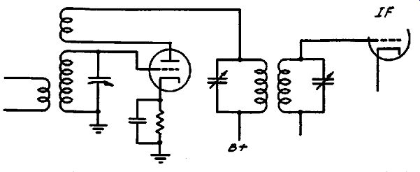
FIG. 6-6. An autodyne mixer circuit. The input circuit is tuned to the oscillator
frequency so that it is somewhat de tuned for the incoming signal.
6A7, when such tubes are employed as simple mixers. In the converter circuits we are going to discuss, we refer to those in which both operations are performed by the same tube. Any tube which can be made to oscillate can be used as a converter, though all modem receivers have discarded the simple triode for this purpose. In all converter circuits, the incoming signal modulates the oscillator-frequency current produced within the tube and thereby forms the required intermediate frequency as described in the pre ceding section.
The simplest form of converter is called the autodyne mixer.
A typical circuit of this type is shown in Fig. 6-6. The incoming broadcast signal is impressed upon a triode oscillator grid circuit, which is tuned to the oscillator frequency. The intermediate frequency voltage is developed across the primary of the tuned i-f transformer in the plate circuit. Since the triode is tuned to the oscillator frequency, and only a single tuned mixer input circuit is used, it is detuned for the incoming broadcast signal.
Therefore, the maximum signal voltage is not s0cured with this type of autodyne mixer and inefficient operation results. Variations of this autodyne circuit in which the oscillating circuit is tuned to one-half the desired oscillator frequency, so that the second harmonic produces the required beat, were used in later receivers and this eliminated one of the objections to the simple autodyne, in that the input circuit could be separately tuned to the broadcast signal. More modern circuits using tetrodes or pentodes, accomplish the same results without using the oscillator second harmonic.
A Tetrode Autodyne Converter
An example of a tetrode autodyne converter is shown in Fig. 6-7. Oscillation is maintained by feedback between L2 and L3 and the frequency of oscillation is controlled by tuning L4. C2 acts as the oscillator tuning condenser, CS as the oscillator pad der and C4 as the oscillator trimmer. The converter input circuit is tuned to the incoming broadcast signal frequency by C1.
In tracing the signals in this circuit, we shall find the broadcast signal to be a maximum at point 1 when the converter input circuit L1, C1 is tuned to resonance with it. Since the required intermediate frequency is 262 khz, the oscillator frequency should be 262 khz higher than that of the broadcast signal. Though the converter input circuit is grounded and detuned from the oscillator frequency by 262 khz, the magnitude of the oscillator signal voltage is so much greater than that of the broadcast signal that coupling within the tube and radiation from the oscillator tuning condenser and coil will produce an appreciable oscillator signal voltage on the converter input grid.
At the converter plate, point 1, a strong oscillator signal voltage will be present because in this circuit the plate forms a portion of the oscillating circuit. The oscillator signal will also be strong at points S, 4 and 5 if testing at these points is required .
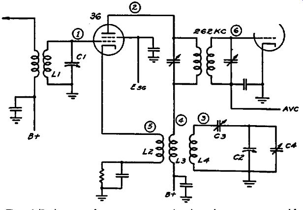
Fig. 6-7. An autodyne converter circuit using a screen grid tube. The local
oscillator frequency is controlled by the oscillator section of the tuning
condenser C2.
The general procedure in testing any circuits of the converter type follows the same routine as that described for separate oscillator and mixer circuits, but it will be found that circuits of the autodyne type usually will give evidence of reaction of one circuit upon another. When the r-f circuit is precisely aligned, changing the oscillator trimmer and padder adjustments will affect not only the tuning of the oscillator circuit but also that of the converter input circuit. This should be taken into account when aligning by making certain that the output signal voltage is greatest when the adjustments are completed.
An application of a pentode as a converter of the autodyne type is shown in Fig. 6-8. This is the circuit employed in the Majestic 400-A. The oscillator tuning is done by resonating the suppressor circuit to the desired oscillator frequency. The input circuit to the converter is tuned to the frequency of the broadcast signal.
Though this circuit is rather unusual in design, testing by signal tracing is done in the same manner as with any other converter circuit. The r-f signal may be checked at point 1, the oscillator signal at point 2 or point 3 and the i-f signal at point 3.
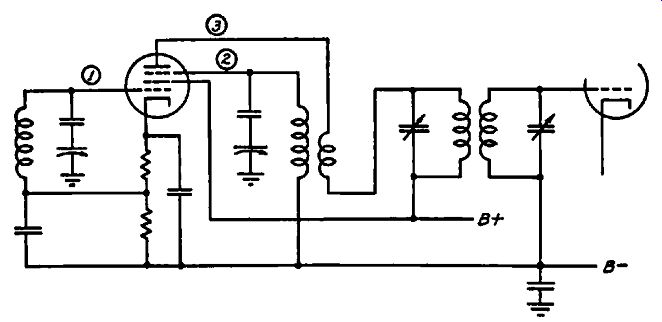
Fig. 6-8. The converter circuit used in the Majestic Model 400-A. The suppressor
circuit is tuned to the desired oscillator frequency.
Pentagrid Converters
Pentagrid converters are the most widely used of all types in most modern receivers. Of these, the 6A7 or its equivalent is most often employed and a typical circuit for this converter is shown in Fig. 6-9. This type of tube has five grids, whence the name pentagrid is derived. The first grid, nearest the cathode, acts as the oscillator grid while the second serves as the oscillator anode. The third grid forms a screen around the fourth, or signal grid to minimize interaction between the oscillator and r-f signal sections the tube. The fifth grid serves as a screen grid and provides a high plate resistance so that a high plate load may be efficiently utilized. The third and fifth grids are connected to each other within the tube.
In operation, oscillation in the section of the tube composed of the cathode and the first two grids causes the electron flow to the plate to vary at the oscillation frequency. Since these electrons must flow through all five grids, they will be affected by signal voltages which happen to vary any of these grid voltages.
Fig. 6-9. A typical pentagrid converter circuit. The incoming signal is applied to the fourth grid and the oscillator frequency is controlled by tuning the circuit connected to the second grid.
The incoming r-f signal is applied to the fourth grid, and the varying potentials resulting from the r-f signal voltages on this grid modulate the electron flow which is already varying at the oscillator frequency. This causes the plate current to vary, not only at the oscillator and signal frequencies, but also at the difference frequency which is the required intermediate frequency when the circuits are properly adjusted.
Signal tracing in pentagrid circuits follows the same general procedure as that described for separate oscillators and mixers.
We check the conversion gain by measuring the i-f signal voltage at the pentagrid plate and the r-f signal voltage at the input grid, the fourth grid from the cathode. The ratio of these two voltages is the conversion gain, which varies from about 10 to 40 in broad cast receivers when the avc system is inoperative. When avc action is present, the conversion gain is reduced to about ¼ th of these figures. Exact gain measurements are seldom necessary in servicing procedure; usually the mere fact that there is a conversion gain, rather than a loss, in the converter tube is sufficient to eliminate this portion of the receiver as a cause of poor operation.
The pentagrid converter circuit shown in Fig. 6-9 is that used in the RCA Models 85E and Ul02E; it is representative of a large number of designs. The r-f signal is checked at point 1, the oscillator signal at point 2, 3, 4 or 5, the i-f signal at points 5 and 6.
At point 3, the rectified oscillator voltage across the oscillator grid leak can be measured. This voltage varies widely in different receivers, usually ranging from -3 to -20 volts with respect to ground. If the oscillator section is inoperative, this voltage will be zero or some positive value, depending upon the circuit used.
However, regardless of the circuit used, a measurement of the voltage which is made with the test leads connected to each terminal of the oscillator grid leak, rather than to grid and ground, will tell the story. Then the grid always will be negative when the oscillator is functioning.
In using a test oscillator for signal tracing in pentagrid circuits, the converter may be separately checked by feeding a modulated signal at the intermediate frequency to point 1 in Fig. 6-9. The 6A7 will then act as an i-f amplifier and the output signal level in some portion of the a-f system may be checked with an output meter. The test oscillator then may be connected to point 6, the first i-f control grid, and the test oscillator attenuator readjusted to give the same output-meter reading. The ratio of the test oscillator voltage outputs at the two settings of the attenuator show the gain of the converter tube at the intermediate frequency, less any loss or gain in the i-f transformer. This is not the same as the conversion gain, which is obtained in the same manner except that an r-f signal is fed to the mixer instead of an i-f signal.
The oscillator section of the pentagrid converter is checked by feeding the test oscillator signal to point 3 in Fig. 6-9. The receiver should be tuned to a broadcast signal or any other signal the frequency of which is definitely known. The test oscillator should be adjusted to produce a frequency equal to that of the incoming r-f signal plus that of the intermediate frequency. Thus, if the receiver is tuned to a 600 -khz signal, and the i.f. is 460 khz, the test oscillator should be set at 1060 khz. The attenuator should be adjusted for maximum output; even so, the maximum voltage delivered by the test oscillator will be far less than that supplied by the pentagrid converter oscillator section when it is working properly. However, this substitution method may be used to localize faults in the pentagrid converter when no other suitable equipment is on hand.
Summary
The general remarks regarding trouble-shooting in oscillators and mixers are equally applicable to pentagrid converters. In some receivers, avc action causes the frequency of the oscillator section of the converter to change. This is particularly trouble some at the high-frequency end of the tuning range. When a strong signal is being tuned in, especially on short-wave bands, the point of resonance is not the same when the receiver is tuned from a higher-frequency point on the dial as it is when the tuning is approached from a lower-frequency point. Often it is necessary to tune back and forth around the normal point of resonance before the station can be tuned in for maximum response. Then when the receiver is tuned s. little beyond this point, the signal may drop out completely and retuning in the same manner may have to be repeated. This annoying condition occurs because a strong signal creates a high avc voltage and the high avc voltage increases the bias on the converter _input grid, thereby decreasing the mutual conductance of the converter tube. This changes the tube load on the oscillator tuning circuit and causes a frequency shift which is particularly large when the shunt capacity of the tuning system is a minimum, as it is at the high-frequency end of the tuning range.
The correction of this trouble requires some modification of the avc so that less control voltage is applied to the converter grid or reduction of the signal strength of the off ending station by changing the antenna location or otherwise decreasing the signal pickup. Triode-hexode converters, such as the 6K8, are substantially free from this trouble due to modifications in the design of the tube, but triode-heptodes, such as the 6J8, will be subject to this trouble unless precautions were taken in the design of the receiver to minimize such effects. Signal tracing in the two latter types of converter tubes follows along the same lines as for penta grid types.