AMAZON multi-meters discounts AMAZON oscilloscope discounts
Transistors are ideally suited for auto radios. The low-voltage DC power supply (car battery) is already present, and because transistor radios draw less current than tube sets, the drain on the battery is kept to a minimum.
Transistors did not replace tubes in these radios all at once.
Instead, it was a gradual process. The part-tube, part-transistor radios were called "hybrid" sets. The power output tube was first replaced by a power transistor, and millions of these 4-tube, 1 transistor radios were produced in the late 1950's and early 1960's. Actually, three engineering achievements teamed together to provide a perfect blend between tubes and transistors: (1) the development of the transistor itself, (2) the change from a 6-volt to a 12-volt automobile ignition system, and (3) the design of a vacuum tube which required only 12-volts on the plate for efficient operation.
With these developments, it was possible to eliminate the high voltage power supply and its troublesome and bulky components--rectifier tube, vibrator, and power transformer.
The cost saving permitted the use of a power transistor, even though transistors were much more expensive than tubes at that time. Then, in 1962, more efficient and moderately priced RF transistors were available, so most auto radios became all transistor sets. By 1963, practically no tube models were being produced. Troubleshooting the transistor car radio follows the same principles learned previously. The problem is first localized to one section of the radio, then certain voltages are read to pinpoint the defect.
SCHEMATIC FAMILIARIZATION
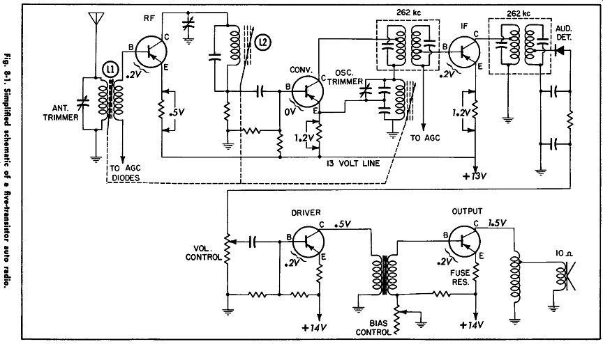
Fig. 8-1.
A typical auto radio diagram is shown in Fig. 8-1. For study purposes, some of the bypass capacitors have been eliminated, but a complete auto radio schematic will be shown later.
What do you notice about this schematic? First of all, it is very similar to the first transistor radio schematic studied (see Section 3). One additional stage-the RF stage-has been added, but otherwise, the auto radio contains the same number and type of stages.
There is one other difference in the way the car radio is tuned. Notice the three dotted lines and arrows shown with coils L1, L2, and L3. They represent tuning cores, or slugs, which are located inside each coil. The slugs are all mounted on a common bar, which moves as the radio is tuned. This changes the inductance of the coils and tunes the auto radio.
Formerly, tuning was done by variable capacitors (as in home and portable radios) but, due to vibrations experienced in automobiles, the more stable inductive tuning has been practically universally adopted in auto radios. Small trimmer ( or padder) capacitors are connected across each coil for alignment purposes.

Fig. 8-2. Block diagram of the receiver in Fig. 8-1.
Again, the radio should be mentally divided into blocks (Fig. 8-2) for troubleshooting purposes. Each block represents a transistor or diode and its associated components (resistors, coils, and capacitors). What else can we determine about this radio by a quick glance at its schematic?
1. That the radio uses all PNP transistors.
2. That all transistors are of the germanium type (germanium amplifiers require .2 volt bias, silicon amplifiers 0.6 volt, except converters).
3. That the IF frequency is 262 khz.
4. That the audio stages are transformer coupled.
5. That the radio requires an 8 to 10-ohm speaker.
6. That the radio operates on a car battery voltage of 12 volts (14 volts with generator running).
7. That the RF and IF stages are controlled by AGC ( automatic gain control) .
8. We can also see how to check the conduction ( current flow) of each transistor.
Since Step 8 is the most important test available to the troubleshooter (along with bias), it will be stressed as we get into pinpointing the troubles. But first, let's turn this radio on and see if we can localize the trouble with our listening checks and expert personal observation.
TRACKING DOWN THE TROUBLES
Naturally, we want to find out as much as we can from the owner as to how the radio acted and what he doesn't like about it. Unfortunately, this is quite difficult in many cases, especially when the radio is sent by the car dealer, and the owner is not personally contacted. This makes it ever so important to use all of our senses and keen observations as we tackle the auto radio.
Testing Procedure in the Car
In some cases, the radio will still be in the car when first seen. Let's assume this is the case for our first example. It must first be determined whether the fuse, antenna, speaker, or radio is at fault.
First turn the radio on and listen for a slight "thump" in the speaker as power is applied . . . . If no thump occurred, see if the radio picks up stations . . . . If no stations are heard, check the antenna before removing the radio to check all stages between antenna and output stage.
Fig. 8-3 shows how to make continuity and leakage tests of the antenna.
Best ways to check: Fuse-by ohmmeter or substitution.
Speaker-by substitution; or place ohmmeter on R X 1 range and tap on and off the case (collector) of output transistor. The radio is turned off and negative lead of ohmmeter grounded during this test. A scratching noise should be produced by the battery in the ohmmeter, indicating speaker is "alive" and plugged into radio.
Antenna--By substitution (plugging in good antenna and holding it out the window); by an ohmmeter, or an antenna tester.
Special Note About Antennas: If the antenna is not mounted tightly on the fender, or lead-in is not screwed tightly on to the base of antenna, the shield on the antenna lead will not be grounded well. This can result in motor noise pick-up, or turn signal flasher noise in the speaker of the radio.
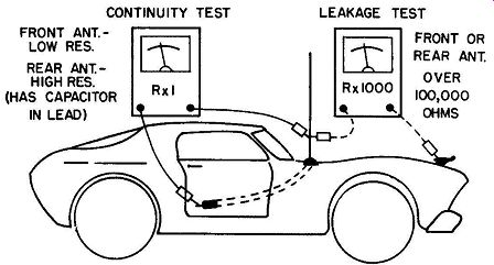
Fig. 8-3. Ohmmeter tests for an auto radio antenna.
Also, if the antenna is not matched to the radio, station fading, mixing, and excessive whistles will be heard.
An antenna trimmer capacitor is accessible on the out side of all auto radios for this purpose (Fig. 8-4). It should be peaked for maximum volume while tuned to a weak station or noise near 1400 khz. This adjustment is much more critical on transistor than tube radios.
Isolating Troubles in the Radio
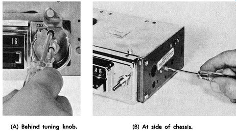
(A) Behind tuning knob. (B) At side of chassis.
Fig. 8-4. Location of antenna trimmers.
Assuming that the trouble is in the radio, we must quickly determine what section it is in, and then track it down to the exact stage and component. When the chassis is removed, first take time to look it over carefully. Become familiar with the location of the various stages. Fig. 8-5 shows a typical all transistor auto radio and the location of the transistors. A schematic of this same unit is given in Fig. 8-6. By looking over the circuit and coordinating it with the chassis layout, you will know where to look for the various sections and have a mental block diagram of the unit.
Important points to remember when checking an auto radio on the bench are:
RF AMP CONV. 1st IF
IF AMP AF AMP 2nd IF TRANSFORMER
TRANSFORMER
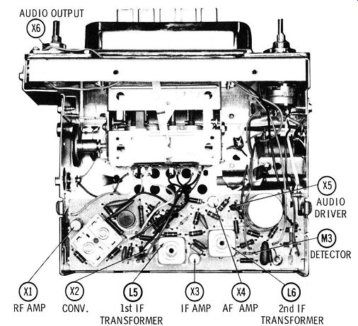
Fig. 8-5. Top view of a typical auto radio.
1. Make sure the polarity of the supply voltage is correct.
2. Make sure the speaker is connected properly.
3. Make sure the rated input voltage is used while measuring voltages; but vary the input above and below that voltage before releasing radio to owner ( car voltages do not remain constant).
4. Make sure radio is tapped and vibrated all over to test for intermittents ( cars are in constant motion, causing all components to be jarred). Sometimes heat supplied by a hair dryer while the voltage is increased and the chassis tapped (Fig. 8-7) will cause intermittents to show up.
----------------------
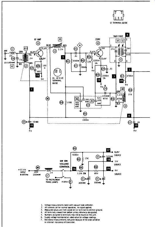
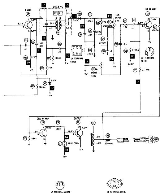
Fig. 8-6. Schematic of the auto radio pictured in Fig. 8-5.
---------------------
Checking the Audio System The audio system is checked first. If it is working properly, it will produce the normal thump when turned on, the output transistor will have normal collector voltage, and a good noise will be heard when injected at the volume control. If radio fails any of these tests, proceed as follows.
Troubleshooting the Output Stage As the radio is turned on, the surge of output current in most models causes the speaker cone to move and a slight thump is produced. This is not true in push-pull output circuits, where the idling current is small.
The lack of thump in radios which normally have it can be caused by (1) the speaker not being connected, (2) an open fuse resistor, (3) a defective power transistor, (4) a short in the insulator between output transistor and its heat sink, or (5) any defect which prevents the output transistor from con ducting current.
Fig. 8-8 shows how to make certain that the speaker, output transformer, and transistor insulator are all right. Set the ohmmeter on the R X 1 range and clip one lead to chassis. Tap or rub the other lead on the case (collector) of the output transistor. If a popping or scratching sound is heard, you can free your mind of everything between collector and speaker.
Things which can prevent the pop are: (1) open speaker, (2) shorted interlock switch (used on older models), (3) shorted transistor insulator, (4) shorted collector bypass capacitor (if present), and (5) shorted output transformer.
Let's assume that a radio produces no thump when turned on, but the above ohmmeter test causes a noise. The trouble must be somewhere before the collector circuit, such as an open fuse resistor (emitter circuit), or shorted transistor and open fuse resistor (Fig. 8-9). In both cases, the collector voltage of the DS-501 is zero, because no current can flow through output transformer L3. However, in Fig. 8-9A the emitter voltage is 12 volts and in Fig. 8-9B, it has zero voltage.
Adjusting the Transistor Bias
Assume now that the trouble turns out to be a shorted power transistor (emitter to collector short), and an open fuse resistor (Fig. 8-9B). These are the most common problems in power output stages.
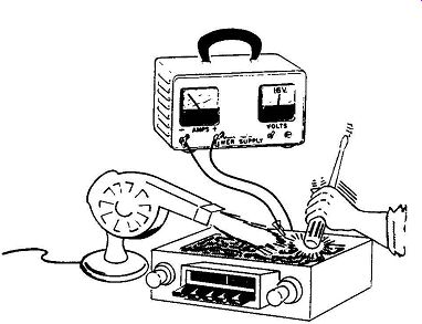
Fig. 8-7. Tapping the chassis, applying hHt from hair dryer, and increasing
input voltage to help locate intermittents.
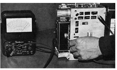
Fig. 8-8. Checking speaker and output transformer (and connections) by tapping
ohmmeter (R X 1 range) on case of output transistor.
After replacing the parts, the collector voltage of the output transistor should be checked. If it doesn't read what the schematic specifies, the transistor bias control, R4, must be adjusted until proper collector voltage is obtained. This sets the transistor at the proper operating point for minimum distortion.
It must be adjusted with the speaker connected, and the rated supply voltage applied to the radio (see schematic of individual radio) . A word of caution: If the bias control cannot bring the col lector voltage down to the value listed on the schematic, check the bias resistors. The shorted transistor often causes R3 to increase in value, so that the new transistor can't be set properly. If this happens, R3 must be changed to prevent a repeat failure. Also, always replace the fuse resistor with the exact manufacturer's replacement. Do not substitute, as damage to components and even fire can result. Fuse resistors are not only £usable resistors, but they also provide temperature compensation-the value varies with temperature to prevent transistor "run-away."
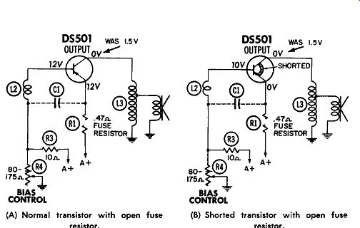
(A) Normal transistor with open fuse resistor. (B) Shorted transistor with
open fuse resistor. Fig. 8-9. The most frequent output stage troubles.
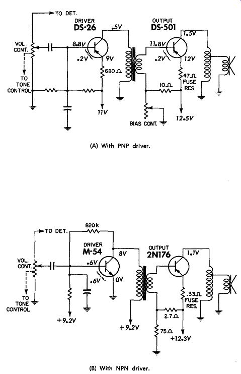
(A) With PNP driver. (B) With NPN driver. Fig. 8-10. Two popular audio systems.
Troubleshoot the Driver Stage
Now let's assume that a "thump" was produced when the radio was first turned on, but no signal is heard when injected at the volume control by a noise generator. This tells us that the trouble probably lies in the audio driver stage. Before checking the driver, however, make a quick check of the out put stage collector voltage, just to be sure that all is well there.
If all right, proceed as follows.
Fig. 8-10 shows two popular drivers-NPN and PNP. In the PNP circuit (Fig. 8-lOA), transistor conduction or idling cur rent can be checked two ways. The quickest is to measure collector voltage to ground. If .5 volt is found, conduction is probably normal. The other method is to measure voltage across the 680-ohm emitter resistor. If about 1.0 volt is found, conduction is normal. This can be used as a confirming test or a "double check" of conduction.
If conduction is normal, chances are all DC components (transistor, resistors, and transformer winding) are good, and the trouble is probably an open capacitor.
If conduction is low, measure the bias to determine if the trouble is in transistor or circuit. (Low conduction with good bias usually means transistor trouble; low conduction with zero bias usually means base or emitter circuit trouble.)
If the conduction is high, measure the bias to determine if trouble is in transistor or circuit. (High conduction with good bias usually means circuit trouble; high conduction with low or reversed bias usually means the transistor is leaky or shorted.) The NPN driver in Fig. 8-10B is checked in the same manner, with two minor differences: (1) Conduction can only be checked by measuring from collector to the 9.2 volt line, since there is no emitter resistor, and (2) the normal bias is .6 volt instead of .2 volt, because the transistor is a silicon unit.
It is important to notice that the same basic rules that we learned for other transistor radios are used for auto radios.
First, a general idea of the trouble area is obtained, then transistor conduction and biases are checked. This quickly gets you down to one part of a circuit, where individual components can easily be checked.
Direct-Coupled Audio Systems
In recent years, direct coupling from one audio stage to another has become popular. This eliminates the need for interstage transformers but makes troubleshooting a little more difficult, because the conduction of each stage in the system is dependent on the other stages.
Fig. 8-11 shows a typical schematic. Driver AF-1 is a PNP transistor, and AF-2 is an NPN unit. This is typical of Ford circuits. General Motors radios use NPN transistors in both driver stages.
The conduction of transistor AF-1 through R4 produces .6 volt across that resistor. Since R4 is connected between the base and emitter of AF-2, this provides the proper bias for AF-2. The conduction of AF-2 through R6 produces .2 volt, which is the bias for the 2Nl227 output transistor. Thus, each transistor is dependent on the previous one for its bias and conduction. While this has some disadvantages in troubleshooting, it also has a definite advantage. The DC condition of all audio stages can be checked by measuring one voltage--the output transistor collector voltage. Normal conduction there means that the two drivers are also conducting properly.
What if the conduction is not normal? Check the conduction and bias of each stage, beginning with AF-1, to see where the trouble is located. Shorted or open transistors can easily be located. Silicon drivers seldom fail, but when they do, they almost always go completely open or shorted between two elements.
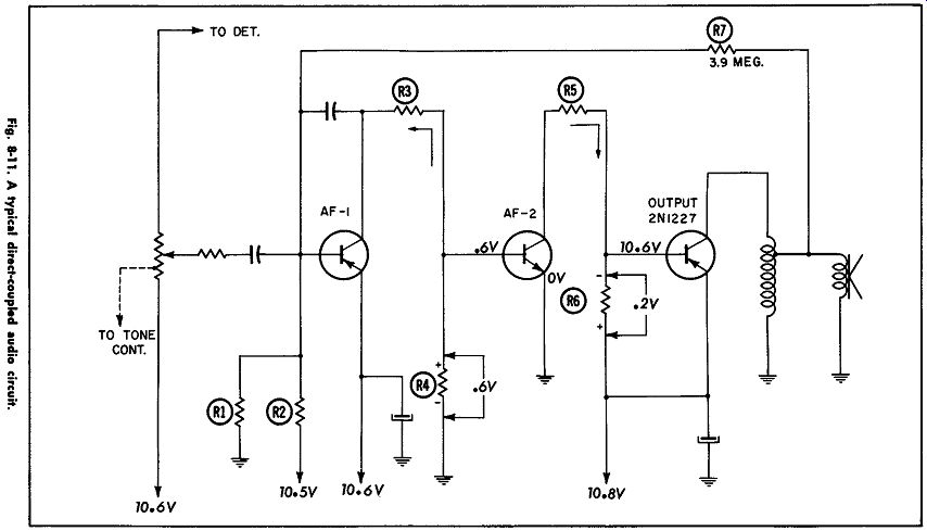
Fig. 8-11
If noise is produced by a direct-coupled circuit (high hiss or squeal), bridge each electrolytic capacitor in the audio system and power supply with a good capacitor of the same value. If this doesn't locate the defective part and AF-1 is a PNP transistor, replace AF-2 (NPN unit). Checking the "Front End" If the audio system is working properly, turn the volume control up and see if the radio has the normal "background" hiss. Since most of the noise is produced in the RF stage, this test will tell you how much of front end is working. If the IF or converter stages are malfunctioning, there will probably be no hiss level at all. If the RF stage is not operating properly, there may be a small hiss level present.
A typical auto radio front end is shown in Fig. 8-12. The most important check to determine the condition of each stage is the emitter voltage drop ( conduction) . Some manufacturers are even showing the voltage across each emitter resistor on their schematics. If conduction of one of the stages is not near normal, check the bias to see if the transistor is being "told" to conduct.
As in previous transistor amplifiers, normal DC conduction eliminates the transistor, resistors, coil windings, and connections to each of those parts. This checks practically all components in that stage except the capacitors and tuned circuits which, of course, do not affect the DC conduction of the stage.
The best way to illustrate how this knowledge will help you locate troubles is to take some examples and show how the troubles were found.
Locating Troubles Which Affect Conduction
Assume that the audio stages were found to be performing perfectly and that turning the volume control up produces no hiss level-the front end is completely dead. Conduction of the IF stage is checked by measuring the voltage drop across R3.
This voltage measures zero (instead of 1.2 volts). No signal is produced when a noise generator is touched to the IF base.
The bias measures .9 volt (instead of .2 volt). Thus, the bias is high, but the transistor isn't drawing current. By using an ohmmeter on the R X 100 range, we find that the emitter diode (between B and E) reads 2000 ohms in one direction, and higher when the ohmmeter polarity is reversed.
Conclusion--The IF transistor is open.
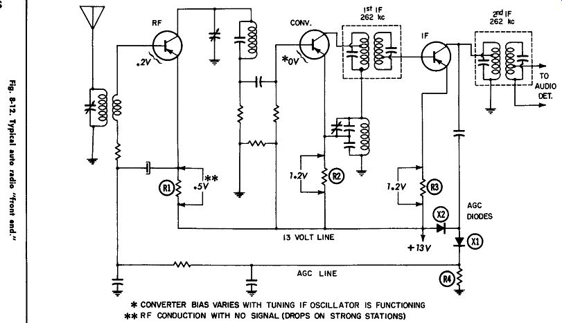
Fig. 8-12
Let's take another example. The radio is very weak. Conduction of the RF transistor (measured across R1) is 1.5 volts (instead of .5 volt). Bias is very low (near 0). Thus, the transistor is being told not to conduct, but it is conducting heavier than normal. A new transistor is tried, and the radio is normal.
Conclusion--The RF transistor was leaky. A word of caution, however. Note that the base circuit of the RF stage is connected to the AGC ( automatic gain control) system to control its gain. An open AGC diode can also cause high conduction of the RF transistor. In that case, however, conduction will be high, but bias will be normal or slightly high because AGC diodes X1 and X2 form one leg of the voltage divider for the RF base circuit (R4 completes the divider circuit). Locating Troubles Which Don't Affect Conduction
Let's assume that a radio is received which cuts out. The audio system checks good. All conductions are normal in the RF, converter, and IF stages. The circuit board and all components are tapped. When the 2nd IF coil is wiggled from side to side, the radio cuts out, but the IF conduction stays normal (1.2 volts). Since conduction stays normal, the trouble is probably an open capacitor or detuned coil.
Conclusion-The IF coil is suspected and changed-the radio is then O.K. The mica capacitor inside the IF can was cracked, causing the coil to detune.
Another radio cuts out intermittently, and sometimes stations "drift" toward the left end of the dial. This indicates oscillator (converter stage) trouble, but all conductions and voltages check normal. When tapping components, it is found that the oscillator trimmer adjustment screw is very sensitive, sometimes causing the radio to cut out.
Conclusion--The oscillator trimmer is defective. Replacing and aligning it cures the trouble. (This was the most common defect in 1963 GM car radios. The trimmer was redesigned with silver contacts internally, to prevent the capacity from shifting value.)
Short-Cut Test of "Front End"
There is a short cut test of the front end, similar to the direct coupled audio test. You will recall that because all audio stages are coupled together in some radios, the conduction check on the output stage checks the DC circuits in the entire audio system.
In one way, the front end stages of most auto radios are also "tied together" -by the AGC system. The AGC samples the output of the IF stage, rectifies the signals present there, and feeds a DC voltage back to the base of the RF transistor.
The DC voltage reduces the forward bias on the RF stage, causing it to conduct less and reducing its gain. The stronger the station, the stronger the AGC voltage. This cuts off the RF stage to prevent the radio from "blocking" or distorting on strong stations.
If all three stages in the front end are working properly, the output at the IF will be good. This will cause a reduced forward bias on the RF transistor and reduced conduction only when tuned to strong stations. So, by measuring conduction of the RF stage while tuning through strong stations, a check of the whole front end is made. If the conduction goes to almost zero, the entire system is functioning. Chances are the conduction as well as tuned circuits in all stages are functioning, with possible exception of the 2nd IF coil secondary which this method does not check.
TROUBLESHOOTING SUMMARY
The most important aid in troubleshooting is to use a systematic procedure. Follow a set procedure on every radio. The hunt and poke method is time-wasting and strictly taboo.
Conduction checks are recommended before signal injection because the latter will sometimes shock intermittent troubles back into operation. Where conduction checks do not reveal the trouble, use a noise generator to isolate the defective stage.
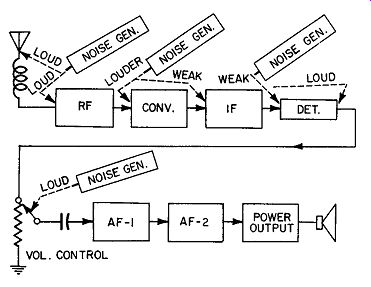
Fig. 8-13. Noise generator checks.
Fig. 8-13 shows what to expect when the noise generator is used at the various points in the circuit. Merely touch the noise generator to the various points on the printed circuit board (Fig. 8-14) and listen to the output. The results expected at each point are summarized in Table 8-1. The volume control should be turned all the way up when making tests.
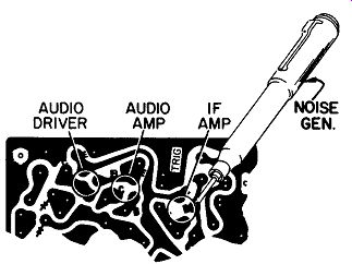
Fig. 8-14. Touching noise generator to printed board.
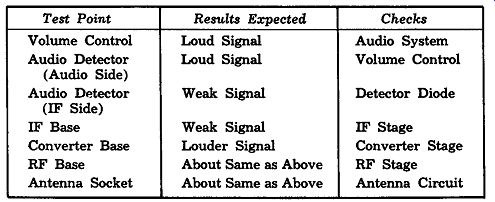
-------------------- TABLE 8-1.
Noise Generator Tests
Test Point Results Expected Checks
Volume Control Loud Signal Audio System
Audio Detector Loud Signal Volume Control (Audio Side)
Audio Detector Weak Signal Detector Diode (IF Side)
IF Base Weak Signal IF Stage
Converter Base Louder Signal Converter Stage
RF Base About Same as Above RF Stage
Antenna Socket About Same as Above Antenna Circuit
------------------------
Basic Procedure
The following procedure, taken in the order given will quickly lead you to the cause of any trouble in auto radios.
1. TURN RADIO ON, OBSERVING SPEAKER CONE MOVEMENT. If no speaker action, check speaker connections. Ohmmeter (on R X 1) should produce scratching noise at collector of output transistor.
2. TRY ALL CONTROLS. Volume, tone, manual, push buttons.
3. REMOVE TOP COVER AND LOOK RADIO OVER CAREFULLY.
4. MEASURE COLLECTOR VOLTAGE OF OUTPUT TRANSISTOR. This checks audio amplifier, driver, and power output stages (except capacitors) in direct-coupled systems.
5. MEASURE CONDUCTION OF RF TRANSISTOR: WHEN TUNING THROUGH STRONG STATION FRE QUENCIES, VOLTAGE SHOULD DIP TO A LOW VALUE. This checks RF, Converter, and IF Stages, and the AGC diodes. If no dip is obtained, measure current flow of each stage.
6. INJECT SIGNAL (Table 8-1).