The vertical-sweep section is straightforward, particularly in older model receivers which utilize separate oscillator and output stages.
The trend in newer receivers is toward simplified circuitry in which the two functions are combined, as shown in Fig. 8- 1. Interaction of oscillator and output functions results in some added complexities of trouble analysis. If the scope is properly applied, however, operating troubles can be localized with reasonable effort.
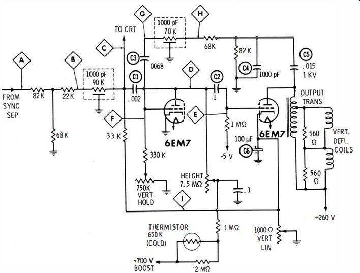
Fig. 8-1. Typical vertical-sweep configuration.

Fig. 8-2. Integrator Input
waveforms. (A) Input waveform at point A of Fig. 8-1. (B) Change in waveform
when picture is split.

Fig. 8-3. Normal waveforms at input and output of integrator. (A) Waveform
at point B. (B) Waveform at point C.
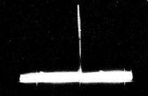
Fig. 8-4. Waveform at point C when the picture is split.
VERTICAL SYNCHRONIZATION
The vertical oscillator cannot lock in sync unless the sync separator supplies a suitable pulse to the integrator. Normal output from the separator is shown in Fig. 8-2A. The prominent pulse in the pattern consists of both the stripped vertical-sync pulse and a larger "kickback" pulse from the 6EM7. The two pulses can be separated by adjusting the vertical-hold control for a split picture. The vertical sync pulse then appears like the smaller pulses in Fig. 8-2B. If the picture is rolling because of a defect in the vertical section, the sync pulse will ride through the pattern and the scope will lock on the larger pulse.
If a normal vertical-sync pulse is not present, turn your attention to the sync separator. But if the input is normal, proceed to check at the input and output terminals of the integrator. The integrator has substantial input capacitance. Therefore, signal passage from point A to point B through the resistive network results in elimination of most of the horizontal sync pulses which were evident in Fig. 8-2.
Normal waveforms at the input and output of the integrator unit are shown in Fig. 8-3.
Integration largely eliminates the horizontal pulses, and the vertical pulses are somewhat attenuated also. Because the output of the integrator is coupled to the plate of the first 6EM7 section, the "kickback" pulse is comparatively increased in the waveform. Thus, if the waveform at point C is observed when the picture is split, the vertical sync pulses have a relatively low amplitude, as shown in Fig. 8-4. Because relative pulse amplitudes differ considerably from one circuit configuration to another, always check the receiver service data for the particular chassis. No visible "kickback" pulse is found at the output of the integrator in some receivers.
The chief consideration at this point is the presence of a normal vertical sync pulse and the virtual elimination of horizontal pulses.
Otherwise, vertical lock is unstable or absent. If integrator defects permit feed through of horizontal pulses, interlacing will be poor and the picture will lack full definition. Note that defects in the oscillatory circuit will reduce the amplitude of the "kickback" pulse, or it may be absent altogether. But this does not affect the amplitude of the vertical sync pulse. If the sync pulse is not present at point C, look for a shorted capacitor in the integrator assembly. Note also that point C is connected to the vertical blanking network. A shorted capacitor in this network can greatly reduce or even "kill" the sync pulse.
COUPLING-CAPACITOR CHECKS
Even though ample sync is being supplied, defective vertical operation can be caused by defective coupling capacitors. This is a more common cause of off-frequency operation or unstable lock than are defective resistors. C1 and C2 are immediately suspected if a normal waveform (Fig. 8-5) is not observed at point D in Fig. 8- 1. The coupling capacitors should be tested first for leakage on a capacitor checker, at rated working voltage. If the leakage resistance is very high (note that the capacitors must operate in a high-resistance circuit), check next to see whether either of the capacitors is open or has lost substantial capacitance. If a capacitor checker is not available, make a substitution test.
If C1 is low in value, the picture becomes nonlinear vertically. Also, the waveform at point D becomes distorted as seen in Fig. 8-6. The waveform amplitude increases because the integrator network loads the oscillator to a lesser extent. Similarly, if C2 is low in value, the normal waveform at point E becomes distorted, as shown in Fig. 8-7.
If the coupling capacitors are all right, do not leave this branch of the circuit until the height control is checked out. It can become worn, with resulting change in resistance value and stability of adjustment.
In particular, if the oscillator operates normally for a length of time, following which the oscillator "pulls" excessively and breaks vertical lock, an unstable height control should be suspected.
A defective height control can be simulated falsely in some cases by a defective thermistor (6S0K cold resistance shown in Fig. 8- 1). Thermistors tend to increase in value after an extended service period.
The function of the thermistor is to maintain constant vertical sweep with usual variations of supply voltage due to line-voltage fluctuation.
But if this branch of the circuitry checks out satisfactorily, turn your attention to the feedback branch of the oscillator.

Fig. 8-5. Normal waveform at point o of Fig. 8-1.

Fig. 8-6. Waveform at point 0 when C1 is low in value.

Fig. 8-7. Normal and abnormal waveforms at point E. (A) Normal waveform. (B)
C2 low in value.
FEEDBACK WAVEFORMS
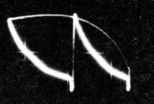
Fig. 8-8. Normal waveform at point F.
The normal waveform for this circuit at point F is shown in Fig. 8-8. If distorted or low in amplitude, check the waveform also at point G. The normal waveform is shown in Fig. 8-9A. A typical distorted waveform which results when C3 is low in value is shown in Fig. 8-9B. The vertical oscillator speeds up, and the picture cannot be locked.
The increased oscillator frequency causes additional cycles to appear in the pattern when the scope is deflected at a 30-Hz rate. Leakage in C3 has much the same effect as capacitance loss because the negative dc grid bias is bled to ground.

Fig. 8-9. Normal and abnormal waveforms at point G. (A) Normal waveform. (B)
C3 low in value.
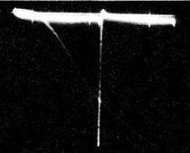
Fig. 8-10. Normal waveform at point H.
A defect in the vertical-hold control can simulate leakage in C3, but is a less common cause of trouble. An ohmmeter check should indicate rated resistance value, without any rough spots as the control is turned through its range. When the foregoing components are cleared from suspicion, make a waveform check at point H. The waveform appears normally as in Fig. 8- 10. Incorrect shape and/or amplitude indicates a faulty component in the coupling unit or in the components between point H and the output transformer. Each should be checked out in turn.
It is generally undesirable to check waveforms at the plate of the output-tube section or in its near vicinity. The amplitudes are comparatively high, and a low-C probe can be damaged. Note that CS is a 1-kV capacitor. It cannot be checked properly on an ordinary capacitor tester; a substitution test is advised. C4 is a conventional capacitor. If it is open, however, the pulse voltage across the 82K resistor will rise excessively because of the loss of capacitor-divider action.
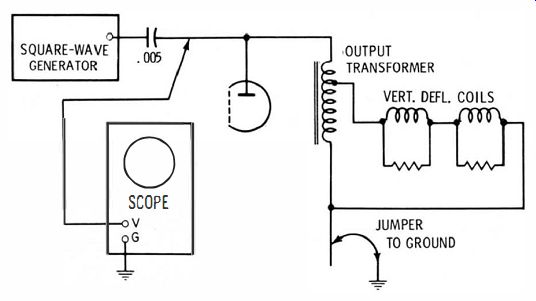
Fig. 8-11. Test setup for shorted turns.
VERTICAL-OUTPUT TRANSFORMER
Troubles in the vertical-output transformer may or may not be readily apparent . If there is a breakdown between windings or from winding to core, arcing will occur which is often audible. Such arcing causes the picture to fluctuate erratically in height. A direct short between turns or leakage between layers produces a steady trouble symptom of insufficient height. Note carefully the difference in symptoms between shorts in the transformer and in the yoke; the former reduces picture height, while the latter causes keystoning. Thus, yoke faults are more easily localized.
A good confirming test for shorted turns in the output transformer can be made with a square-wave generator. The receiver is turned off, and a square-wave generator is connected as shown in Fig. 8-11. No circuit disconnections are required. The inductance of the output circuit normally distorts a 10-kHz square wave as seen in Fig. 8-12.
The long curved portion of the waveform is an indicator of the circuit inductance with respect to the circuit resistance. Shorted turns absorb energy and not only reduce the inductance, but also introduce an effective ac resistance. Hence, shorted turns cause a marked change in the square-wave response, as illustrated in Fig. 8-12.
To summarize, the square-wave test is made after it has been determined that reduced picture height is not due to faulty capacitors or resistors, and after you are certain that the vertical sweep does not fluctuate and that audible arcing is not occurring. If audible arcing is occurring, however, the output transformer should be replaced without making any further tests in the circuit.

Fig. 8-12. Results of shorted-turns test. (A) Normal 10-kHz square-wave response.
(B) Shorted turns in output transformer.

Fig. 8-13. Normal and abnormal waveforms at point I. (A) Normal waveform.
(B) C6 low in value.
CATHODE CIRCUIT
The normal cathode-circuit waveform is checked at point I and appears as illustrated in Fig. 8-13. The usual troublemaker here is 100 uF electrolytic capacitor C6. As the capacitor ages, it tends to lose capacitance. Also, the picture becomes so nonlinear that the vertical
linearity control must be turned to the end of its range. A waveform check then quickly shows the deficiency, as in Fig. 8-13. It might be supposed that the fine structure of the waveform would become more prominent when C6 loses capacitance, but the opposite is true. The reason for this is that the 60-Hz component increases rapidly in amplitude compared with the horizontal cross talk which is picked up.
If C6 has merely lost capacitance, a bridging test with a good electrolytic unit will restore normal operation. However if the trouble is due primarily to leakage, a bridging test may be inconclusive. In that case, C6 should be checked at its working voltage on a capacitor tester, or a substitution test should be made.
VERTICAL-BLANKING NETWORK
Most present-day receivers have vertical-blanking networks to cut off the picture tube during vertical-retrace time. In theory, blanking should not be required, but it is desirable in practice because viewers sometimes operate the picture tube at higher brilliance than normal.
This makes the blanking pedestals in the video signal inadequate to their task. Also, not all receivers have dc coupled video amplifiers.
This situation intensifies the problems of retrace visibility. When an ac coupled video amplifier is used, the operating point of the picture tube shifts with changing background brightness in the televised scene. As a result, retrace lines will become visible in certain scenes, depending on the background brightness level.
Again, as a picture tube weakens, the viewer automatically turns up the brightness control to compensate for lower screen output. This shifts the picture-tube operating point abnormally, and brings up the visibility of vertical-retrace lines. These considerations weigh in favor of vertical-blanking networks, as shown in Fig. 8-14. A scope provides an easy method of closing in on circuit faults. Check first the output at point A. The blanking-pulse amplitude should be sufficient to cut off the picture tube, and this peak-to-peak voltage is usually specified in the receiver service data. If coupling capacitor C1 is open or low in value, the waveform amplitude will be subnormal, as illustrated in Fig. 8-15. In case C1 is open, the normal waveform will be found, of course, at the input end of C1, at point C.
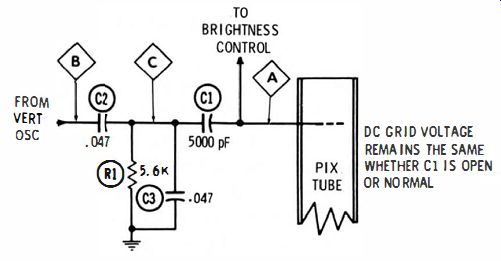
Fig. 8-14. Vertical-retrace blanking circuit.
The normal waveform at point B is shown in Fig. 8-16. If the vertical-sweep section is operating normally otherwise, absence or distortion of this waveform is the result only of a poor connection to the input blanking network. With a normal waveform at point B, check next at point C, to determine whether C2 is open. Note that leakage in C2 makes it impossible to lock the picture vertically.
R1 and C3 serve two functions. In combination with C2, this is a waveshaping network which changes the peaked sawtooth input into a pulse output for proper blanking action. Thus, if C3 is open, a distorted peaked-sawtooth wave is applied to the grid of the picture tube, and proper blanking action does not occur. The blanking action, however, is very uneven and part of the picture is dimmed or blanked out completely. The blanking network also has a voltage-divider action which prevents excessive peak voltage from being applied to the picture-tube grid. Although capacitor trouble is first to be suspected, be sure to check R1 if necessary.

Fig. 8-15. Waveforms at point A of Fig. 8-1 4. (A) Waveform when C1 is normal.
(C) Waveform when C1 is open. (B) Waveform when C1 is low in value.
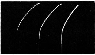
Fig. 8-16. Input waveform to the vertical-blanking network.
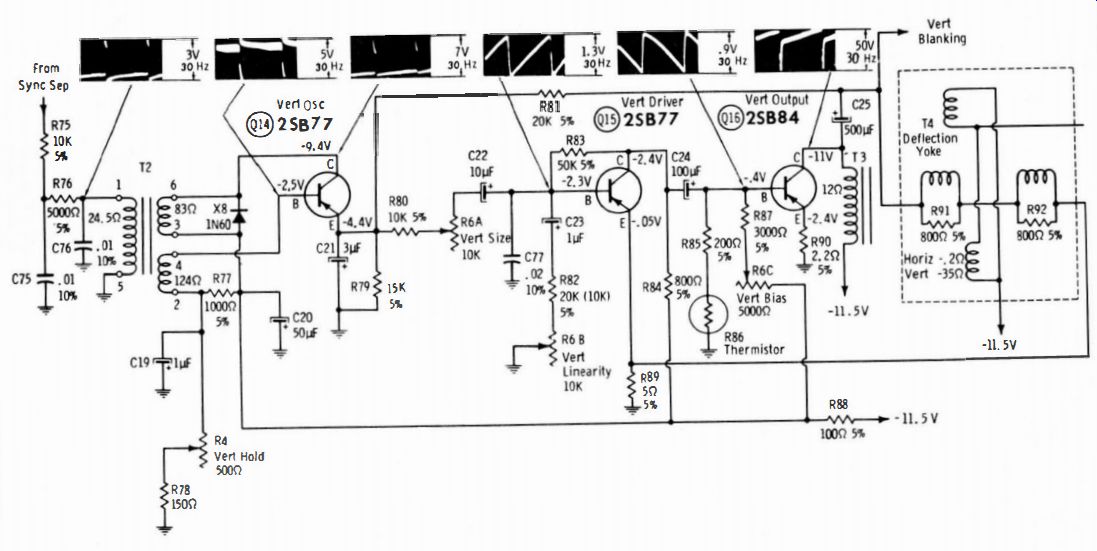
Fig. 8-17.
SOLID-STATE VERTICAL-SWEEP SYSTEM
A solid-state vertical-sweep system is shown in Fig. 8-17. It is very similar to its electron-tube counterpart. However, the solid-state circuits have low internal impedances (comparatively low voltages and high currents). Note that diode X8 is a protective device; it prevents excessive drive to the base of Q14, which could result in transistor damage. When picture trouble symptoms of vertical nonlinearity or subnormal picture height occur, scope tests are very helpful in localizing the defective circuit. As an illustration, if C22 becomes open, a sawtooth waveform will be found at the left-hand terminal but not at the right-hand terminal. Again, in case C24 loses a substantial portion of its capacitance, the driving waveform to Q16 will have less than O.9-V pop amplitude. Or, in case C2 1 becomes open, the driving waveform to Q 15 will have excessive amplitude and will be distorted.
There is considerable interaction between the driver and the output circuits in Fig. 8-17 because of the feedback loop via R81. As a result of this interaction, it is sometimes difficult to decide whether a fault that appears to be in the driver section might actually be in the output section. In other words, it is not necessarily true that distortion of the drive waveform to Q15 indicates trouble in the base circuit section of Q15, because a fault in the output network will be reflected back to the driver input circuit through the feedback loop. Therefore, scope tests must often be supplemented by dc voltage and resistance measurements to isolate a defective component. Note that tests in solid-state circuitry are often facilitated by the use of a high- low type of ohmmeter. In other words, an ohmmeter that applies less than 0.08 volt to the test points will not "turn on" semiconductor devices. Therefore, all normal semiconductors "look like" open circuits to this type of ohmmeter.
The principles established in the foregoing discussion apply to all of the numerous variations encountered in vertical-section circuitry. Keep in mind the basic circuit action, and always refer to the receiver service data when making waveform analyses.