AMAZON multi-meters discounts AMAZON oscilloscope discounts
The circuits that were examined in the previous chapter are termed "open-loop" voltage regulators. This chapter deals with so-called "closed-loop" voltage regulators. The difference between the two is that the closed-loop regulator makes use of a feedback system for voltage regulation. The change in output voltage of the power supply, due to either input-voltage variations or load-current change, is used to control a variable-resistance element in such a way as to bring the load voltage back to normal. This element may be either in series with or shunted across the load. The closed-loop system is capable of regulating output voltage much more closely with larger load-current variations than is an open-loop system.
FIG. 1 illustrates the basic concept of closed-loop voltage regulation. This configuration is known as a series-type closed-loop regulator. The component that provides the regulating action in this circuit is known as a losser element. It may be a transistor or a vacuum tube.
The losser element is placed in series with the output of the unregulated power supply and the load. The voltage applied to the load stays constant because the voltage drop across the losser is maintained at the difference between the power-supply output and the desired load voltage.
Voltage divider R1 and R2 is connected across the output of the power supply in parallel with the load. The voltage appearing at the junction of R 1 and R2 is applied as a signal to the losser element.
When there is an increase in load current the voltage across the load drops, causing a corresponding drop in voltage at the junction of R1 and R2. This decrease in voltage at the input of the losser element lowers its internal resistance. Less voltage is dropped across the losser so a greater voltage is applied to the load, bringing the load voltage back up to normal.
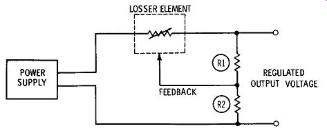
FIG. 1. Closed-loop series voltage regulator.
On the other hand, if the load current should decrease, the voltage across the load, and hence at the junction of R1 and R2, will increase.
This causes the voltage dropped across the losser element to increase because the internal resistance of the losser increases. A greater voltage loss across the losser element reduces the voltage across the load to its normal value. Now take a closer look at the various elements that make up the closed-loop series regulator.
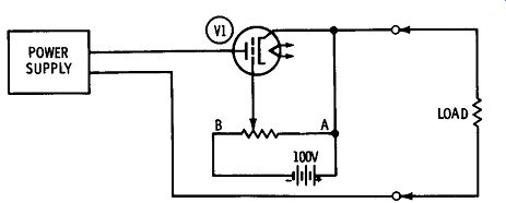
FIG. 2. Operation of series voltage-regulator element.
THE LOSSER ELEMENT
The operation of a vacuum-tube losser element (pass tube, as it is sometimes called) can be easily understood by referring to the circuit in FIG. 2. Tube V1 is connected in series with the load so all the load current from the power supply must pass through it. Because the control grid of V1 is connected to the arm of a potentiometer, the grid voltage can be varied from 0 to 100 volts negative with respect to its cathode.
A vacuum tube possesses an internal resistance between its cathode and plate (plate resistance), the amount depending on the construction of the tube. It ranges from a few thousand ohms for low-µ triodes to well over a megohm for pentodes. This resistance in a given tube varies with grid bias. It is a minimum when the control grid is at the same potential as its cathode, and it increases as the control grid is made more negative with respect to the cathode.
Referring to FIG. 2, when the control grid of the tube is at the same potential as its cathode (potentiometer set at A), the internal resistance of the tube is at a minimum. As a result, there will be minimum voltage drop across V1, and maximum voltage will be applied to the load.
As the slider is moved toward point B, the negative voltage applied to the grid (grid bias) increases, thereby increasing the effective internal resistance of V1. This increases the voltage drop across V1 so less voltage is applied to the load.
A SERIES VOLTAGE-REGULATOR OUTPUT
In order to use the capabilities of the pass tube, its internal resistance must be controlled in such a manner as to automatically correct for variations in load voltage. This is done as shown in FIG. 3, the circuit of a basic closed-loop series voltage regulator. V1, the pass tube, is connected between the output of the unregulated power supply and the load. A voltage divider consisting of R1, R2, and R3 is connected across the load terminals. A slider on R2 provides a feedback voltage that is used to control the pass tube.
When the voltage across the load drops because of an increase in load current, there is a corresponding voltage decrease between the tap on the voltage divider and ground. This voltage is applied to the control grid of V2, which operates as a direct current (d-c) amplifier.
Its purpose is to amplify the feedback voltage to a level sufficient to control the series pass tube ( V1).
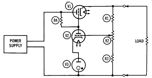
FIG. 3. Basic closed-loop voltage regulator.
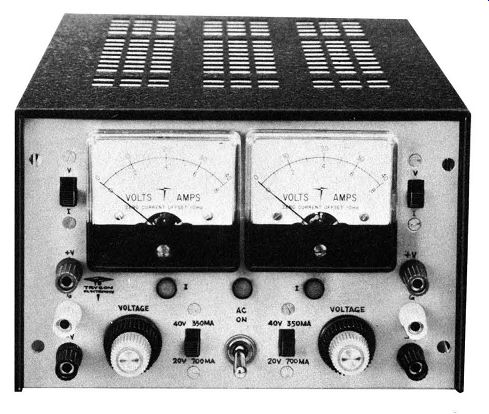
------ Courtesy Trygon Electronics, Inc. A dual, voltage-regulated power
supply. Output voltage is continuously variable and is regulated within
0.01 percent.
Since the V2 cathode is held at a constant voltage by gas-filled voltage regulator V3, a decrease in the grid voltage causes V2 to conduct less plate current. As a result, there will be a smaller voltage drop across plate-load resistor R4, and the plate will become more positive (less negative). Since the V1 control grid is directly connected to the V2 plate, the grid bias on V1 decreases, increasing the current through V1. There will be a lower voltage drop across V1, and more voltage will be applied to the load, bringing it back up to its original value.
When the voltage across the load increases, the voltage at the voltage-divider tap increases proportionally, causing the V2 control grid to become more positive with respect to its cathode. V2 conducts more plate current, and the plate voltage becomes less positive, as does the V1 control grid. With the increase in grid bias the internal resistance of V1 increases. This results in a greater voltage drop across V1, and the voltage across the load is reduced to its original value.
When the circuit in FIG. 3 is operating normally, there is a certain voltage on the slider of R2 that is applied to the grid of V2, amplified, and fed to V1 where it regulates the effective resistance of the pass tube. Any change from the normal voltage-caused by a change in load voltage-is called an error signal. In other words, the actual voltage on the slider of R2 minus the voltage present during normal operation equals the error signal. This can be positive or negative.
Tube V2 is sometimes referred to as an error amplifier.
While the simple circuit of FIG. 3 serves to illustrate the basic closed-loop series-regulator action, there are a number of changes that can be made to improve its performance. FIG. 4 shows a practical circuit. A triode-connected beam-power tube, V1, is used as the series pass tube. D-c amplifier V2 is a pentode rather than a triode in order to obtain greater amplification of the error signal.
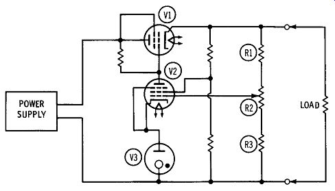
FIG. 4. Improved closed-loop voltage regulator.
The tap on the voltage divider connected across the load is made variable by means of potentiometer R2. This permits a range of output voltages to be selected.
FIG. 5 illustrates another arrangement. While the circuit operation is unchanged, two stages of d-c amplification, provided by V2 and V3, are used instead of the single pentode in the circuit of FIG. 4.
The voltage-regulating ability of the closed-loop circuit is improved as the gain of the d-c error-signal amplifier is increased. The increased gain means that a progressively smaller change in load current will be sufficient to control the series pass tube for voltage correction. however, as the gain of the d-c error amplifier is increased beyond a certain point, problems arise. The most important is variation in tube amplification. The series pass tube "sees" all changes in the d-c amplifier plate voltage as a change in load voltage, and compensates for it. As a result, the voltage across the load is varied by the d-c amplifier drift. This problem can be minimized by proper design of the multistage d-c amplifiers.
Another problem encountered in high-gain d-c error amplifiers is oscillation. These circuits are capable of amplifying a-c as well as d-c signals. As a result, unless the d-c amplifier is properly designed, phase shift at some high frequency can be great enough to cause oscillation.
The current-handling capability of the series regulator can be increased by paralleling series pass tubes, as shown in FIG. 6. When this is done, it is advisable to place isolating resistors in series with the plate and screen-grid leads.
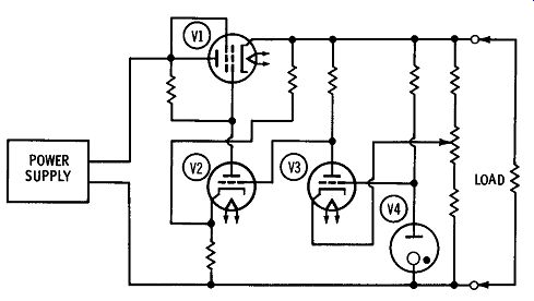
FIG. 5. Closed-loop voltage regulator using two-stage error-signal
amplifier.
Ripple Reduction
A bonus obtained from the closed-loop series voltage regulator is less output-voltage ripple. Refer to FIG. 6. Notice that resistor R4 has been placed between the tap on the voltage divider and the control grid of the d-c error-signal amplifier. Capacitor C1 is connected from the regulated voltage output to the control grid of V3. This capacitor has a low reactance at the ripple frequency (120 Hz for a full-wave rectifier), and so passes the ripple signal to the grid of V3. R3 has sufficient resistance to prevent the ripple signal from being bypassed to ground via the voltage divider R1-R2-R3. The error-signal amplifier (V3) "sees" the ripple voltage as a rapid change in voltage across the load and, as a result, tends to correct for this as well as for other changes in load voltage. For this reason less conventional filtering is required when a closed-loop regulator is added to a power supply.
Input-Voltage Variations
So far, the action of the closed-loop series voltage regulator has been described in correcting variations in load voltage caused by changing load current. It also compensates for changes in input voltage caused by line-voltage variations.
To see why this is so, refer to the basic closed-loop series voltage regulator in FIG. 6. When the line voltage increases, the power sup ply delivers a higher output voltage to the voltage regulator and load.
This increase in output voltage is then handled by the regulator in exactly the same manner as an increase in output voltage caused by a decrease in load current. A decrease in line voltage will cause the regulator to operate in exactly the same manner as if the load current had increased.
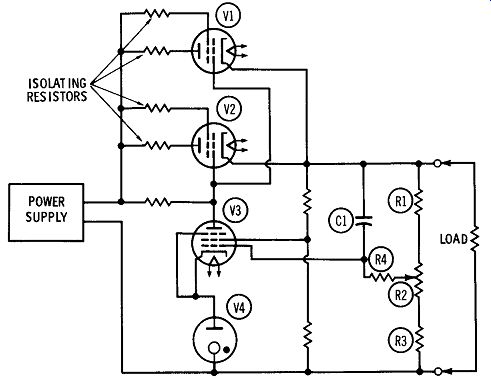
FIG. 6. Regulated power supply with multiple series control elements.
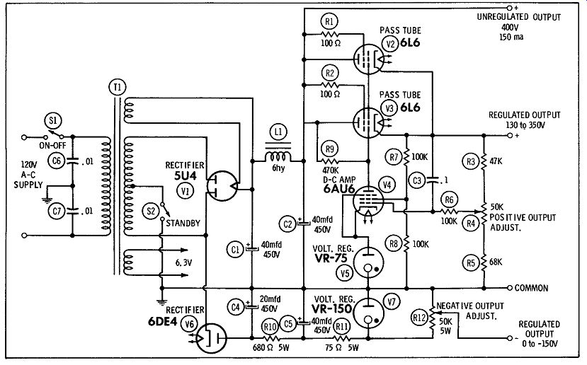
FIG. 7.
--------------
Parts List for FIG. 7
Item No. Description
C1 Capacitor, 40 mfd, 450 volts, electrolytic
C2 Capacitor, 40 mfd, 450 volts, electrolytic
C3 Capacitor, 0.1 mfd, mylar
C4 Capacitor, 20 mfd, 450 volts, electrolytic
C5 Capacitor, 40 mfd, 450 volts, electrolytic
C6 Capacitor, .01 mfd, mylar
C7 Capacitor, .01 mfd, mylar
L1 Choke, 6 hy, 200 ma (Knight 54D4704, or equivalent)
R1 Resistor, 100 ohms, 1 watt
R2 Resistor, 100 ohms, 1 watt
R3 Resistor, 47K ohms, 2 watts
R4 Resistor, variable, 50K ohms R5
Resistor, 68K ohms, 2 watts
R6 Resistor, 1 00K ohms, ½ watt
R7 Resistor, 100K ohms, ½ watt
R8 Resistor, 1 00K ohms, ½ watt
R9 Resistor, 470K ohms, ½ Watt
R10 Resistor, 680 ohms, 5 watts
R1l Resistor, 75 ohms, 5 watts
R12 Resistor, variable, 50K ohms, 5 watts
S1 Switch, spst
S2 Switch, spst
T1 Transformer, power.
Secondaries: 400 volts center-tapped, 200 ma; 6.3 volts, 5 amps; 5 volts, 2 amps (Knight 54D2033, or equivalent)
V1 Tube, 5U4
V2 Tube, 6L6
V3 Tube, 6L6
V4 Tube, 6AU6
V5 Tube, VR-75
V6 Tube, 6DE4
V7 Tube, VR-150
--------------
PRACTICAL CIRCUITS
Here are two practical voltage-regulator circuits that can be useful around your test bench, ham shack, or lab. The circuits are simple and straightforward, with no critical kinks to "debug."
Regulated Power Supply
FIG. 7 is a very versatile circuit, capable of supplying an unregulated
output voltage of 400 volts at 150 ma. The regulated voltage is continuously
variable from 130 to 350 volts at load currents up to 75 ma. In addition,
a 6.3-volt filament supply is furnished at a current rating of 3 amperes.
Finally, a regulated negative output voltage of zero to 150 volts is
provided. This power supply is ideal for the experimenter, ham, or service
technician working with vacuum tubes, because it provides such a wide
range of output voltages.
FIG. 7 is the schematic of the supply. The line voltage, controlled by on-off switch S1, is applied to the primary of power transformer T1. The center-tapped 400-volt secondary of T1, in conjunction with V1, forms a full-wave rectifier, the output of which is applied to the capacitor-input filter, C1-L1-C2. A standby switch, S2, is placed in the center-tap lead of the high-voltage winding. When this is turned to the OFF position, the heater voltage can be applied to the unit being operated from the supply without the B+. Thus, it is not necessary to turn off the entire, supply when you want to remove the d-c output voltage from the unit it is powering.
The positive voltage appearing at the junction of L1 and C2 is applied to the plates of the two series pass tubes, V2 and V3. The voltage is also applied to the screen grids through isolating resistors R1 and R2. The cathodes of V2 and V3 are both connected to the regulated positive output terminal of the power supply.
The voltage-divider network, R3, R4, and R5, is connected from the cathode of V2 and V3 to common (ground). R4 is the output adjust potentiometer; it connects to the control grid of d-c error amplifier V4 via isolating resistor R6. The cathode of V4 is held at a constant potential by gas-filled voltage-regulator tube VS. The V4 screen grid receives its operating voltage from voltage divider R 7 and RS. The plate of V4 is direct-connected to the control grids of series pass tubes V2 and V3. R9 is the V4 plate-load resistor. C3 reduces output ripple by feeding a small portion of the ripple voltage appearing in the regulated output to the V4 control grid.
The negative voltage output is obtained from half-wave rectifier V6. The cathode of V6 is connected to one side of the high-voltage secondary winding. The negative voltage appearing at the plate of V6 is filtered by an r-c network consisting of R10, C4, and CS. A simple r-c filter is used here, rather than an l-c filter, because of the low current that is anticipated. This is designed as a grid-biasing voltage, and there is normally no current in the grid circuit.
The output of the filter is kept steady by voltage regulator V7; R1 1 is the current-limiting resistor. A potentiometer, R12, is connected across V7; the slider of this potentiometer is connected to the negative output terminal.
----------------------
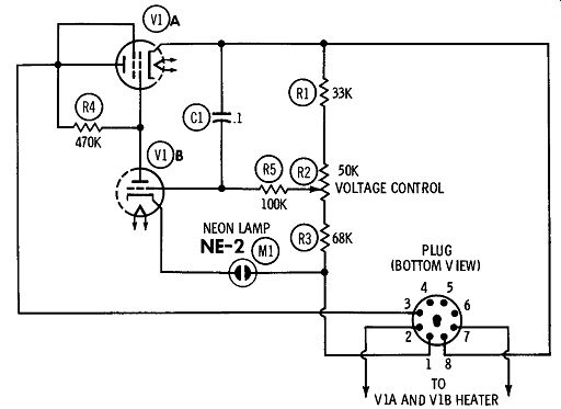
FIG. 8. Plug-in voltage regulator.
Parts List for FIG. 8
Item No.
C1 Ml R1 R2 R3 R4 RS V1
Description
Capacitor, 0.1 mfd, mylar
Lamp, neon, NE-2
Resistor, 33K ohms, 1 watt
Resistor, variable, 50K ohms
Resistor, 68K ohms, 1 watt
Resistor, 470K, ½ watt
Resistor, 100K ohms, ½ watt
Tube, ECL-80 or 6AB8
------------------------
A "Plug-In" Voltage Regulator
Here is a handy little voltage regulator ( FIG. 8) which offers the plug-in simplicity of a gas-filled voltage-regulator tube, yet it will provide considerably better regulation. Unlike a v-r tube, this has an adjustable output voltage and a higher current capacity (up to 50 ma.) In short, this small compact variable regulator may be just what you need.
As shown in FIG. 8, the circuit is that of a simple closed-loop series voltage regulator. It is a bit unusual in that the series pass tube and the d-c amplifier tube are contained in a single envelope. Also, a neon tube is used in place of the more conventional gas-filled voltage-regulator tube.
In operation, the unregulated voltage is applied through pin 3 of the plug to the plate of series pass tube V1A. The error signal appearing at the slider of voltage control potentiometer R2 is applied to the control grid of d-c error amplifier V1B. The plate of V1B is connected to the control grid of V1A; R4 is the plate-load resistor. The cathode of V1B is held at a constant voltage by an NE-2 neon lamp. It has electrical characteristics similar to those of a gas-filled voltage-regulator tube, although it is not cap able of handling as high a current.
The regulated output is available at pin 8 of the plug. Pin 1 is common to both input and output circuits.
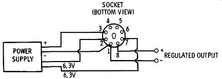
FIG. 9. Plug wiring for plug-in supply.
FIG. 9 shows how the completed plug-in voltage regulator is connected into a power supply which was formerly equipped with a voltage-regulator tube. The original wiring is removed from the v-r tube socket, and the socket is rewired as shown in FIG. 9. When the wiring is completed, remove the v-r tube and plug in the voltage-regulator "package." With power applied to the supply, set the "voltage adjust" potentiometer for the desired output voltage.