AMAZON multi-meters discounts AMAZON oscilloscope discounts
Solid-state devices are replacing some of the older, more familiar phototubes for many applications, including use as controls and sensors for computers. Punched paper tape and punched cards, for example, are often read by a matrix of photovoltaic cells. Here the reliability and smallness of solid-state sensors is important. As the light shines through the holes, different photo cells are excited and translate the punched holes into electrical signals. Other industrial devices use photoelectrics to shut off machines when the operator is in danger, and solar cells operate electronic equipment in remote areas and on satellites.
A typical industrial photoelectric use is in paper loop control.
Here the drive motors must keep a fixed loop between the paper rolls so the printing equipment will not jam. If the loop falls low enough to break the beam of light, the drive motor will slow down. If the loop is so short that it interrupts the upper beam, the motor will speed up. In the same way, computer tape transports use two photoelectric devices.
Light beams and photoelectric relays are also used in alarm systems. The photoelectric alarm consists of a projector and a receiver. A low-visibility beam, modulated at a specified frequency, is projected across the protected area. An infrared filter makes the beam invisible, even in the presence of smoke. Any interruption of this "black light" immediately triggers an alarm circuit. Attempting to bypass the system with another light beam; tampering with the projector, receiver, or housing; or opening a line will also trip the alarm circuit.
Photoconductive and photovoltaic devices as well as photo transistors are all used in these circuits. Photoconductive devices are thin layers of semiconductor material such as selenium, silicon, cadmium sulfide, lead sulfide, or lead selenide sealed in glass. When light falls on the cell, the resistance of the material decreases and the current flow through the load increases. This current How can be amplified for control, or it is possible to use a sensitive relay which closes when the current flow increases and thus controls a large amount of power through the relay contacts.
Photoelectric cells are also made from semiconductor materials, but they produce a voltage when light is applied. Because of this, they require no external power; actually, they convert light energy into electrical energy. An example of the use of photo voltaic cells is the installation of a large number of these cells to provide electricity for rural telephones. Several semiconductor compounds may be used for these cells, including silicon and selenium.
A silicon photocell generates energy by use of a PN junction to produce electrical energy from light. Pure silicon is a poor electrical conductor. However, by adding small amounts of impurity material to the silicon crystal, electron conduction will occur.
Classed as a phototransistor is the Photran, a bistable switch with many properties similar to those of a gas thyratron. It is essentially a PNPN switch triggered by light energy instead of, or in addition to, electrical energy. Before light strikes the Photran, it is in a high-impedance "off" state. When a light impulse is applied, it is switched to a low-impedance "on" state. The device will then remain on indefinitely until it is electrically turned off. The light energy used to trigger the device on need only be momentary, since it is not required to sustain the device in the "on" state. In this manner the Photran is like a light activated silicon-controlled rectifier.
PHOTOVOLTAIC THERMOMETER
Shown in this diagram is a self-powered Thermistor thermometer ( a Thermistor is a temperature-sensitive resistor). A selenium or silicon photovoltaic cell is used as a voltage source. As the temperature changes, the corresponding change in Thermistor resistance creates a bridge unbalance. When the calibrated rheostat ( in one of the arms of the bridge) is adjusted for a null meter reading, its position will indicate the temperature.
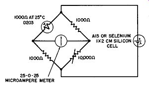
---------- Photovoltaic thermometer.
PHOTOCONDUCTIVE RELAY
The 7163 cadmium-sulfide cell is typical of the photoconductive type for use in control circuits. Part A of the diagram shows a high-sensitivity circuit using a half-wave, 75-mil selenium rectifier and an RC filter. Also used is a 250,000-ohm sensitivity control for the cell. When light falls on the cell, its resistance de creases. This allows more current to flow, and the relay closes.
This highly sensitive relay operates at 0.5 mil of current.
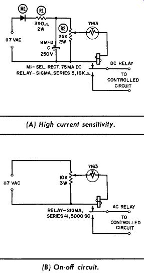
----- Photoconductive relay. (A) High current sensitivity. (B) On-off circuit.
For simple brute-force operation, the circuit in Part B uses pure line voltage and an AC relay. It has a lower sensitivity rating than the circuit in Part A, and is typical of the kind used in simple on-off applications.
PHOTODIODE CIRCUITS
Three separate circuits using a photodiode are shown in this diagram. Photodiode PHG-1 consists of one germanium junction diode polarized by a suitable voltage. The reverse current of this junction is very low in total darkness ( about 10 microamperes), but increases in proportion to the amount of light received by the cell.
In Part A of the diagram, a circuit for thyratron triggering is shown. Without light on the diode, the tube is nonconducting.
When light hits the photodiode, a positive drop across the 20K resistor overcomes the bias and the tube fires.
Part B shows a balanced circuit used for measuring the position of a light spot. The circuit will only be balanced if the light on both diodes is the same; any other condition therefore unbalances the output.
Part C illustrates a directly driven relay for control use. When light strikes the diode, the resultant current flow through the relay will energize it.
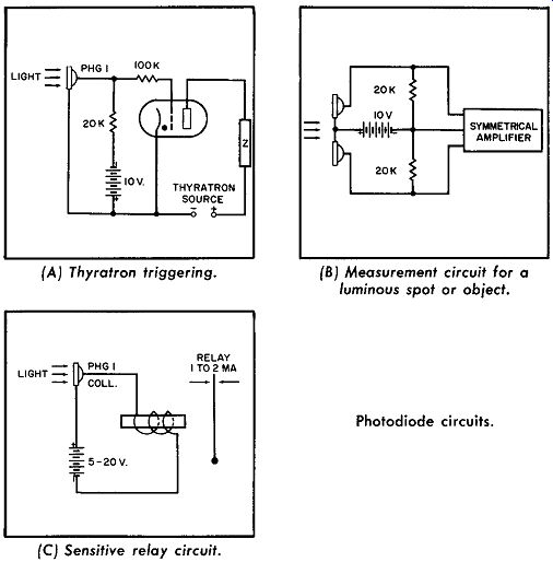
----------- Photodiode circuits. (A) Thyratron triggering. (B)Measurement circuit
for a luminous spot or object. (C) Sensitive relay circuit.
PHOTOCONDUCTIVE RELAY CIRCUITS
Several basic circuits using the PN photoconductive cell are shown in this diagram. The circuit in Part A uses a Type Bl5 photocell connected in series with a 6-volt battery and a Sigma Type 5F 16000S relay. With this combination, the relay will be actuated whenever a light intensity of more than 20 foot-candles hits the cells.
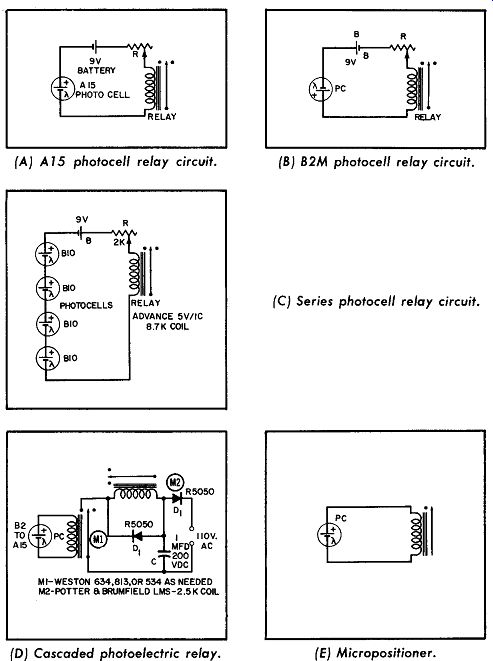
--------96 Photoconductive relay circuits. (A) A 15 photocell relay circuit.
(B) B2M photocell relay circuit. (C) Series photocell relay circuit. (D) Cascaded
photoelectric relay. (E) Micro-positioner.
Part B shows a similar photoconductive circuit with a different choice of photocell ( a B2M) and relay, for applications where the light intensity is 1,000 or more foot-candles. The relay is an Advance SV /IC with a 5,500-ohm coil.
Part C shows a circuit which has four BIO photocells in series and will function at 50 foot-candles.
This circuit can be used for counting or detecting passing objects, announcing the entrance of guests or customers, providing a protective light curtain around hazardous areas near machinery, etc.
A circuit with cascaded relays, driven by a photocell and incorporating a simple spark suppressor, is shown in Part D. In small-signal applications, relays are frequently cascaded to obtain greater controlling capacity. When this is done, the second relay is an inductive load on the first relay, and a spark-suppressing element is necessary on the second relay. M1 is a highly sensitive Weston meter-movement type of relay with limited contact capacity. It controls M2, a relay with five-ampere contacts. De pending on the size of photocell and the relay used, this circuit will respond to illumination of as low as 10 foot-candles. It is suited for such varied applications as automatic garage-door openers, burglar alarms, and counters ( of small objects passing by, for example). In operation, D1 rectifies the AC line current needed to operate the DC relay, M2. Capacitor C then smooths the rectified pulsating current. When the M1 contacts close, this current passes through power relay M2, closing its contacts. Diode D2 is a simple but effective spark-suppressing element which absorbs the inductive current when the relay Ml contacts break circuit relay M2. D2 thus eliminates arcing at the sensitive relay M1 contacts, which would shortly impair its function. The use of DC for the second relay makes possible this simple method of spark suppression.
Part E shows a photocell driving a Micro-positioner relay with out amplification. This is an A15 photocell and a Type AYLZ4529S relay; with 100 foot-candles, the relay will close.
PHOTODIODE RELAY CIRCUITS
In this figure three photodiode circuits are shown. Part A shows a block diagram of a light-detector circuit. The transmitted light is picked up by PHG-1. The resultant IR drop across the resistor then pulses the amplifier, which is used as a receiver in the system.
In Part B the relay is energized with no incident light applied to the photodiode, and de-energized with the application of light.
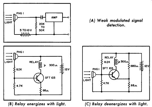
---------98 {A} Weak modulated signal detection. (B) Relay energizes with
light. (C) Relay deenergizes with light. Photodiode relay circuits.
There are two voltage dividers across the 12-volt supply. One leg is the photodiode and the 8.2K and 4.7K resistors. The other leg is the relay impedance and the emitter-to-collector circuit.
With the circuit rearrangement shown in Part C, the relay remains off until light hits the diode.
PHOTODIODE AMPLIFIERS
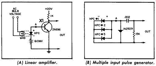
--------------- (A) Linear amplifier. (B) Multiple input pulse generator.
Photodiode amplifiers.
A linear amplifier, shown in Part A of the diagram, converts variations in light intensity to variations in output voltage. To illustrate this principle, a sinusoidal voltage has been applied to a W49 lamp. Light variations appearing at Part A as input-signal voltage are doubled in frequency because the bulb filament heats up during both the positive and the negative alternations of input voltage.
Part B illustrates one way that output pulses may be generated from multiple-input HPC readout cells in computer circuits, when the cells are subjected to light impulses passing through coded apertures.
RELAY DRIVEN DIRECTLY BY A PHOTODIODE
Relays may be operated directly from photovoltaic readout cells. This diagram shows a typical circuit of a photodiode-driven relay. Whenever a beam of light strikes the diode, the transistor conducts, picking up the relay.

------------ Relay driven directly by a photodiode.
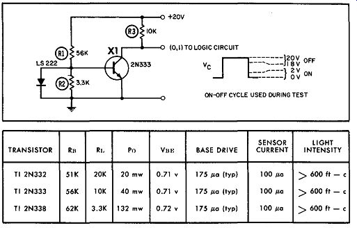
----------- (A) Silicon transistor on-off circuit.
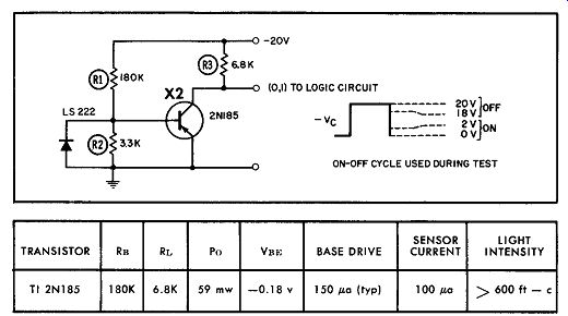
----------- (B)Germanium transistor on-off circuit. Photodiode light sensor.
PHOTODIODE LIGHT SENSOR
Part A of the diagram shows the LS-222, a diffused-junction silicon light diode used with a silicon transistor such as the 2N332, 2N333, or 2N338. With +20 volts on the collector, the transistor is off with incident light and the output is in the 18 to 20-volt range. When light is removed from the diode, the transistor output drops to the 0- to 2-volt range, as shown by the Ve waveform.
Part B shows the same circuit as A, but using a germanium transistor instead of silicon.