58. General
Any type of special transformer can be classified on the basis of operation frequency: power (60 Hz or similar power frequencies), audio frequency, or high frequency. Discussion of special transformers in this chapter has been reserved for this time because in each case, there is something unique about the circuit, the core, or the application. Our major concern deals with the manner in which the transformer differs from standard varieties in the same group, and the special applications encountered in the field.
59. The Autotransformer
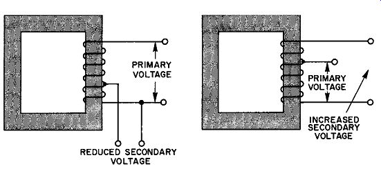
Fig. 37. Step-up and step-down autotransformer schematics.
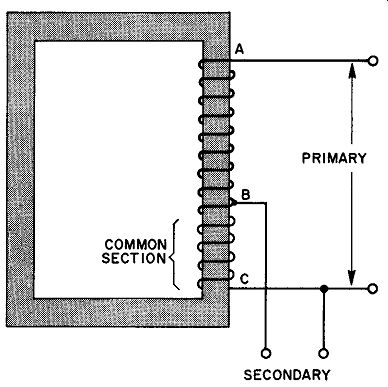
Fig. 38. The common winding may be of very thin wire under the right conditions.
Transformer principle can be applied to a single winding system, as well as to two windings. If power is applied to the terminals of a coil, lower voltages may be obtained by transformer action from taps on the coil. If the primary voltage is made to appear between one end of the transformer and a tap on the coil, higher voltages may be obtained across the end terminals. (See Fig. 37.) Autotransformers used in power applications are generally of the step-down variety. Referring to Fig. 38, it is evident that one section of the single winding is common to both the primary and secondary sections. Lenz's Law considerations indicate that the current flowing in this common winding must be 180° out of phase. Thus, the total current in the common section is the difference between the two. If the primary current approximates the secondary load current, the net current in the common winding may be very nearly zero. When the transformer is designed along these lines, the common section may be wound of very thin wire. This situation would occur only when the primary and secondary voltages are nearly the same value, and is found in those applications where the autotransformer is used to boost, or reduce, the line voltage by relatively small amounts.
The isolation obtained between the primary and secondary of a two-winding transformer is absent in the autotransformer.
This is a definite disadvantage when such isolation is desirable, as in transformers which isolate the power lines from radio chassis or other exposed metallic parts. Autotransformers cannot be used where d-c blocking is needed as, for example, in audio-coupling networks from the positive plate of one tube to the negative grid of the next tube.
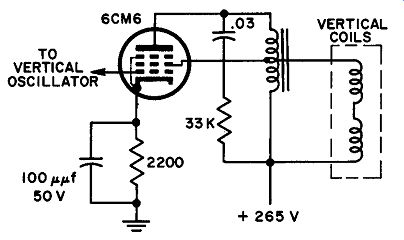
Fig. 39. Autotransformer vertical output system.
Many modern television receivers utilize autotransformers in their sweep circuits. One common vertical output circuit in which an autotransformer supplies the deflection coils with the vertical sweep current is shown in Fig. 39. This receiver also employs an autotransformer in the horizontal deflection system.
In an ideal autotransformer, the voltage ratio is the same as the turns ratio in a two-winding type. In Fig. 38, the voltage ratio would be equal to the ratio of the number of turns included between A and C to the number of turns between B and C. During operation, however, the common transformer losses reduce the output voltage to something below this figure.
60. Variable Transformers
Most variable transformers are autotransformer types in which the fixed tap is replaced by a sliding contact, to enable the user to pick off any voltage from zero up to the full line voltage. In some designs, it is also possible to obtain 10 to 15 volts more than the line voltage normally provides. This is accomplished by step-up action. (See Fig. 40.) As long as the wiper arm contact is between point A and point C, the output voltage is less than the line voltage. At point A, the output equals the input. If the wiper is moved to points between A and B, the output voltage is some what higher than the line voltage.
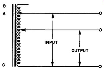
Fig. 40. Variable transformer that provides any voltage from zero to 15 volts
above the line voltage.
Variable transformers are sold on the basis of both KVA ratings and current ratings. The common range for non-industrial use extends from 0.165 kva at 1.25 amperes to 19 kva at 135 amperes.
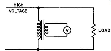
Fig. 41. A potential transformer connected to a high voltage line. The voltmeter
is generally calibrated to take into account the turns ratio of the transformer.
61. Instrument Transformers
The development of high-voltage alternating-current systems of transmission and distribution, necessitated the removal of various instruments from direct contact with the line circuits. Direct connection between high-tension lines and the devices on the front of the switchboard must be completely avoided. By using instrument transformers, the possibility of personal injury is minimized.
Transformers used for measuring high voltages at low current in this manner are known as potential transformers.
It is frequently necessary to meter large currents in circuits of moderate voltage. To avoid the expense and difficulty of carrying heavy leads to the switchboard, current transformers are used.
Potential transformers are generally operated under fixed conditions of applied voltage, frequency, and the number and character of the instruments in the secondary circuit. They are precision instruments and are more permanent than the instruments they operate. Figure 41 illustrates the connection method of a high voltage line, through a potential transformer, to the voltmeter.
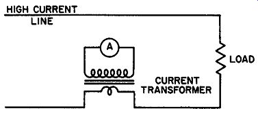
Fig. 42. The current transformer positioned to determine current flow in
a heavy-duty circuit.
Current transformers are sometimes called series transformers because of the way they are connected in the line (see Fig. 42) . When a current transformer is in use, it is important that the secondary winding be kept closed (i.e., the instrument must not be disconnected). If the secondary is open, there will be no de magnetizing effect due to the secondary flux and, as the primary current is fixed by the load on the line, the total flux may rise to a high value. This tends to increase the iron losses to such an extent that the insulation may be injured by the heat. At some subsequent time, this may result in insulation puncture even for a moderate voltage. In addition to this, the secondary voltage may be very large because of the high primary current. This may lead to damage of the secondary insulation. Also there is the possibility of severe shock from the secondary terminals.
62. Saturable Reactors
Although the words saturable reactor imply a single coil, most saturable reactors are really two-winding devices. The inductance of a choke or reactor is a function of the degree of core saturation, as well as the number of turns and type of core material. In a saturable reactor, a d-c winding that is distinct from the main reactor, governs the extent to which the core is saturated. A typical core and winding configuration is shown in Fig. 43. Al though the design of an efficient saturable reactor requires a thorough understanding of the principles of iron-core chokes carrying direct current, a general understanding of the action can be realized on a qualitative basis.
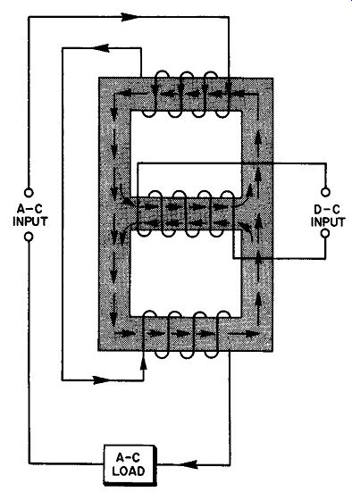
Fig. 43. A saturable re actor configuration.
The presence of a d-c winding suggests that ac flowing in the coils on the same core might induce a current in the d-c winding by normal transformer action. This would represent an appreciable loss of power under certain circumstances. To avoid induction from the ac into the d-c coil, the core and winding directions are arranged so that the a-c fields in the portion of the core on which the d-c winding appears tend to cancel each other. The arrows in Fig. 43 indicate the instantaneous directions of the fields in the center leg of the shell. The total field due to the ac has the same direction in all parts of the large rectangle of the shell, and the fields due to the individual a-c coils have opposite directions in the core section that carries the d-c winding.
Operationally, the magnitude of the direct current is controlled by a rheostat or potentiometer. With no current in the d-c winding, the inductance of the a-c section is maximum. Hence, the inductive reactance is also at its highest value. As the d-c increases, the core saturates more easily, and the inductance and reactance decrease as well. Thus, a saturable reactor is suitable wherever there is a need for an adjustable reactor. For example, the power provided to operate a load may be varied, by changing the inductance of a saturable reactor in series with an a-c power source and the load.
Saturable reactors distort the a-c waveform applied to the load.
Their use is limited, therefore, to applications in which waveform is of no importance.
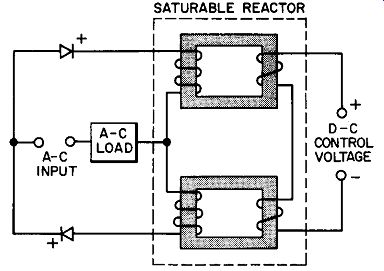
Fig. 44. Regenerative magnetic amplifier in which the load is an a-c operated
device or devices.
63. Self-saturating Saturable Readers
When small changes in the d-c control current can produce larger changes in the a-c load current, amplification results. This action is encountered in magnetic amplifiers. Appreciably more gain may be realized, however, by employing some form of regenerative feedback. Figure 44 shows one form of a regenerative saturable reactor, generally termed a self-saturating type.
An additional control winding feeds back a portion of the alternating-current output, by rectification of the load current.
With regeneration, the rectified load current flows through the feedback wiring, so as to aid the d-c control current, thereby pro viding more gain than is possible with the simpler form of saturable reactor. An increase in gain obtained this way, unfortunately, is also associated with a rise in response time and a decrease in linearity. Often, compared to the advantages that result from the augmented gain, these factors are unimportant. In applications where response time and linearity are important considerations, degenerative rather than regenerative feedback must be used. As in vacuum tube and transistor amplifiers, by introducing degeneration, linearity is improved; but the gain is reduced.
64. Voltage-regulating Transformers
Power transformers used in radio receivers, television sets, and other similar constant-load devices are generally not equipped for regulating voltage. In other types of equipment, such as class-B modulators, the load current may swing over an extremely wide range, and tend to produce serious fluctuations in the output voltage of the power supply. Electronic voltage regulators for the heavy d-c load found in even a medium-power class-B system are difficult to build and extremely costly. In such cases, voltage regulating transformers may be employed. Figure 45 illustrates the fundamental circuit involved in the applications of voltage-regulating transformers to a d-c power supply intended for varying loads.
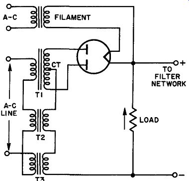
Fig. 45. Voltage-regulating transformers in a d-c power supply. T1 is the
main power transformer. T2 and T3 are matched voltage regulating transformers.
The secondary coils of both regulating transformers (T2 and T3) are in series with the load current from the output of the power supply. Should the load current suddenly increase, the flux density in these transformers rises, bringing them closer to saturation.
This reduces the primary inductance, hence, the inductive reactance, so that the voltage applied to the primary of the main power transformer increases. Thus, the secondary voltage, which tends to drop because of the increasing load current, is brought back to its initial value by the increased primary voltage.
The output of the regulating transformers must be eliminated, hence, the primaries of T2 and T3 are connected in series-opposing, so that these voltages cancel. (Series opposing is indicated in Fig. 45.) If cancellation is not perfect, an a-c ripple may be introduced in the power supply output, since the rectifier tube is not associated with the regulating circuit. A successful system of this kind depends upon perfectly matching both transformers.
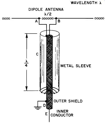
Fig. 46. A simple balancing device or balun.
65. Balancing Transformers (Baluns)
The need for balancing transformers arises most often in coup ling radio-frequency transmission lines to either transmitting or rece1vmg antennas. If a symmetrical centered antenna is connected to a balanced transmission line, such as in a parallel conductor open wire system, the inherent balance of the entire arrangement is not upset. Remember that the absence of radiation from a transmission line-an important requisite of an efficient antenna network--occurs because of cellation of r-f currents that flow down one wire and up the other in the transmission line.
For example, if a coaxial cable is used to feed the center of a half-wave transmitting antenna, unless balancing precautions are observed, radiation from the line will occur. This is understandable when we consider that the outer sheath of the coaxial cable is a shield that does not allow the radiation from the inner conductor to reach the skin-effect r-f flowing along the outside of the sleeve.
Without this cancellation, radiation takes place from the sleeve, with consequent loss of power transferred to the antenna.
Balancing the system involves inserting a balancing device commonly known as a balun (balance to unbalance). The simplest form of balun is shown in Fig. 46. This consists of a metallic sleeve fitted over the transmission line, and short-circuited to the coaxial shield at the bottom end. The sleeve length is made quarter-wave for the frequency to be transmitted.
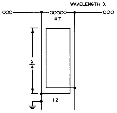
Fig. 47. A series-parallel balun arrangement used to match a balanced line
to an unbalanced line. Such a balun also offers an impedance transformation
of 4:1.
The input impedance of a short-circuited quarter-wave section approaches infinity. This characteristic is an important factor in the performance of the balun. The explanation of balun operation is somewhat easier to understand if we consider the voltage applied from the balanced antenna side, as would be the case if the antenna were for receiving purposes. This explanation is equally valid for transmitting antennas. Consider a voltage applied to A and B at the top of the line. The two halves of the antenna attempt to establish equal peak voltages, with respect to ground potential, at these points, since both halves are symmetrical with respect to ground. This appears impossible, since the extension of A (i.e., D) is grounded. The sleeve C may be considered an extension of the outer shield of the coaxial cable D; but the impedance across A and C is extremely high (approaching infinity) because this is a short-circuited quarter-wave section. Thus, sleeve C acting as an extension of D remains at ground potential, leaving A free to take on any potential the antenna delivers to it. It is clear, then, that the peak potentials across A and B can deviate from ground potential by equal amounts, despite the electrical continuity between A and D. A second form of balun may take on a coil as well as a linear form. Transmission lines (each one quarter wavelength as shown in Fig. 4 7) are connected in parallel at one end and in series at the other. The transmission lines are balanced with respect to ground at the series end (top in Fig. 47). One side of the line at the other end may be grounded because the two ends are decoupled by the short-circuited quarter-wave (or any odd multiple of a quarter-wave) section. At the series-connected end, the line will match an impedance equal to twice the characteristic impedance of the lines used. At the parallel-connected end, there will he an impedance match to one-half the characteristic impedance of the lines. Hence, the impedance transformation from parallel end to series end is 1:4. This is a very practical way to match a 300-ohm balanced line to a 75-ohm unbalanced coaxial line.
66. QUIZ
1. How does an autotransformer differ from a standard form of transformer? What are its advantages and disadvantages?
2. Draw a diagram showing how an autotransformer would be connected between an a-c line and a load to obtain step-up action.
3. Explain the salient requirements for a current transformer and for a voltage or potential transformer.
4. With the aid of a diagram, explain how a saturable reactor would be used as a magnetic amplifier.
5. Draw a circuit diagram showing how a saturable reactor would be connected with one winding providing degenerative feedback.
6. How does a voltage-regulating transformer operate? Explain in detail.
7. Describe a sleeve type of balun and explain its operation.
8. Repeat this procedure for a linear series-parallel balun.