AMAZON multi-meters discounts AMAZON oscilloscope discounts
An oscillator can be described in simple terms as an alternating current generator. Where only low frequencies are required, as in mains electricity for example, rotating machines offer a straightforward solution and can also operate at high power levels. In electronic circuits where very much higher ac frequencies are required, these are provided by oscillator circuits. They fall broadly into three types: resonant -frequency oscillators, crystal controlled oscillators, and phase-shift oscillators.
RESONANT-FREQUENCY OSCILLATORS
Resonant-frequency oscillator circuits are based on the particular property of an inductance (L) and an associated capacitance (C) to exhibit resonance whereby the current flowing in the circuit will oscillate from positive to negative in a sinusoidal manner at a frequency determined only by the values of L and C. The demonstration circuit shown in Fig. 18-1 illustrates the basic mode of working such a circuit.
In the initial state, with the switch in position, there is a steady current flowing through the coil but with no appreciable voltage, and so the capacitor remains uncharged. Movement of the switch to position 2 puts a large negative bias on the gate of the FET so that the drain current is cut off.
The resultant collapse of magnetic flux in the coil opposes the charge, so that current continues to flow into the capacitor, charging it up. Voltage across the capacitor can only increase at the expense of decreasing current, however, so a point is reached where the current falls to zero and the voltage is a maximum.
At this point, the capacitor starts to discharge, generating a current in the reverse direction, and with falling voltage. This continues until the voltage has dropped to zero, corresponding to maximum reverse current.
Capacitor
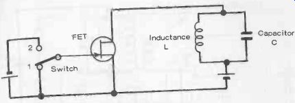
Fig. 18-1.
Demonstration circuit for LC oscillator.
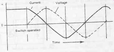
Fig. 18 2. Cycle of operation of LC oscillator. Switch operated Time
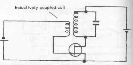
Fig. 18-3. Self -oscillating oscillator circuit.
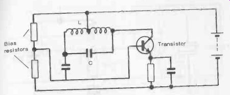
Fig. 18-5.
Practical Hartley-oscillator circuit.

Fig. 18-4. Two basic oscillator circuits.
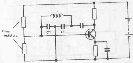
Fig. 18-6. Practical Colpitts-oscillator circuit.
The whole of the energy stored in the LC circuit is now returned to L but with reverse polarity.
Consequently, the voltage starts to increase in a negative direction, with the current decreasing, ending up with the capacitor charged in the reverse direction (maximum negative voltage) when the current again reaches zero. The circuit now starts to rse again in a positive direction with falling negative voltage to complete a full cycle of oscillation, as shown in Fig. 18-2. The cycle of operation is repeated over and over again at a frequency given by 1/2 ir x VLC Theoretically, at least, with an ideal inductance and an ideal capacitor, both having no electrical resistance, the original store of energy is ex changed indefinitely, i.e., oscillation will continue indefinitely in a sinusoidal manner with no further energy fed into the circuit (the original source of battery energy is switched off once the switch is moved from position 1 to position 2). In a practical circuit, however, there will be some resistance present, which will produce a gradual decay or damping of the amplitude of the oscillators (i.e., reduction in maximum voltage and current values).
The degree of damping present is dependent on the ratio of reactance to resistance in the LC circuit, or Q, as it is termed.
The lower the value of Q, the greater the damping present.
If the Q is as low as 1:2, the circuit is critically damped and will not oscillate at all. In other words, if conditions are right for the LC circuit to start oscillating, this will be damped out completely in the first cycle. Equally, the higher the Q, the greater the length of time oscillation will continue. However, in a practical oscillator circuit, some energy must be supplied to the circuit to keep it oscillating, i.e., to replace the energy dissipated in the resistance present in the circuit. Also, this supply of energy needs to be provided automatically in a practical circuit. Figure 18-3 shows how the original demonstration circuit can be modified to provide just this.
Here, the small coil inductively coupled to L generates a voltage exactly synchronized with the sinusoidal voltage generated in the LC circuit. The value of this voltage will depend on the number of turns in the small coil and how closely it is coupled to L-both being adjustable features in design. The induced voltage can, however, work with or against the voltage in the LC circuit. In other words, it will only work if the coil is connected one way. If the coupling is close, and the coil is connected the right way, such a circuit can be self -oscillating started up by random electron movements.
PRACTICAL LC OSCILLATORS
The basic requirements for a practical resonant -frequency or LC oscillator are thus an oscillatory circuit (L and C), associated with some means of maintaining oscillation (usually some form of amplifier such as a transistor, FET, or op-amp).
Two basic methods of doing this, using a transistor as the maintaining amplifier are shown in Fig. 18-4. In the first (A), the LC circuit is tapped on the inductive side. This is the basis of the Hartley oscillator.
In the second (B), the LC circuit is tapped on the capacitive side. This is the basis of the Colpitts oscillator. Practical circuits for these two important types of oscillators are shown in Figs. 18-5 and 18-6, respectively.
CRYSTAL-CONTROLLED OSCILLATORS
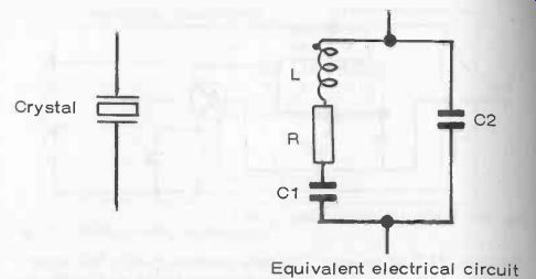
Fig. 18-7. Electrical circuit equivalent of a crystal.
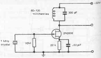
Fig. 18-8. 1 MHz crystal oscillator.
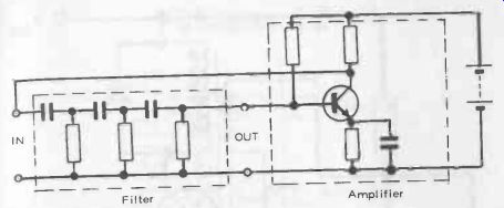
Fig. 18-9. Phase-shift oscillator based on filter circuit.
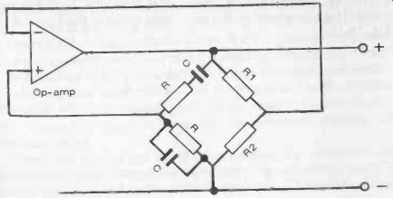
Fig. 18-10. Wien-bridge oscillator.
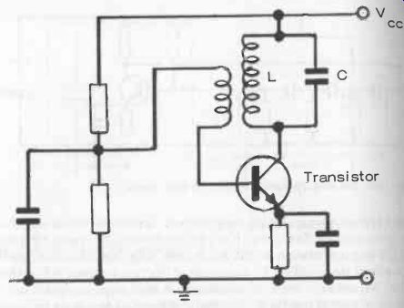
Fig. 18-11. Basic resonant circuit oscillator with transistor amplifier
A quartz crystal with electrodes planted on opposite faces, is the electrical equivalent of an inductance (L), resistance (R), and capacitance (C1) in series, with a much larger capacitance (C2) across them, see Fig. 18-7. It is, in fact, a complete LC circuit with a specific resonant frequency which may range from a few kHz to several MHz, depending on the crystal type, size, how it is cut and how it is mounted.
It also has the characteristic of a high Q with good stability, making it a most useful device to base an oscillator circuit around. It is also a more or less standard choice for a fixed frequency oscillator.
A whole variety of such circuits are possible. A basic configuration is shown in Fig. 18-8 where the active device is an FET.
It should be noted that, although a tuned circuit (LC combination) is included, the oscillator frequency is determined essentially by the resonant frequency of the crystal and not by the rest of the circuit. The tuning of the LC circuit can in fact, be relatively broad around this frequency, the crystal providing stabilized oscillator at a specific frequency.
The frequency of a crystal-controlled oscillator can be adjusted within very narrow limits (usually less than 5 parts in 10,000) by means of a variable capacitor connected across it. However, since crystals are simple, inexpensive devices which can plug into a socket, a change of crystal is usually the simplest method of frequency adjustment.
It is possible to produce an oscillator on the tuned-circuit principle by employing resistors instead of inductances. Basically, such circuits are filter networks (cascaded RC combinations), associated with an amplifier.
A three-stage RC filter circuit is needed to provide a total phase difference of 180 degrees between current and voltage, with a small loss matched by the gain of the amplifier. A basic circuit of this type is shown in Fig. 18-9, using a transistor for the active element. A basic requirement for such a circuit to work is that the input to the amplifier must be at least 11 Beta times the output in strength, where Beta is the gain of the transistor. This generally calls for the use of a transistor with a current gain of the order of 50 or better.
A particular advantage of phase-shift oscillators is that they can readily be varied in frequency over a wide range, using three variable capacitors, ganged together and varied simultaneously.
Their most useful working range is from a few Hz to hundreds of kHz. At higher frequencies--in the MHz range and above-they are generally inferior to resonant-circuit oscillators.
BRIDGE OSCILLATORS
One other type of oscillator worth describing is the Wien-bridge oscillator (another phase -shift type) where a balanced bridge is used as the feedback network, see Fig. 18-10. To work, the loop gain must equal unity and must have zero phase. This is generally given by suitable selection of resistor values so that R2/(R1 + R2) is less than 1/2.
The frequency of operation with this type is the frequency of the balanced bridge, or 1/2 pi RC.
Note that both the two resistor values and capacitor values on the left-hand side of the bridge are identical. The frequency of the oscillator can be changed by using different values for R, or, alternatively, for a variable-frequency oscillator, the two capacitors are replaced by ganged variable capacitors of identical value, varied simultaneously.
The majority of oscillator circuits, however, are based on resonant circuit or LC combinations of conventional form with a close-coupled second coil to promote self-oscillation. A basic circuit of this type is shown in Fig. 18-11.