1. Introduction--Prior to the use of embedded wire wound resistors, wire was wound on a porcelain rod or asbestos covered metal tube without any protection for the wire from corrosive or oxidizing effects of the atmosphere in which it was operated.
As resistors became more widely used the need for improvement in design and construction became obvious.
Early research and experiment indicated the necessity for manufacturing resistors capable of dissipating more heat energy, dissipating it faster and thereby making it possible to reduce the unit size.
Results of tests made were not at first fully appreciated nor were the difficulties fully and immediately overcome. Time and experience gradually showed that there are four basic elements that are of prime importance to satisfactory operation of a wire-wound resistor.
They are the core, the terminals, the resistive conductor, and the coatings.
2. Ceramic Core---Cores of every known description were tried with refractory ceramic cores always showing up best. Properly made and vitrified, they withstand shock and vibration, resist penetration of moisture and provide an adequate medium for the dissipation of heat.
There are many industrial ceramics with widely varying characteristics. Among the more important characteristics, insofar as they affect resistor performance, are mechanical strength, high density, and good thermal conductivity. Thermal expansion and contraction of the ceramic core must be properly correlated with the corresponding thermal properties of the other components of a complete resistor. The ceramics made for Vitrohm must possess all of these qualities, not perhaps to the fullest degree in any one particular, but to the greatest degree possible in all particulars.
The Vitrohm resistor ceramic core in the initial stage of manufacture, consists of finely ground powders which are thoroughly mixed with a binder. The mixture is formed into pugs~ under high pressure, in a pug mill, Figure 6-1. The pugs are then placed in an extruding machine, Figure 6-2, which shapes the pugs, in an extruding die, into hollow tubes about six feet long. The tubes are supported on steel mandrels to preserve their uniformity of shape and the accuracy of inside and outside dimensions. After oven drying the long tubes are cut to the required lengths, placed on racks, and then vitrified in long, gas-fired, conveyor, tunnel kilns, Figure 6-3. Kiln temperatures are automatically controlled from start to finish.
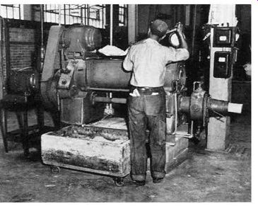
Figure 6-1. The refractory material is mixed and "de-aired" in this
automatically controlled pugging machine.
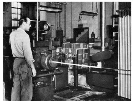
Figure 6-2. Long tubes of refractory material are extruded from hydraulic
presses. Note extreme precautions to insure straight cylindrical tubes.
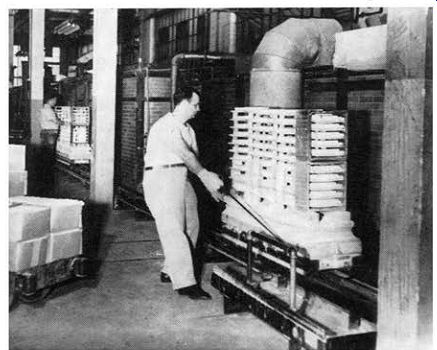
Figure 6-3. Extruded tubes, dried and cut to length, are fired for vitrification
in this specially-designed high temperature con trolled kiln.
On completion of the firing process the refractory tubes which may he cylindrical, oval in shape, cylindrical with flatted sides, or in other shapes, depending on the type of resistor, are segregated by size, length and general type. The tubes then undergo a thorough inspection that includes gauging of inside and outside diameters, eccentricity and longitudinal camber. Inspection also includes examination of tube surfaces to assure a smooth winding area. Further checks to determine that the proper degree of vitrification has been reached include a sampling test for porosity and an expansion check on an interferometer. The approved refractory core is then ready for use in the production of Vitrohm resistors.
3. Terminals--The terminals to he affixed to the refractory tubes are especially chosen to insure proper expansion and adhesion to the enamel and ceramic core.
Most of the terminals used on Vitrohm resistors are handed to the tube by spot welding to insure a uniformly tight and positive adherence to the tube, eliminating any possibility of shifting in the firing process.
4. Resistive Conductor--The tube, with its terminals attached, is then ready for the winding operation. The resistor to he wound is centered in the winding machine.
Directly below is located a lead screw, preselected to provide the proper winding pitch for the particular resistor being wound. The pitch is the spacing or number of turns of wire per inch of core length.
The alloy resistance wire, also preselected as to alloy and gauge, is fed from a spool over an automatic tension device and a guide, and attached to one end terminal. The winding machine is then started and the lead screw moves the guide along the tube, winding the resistance wire uniformly on the core.
With two terminal resistors only one winding is used.
On some tapped resistors or multi-section units, different wire sizes, alloys, or winding pitches may be used for each step.
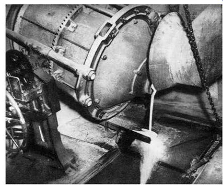
Figure 6-4. Vitrohm enamel being fritted. White hot, the vitreous enamel is
poured into a cold bath to break up the mass into small particles.
The correct winding is obtained either by using a turns counter, or by continuously balancing the winding against a master in a bridge circuit. The resistor is checked for resistance tolerance and all resistor wire to-terminal joints are then spot welded. The resistor is now ready for the enameling process.
5. Coating--The vitreous enamel is prepared by weighing out the proper ingredients and fritting the mixture, Figure 6-4. The frit is then ground, Figure 6-5, to a fine powder; the fineness of the powder is checked by sifting it through a bank of sieves, and the residue on each sieve is then rechecked. The enamel powder is then suspended in a liquid to obtain the proper consistency for coating the resistor. Each batch of enamel is checked for its expansion characteristics on an interferometer, Figure 6-6.
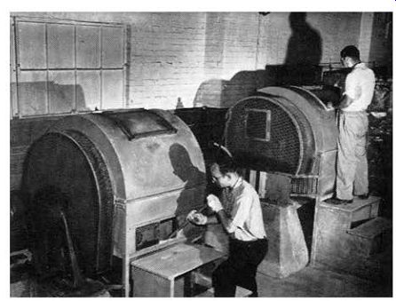
Figure 6-5. These revolving "ball mills" grind the frit to the exact
fineness needed to produce perfect Vitrohm (vitreous enamel).
After the resistor has been completely coated with enamel, except for the upright portion of the terminals, it is placed in a rack and the enamel is allowed to dry.
Then the bore and ends of the core are brushed to remove any enamel from these surfaces before the firing operation. Precautions are also taken to prevent the enamel from adhering to the exposed portion of terminals.
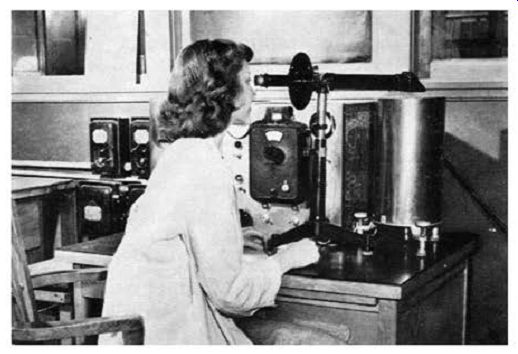
Figure 6-6. Vitreous enamel being measured by interferometer method for coefficient
of thermal expansion, melting point and annealing point.*
*This particular interferometer was one of the first built by the U. S. Bureau of Standards.
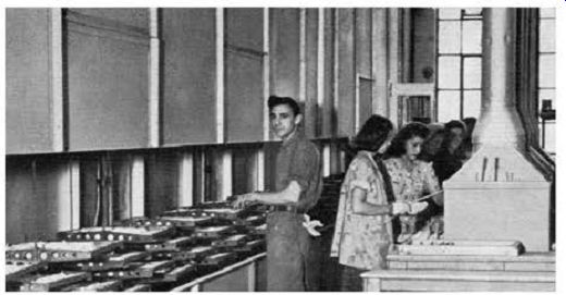
Figure 6-7. Resistors passing through the Enameling furnace where the Vitrohm
enamel coating is vitrified.
The resistor is then placed on a rod along with many others and the rod is suspended on a conveyor belt or rack that travels at a uniform rate through the enameling furnace, Figure 6-7. The long conveyor furnaces used in the manufacture of Vitrohm resistors have a pre-heat section, a high-heat section and a post-heat section. In this way the resistor is slowly brought up to firing temperature and gradually cooled to avoid stressing the resistor core or enamel. When the resistor reaches the center of the conveyor furnace, the temperature is such that the Vitrohm enamel becomes vitrified. Furnace temperatures are automatically controlled, recorded, and maintained between very close limits to insure the complete vitrification of the enamel.
After the resistor leaves the furnace, the terminals are cleaned. Some types of terminals are tinned while others are equipped with screws, nuts, bolts, lugs, or other hardware, as specified by the customer.
6. Inspection--The resistor is next checked for resistance value and adherence to tolerance limits. It is then marked for identification and resistance value.
After a final inspection to assure full conformity with the manufacturing or customer specifications for that particular resistor, the unit is carefully packed for shipment.
7. Quality Control--The resistor manufacturing process outlined in previous paragraphs appears to he relatively simple hut actually is quite complex. Uniformly high quality can he assured only by constant laboratory testing of all raw materials and finished components, as well as by close control over all manufacturing processes. Several of these tests and controls are indicated in the accompanying photographs.
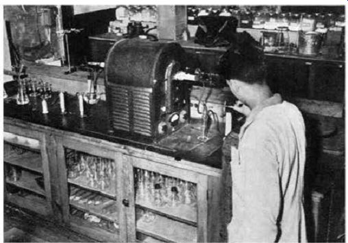
Figure 6-8. A test length of resistance wire is being processed in the combustion
furnace to determine carbon and sulphur con tent and insure accuracy of alloy
formula.
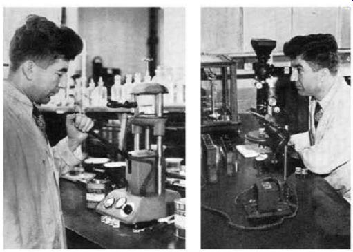
Figure 6-9. Minute pieces of metal samples, imbedded in plastic mounts, are
microscopically studied for grain and crystal structure.
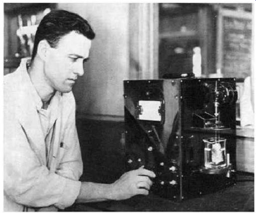
Figure 6-10. Electro-chemical analyzer checks metals and all incoming raw
materials for conformity with specifications to in sure uniform quality.