Conversion Factors
To find the unknown quantity (middle column) multiply the known value (left column) by the multiplier factor (right column)
Known Power
Unknown Multiplier Factor
Known
Area
Unknown Multiplier Factor
Known
Length
Unknown Multiplier Factor
Known
Energy
Unknown Multiplier Factor
Miscellaneous
Known Unknown Multiplier Factor
------------ Drill Sizes For Machine Screws
------------ Gauges for Wire, Sheet and Twist Drills
----------- Electrical, Mechanical and Heat Equivalents
----------- Temperature Conversion Tables
Read the known temperature in the column marked with an asterisk. Corresponding temperature in degrees Centigrade will be found in the left hand column. The corresponding temperature in degrees Fahrenheit will be found in the right hand column.
----------------- Full Load Motor Currents
All motor currents given below are approximate, based on average values as listed by the National Electrical Code. The table can be used for estimating purposes but is not intended for use in the selection oE overload relays. As motor characteristics vary somewhat dependent on the particular manufacturer, variations oE ± 10% oE the values listed below may he expected.
FULL LOAD CURRENT IN AMPERES A.C.
Induction Type Motors, Squirrel Cage and Wound Rotor
*For full load current of 208 and 200 volts motors, increase corresponding 230-volt motor full load current by 10 and 15 percent respectively,
**On two-phase (4-wire) motors, the amperes carried by the common conductor is 1.41 times value given.
***For full load currents of 208 and 200 volt motors, increase. the corresponding 220-volt motor full load current by 6 and 10 percent respectively.
Where k = elastic constant, m = mass, p = period of vibration, s= distance, t = time Mean velocity, V = ~ t
Instantaneous velocity, v ds dt A
. v-v0 dv ccelerat10n, a = -- = -
t dt when v0 = 0 v = at s = ½ at 2
Acceleration of gravity, g = 32.16 ft. per sec. per sec.
g = 980.2 cm. per sec. per sec.
mv^2 Centrifugal force = -r where r = radius of path
Displacement of spring, s = Fk mv-mvo
Force, F = ---- = ma t
Momentum = mv dv m dt Period of vibration, p = 2 pi vkm
Power, P = W = FV
Weight (force of gravity) = mg
Work (energy), W = Fs = mas = ½ mv^2
ELECTRICAL ANALOGS
Where C = capacity, L = inductance, p = period of oscillation, Q = charge, t = time Current, I
=dq dt Q t
Condenser charge, Q = EC El
electromotive force, _j = t di e = L -
Period of oscillation, p = 21ry CL P = EI W = EQ = Elt = ½ Ll2
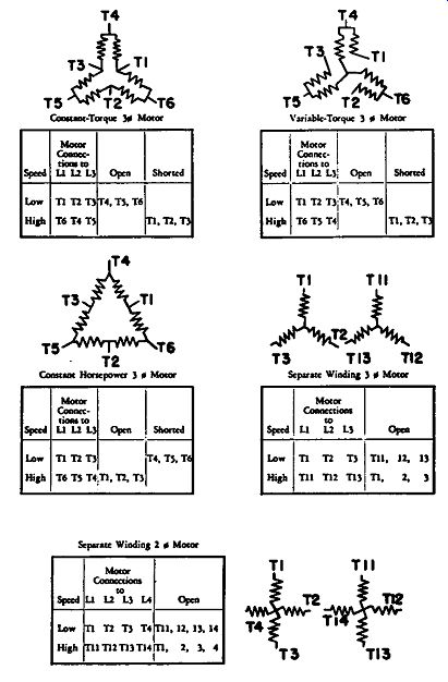
Symbols For Power, Control and Measurement.
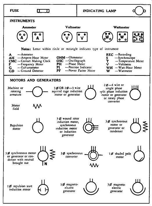
------- Symbols For Power, Control and Measurement.
-------------
Symbols For Power, Control and Measurement.
==============
BIBLIOGRAPHY AND REFERENCES
Standards
1--American Society for Testing Materials-Metallic Materials for Electrical-Heating, Electrical Resistance and Electrical Contacts (with related information). address: 1916 Race Street, Philadelphia 3, Pa.
2-- National Electrical Code, Pamphlet .No. 70, 1956.
address: .National Fire Protection Association, 60 Batterymarch Street, Boston 10, Mass.
3--National Electrical Manufacturers Association Standards for Industrial Control, Pub. No. ICl, May 1954 address: 155 East 44th Street, New York 17, N.Y.
4--Standard Handbook for Electrical Engineers, Knowlton, A. E., 8th Edition 1949, Pub. by McGraw-Hill Book Company, Inc.
address: 330 West 42nd Street, New York 17, N. Y. 5-Underwriters' Laboratories, Inc. Standard for Industrial Control Equipment, uL 508.
address: 161 Sixth Avenue, New York 13, N. Y. Government Specifications
1-MIL-V-173 Military Specification-Coating-materials, moisture--and fungus resistant, for the treatment of communication, electronic, and associated electrical equipment.
2-MIL-D-3716 Military Specification-Desiccants ( actuated).
3-MIL-R-11 Military Specification-Resistors, fixed composition (insulated).
4-MIL-R-19 Military Specification-Resistors variable wire-wound ( low operating temperature).
5-MIL-R-22 Military Specification-Resistors variable I wire-wound power type).
6-MIL-R-26 Military Specification. Resistors, fixed, wire-wound, power type.
7-MIL-R-29 Joint Army-Navy Specification-Resist ors, external meter (high voltage, ferrule terminal type.)
8-MIL-R-93 Military Specification-Resistors, accurate, fixed, wire-wound.
9-MIL-R-94 National Military Establishment Specification-Resistors, variable, composition.
10-MIL-R-15109 (Ships) Military Specification-Resistors, and rheostats, shock proof Naval Shipboard use).
Articles
"Fixed and Variable Resistors in Ready-To-Build-In Forms," Electrical Manufacturing, October 1943.
"Resistors for Power Applications," H. F. Littlejohn, Jr. Electrical South, November and December 1946.
"Resistors Used in High-Current Control Applications," H. F. Littlejohn, Jr., Electrical Manufacturing, February 1948.
"Which Type of Resistor," The Instrument Maker, Jan. Feb. 1938.
"Three Design Considerations in Selecting Resistance Alloys," C. P. Marsden, Jr., Electrical Manufacturing, August 1948.
Books
Components
Handbook, John F. Blackburn, McGraw-Hill Book Co., Inc.
Control of Electric Motors, P. B. Harwood, John Wiley and Sons, Inc.