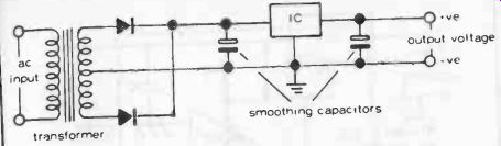
Fig. 1. Typical circuit for stepping down an ac voltage via a transformer
and rectifying it to produce a lower dc output.
Where a semiconductor circuit operating on low voltage dc is powered from the mains supply via a step-down transformer, voltage regulation is highly desirable in many circuits in order to en sure constant dc supply voltage. This can be provided by using zener diodes in associated circuitry. Exactly the same function can be performed by a single IC. A particular advantage is that such an IC can also incorporate internal overload and short-circuit protection which would call for numerous extra components in a circuit using discrete components.
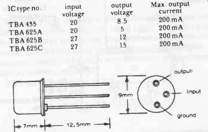
Fig. 2. TBA435 integrated circuit is enclosed in a TO-39 metal can shape
and looks like a transistor because it only has three leads.
A typical circuit is shown in Fig. 1, giving a rectified, positive dc voltage output from the center tapped secondary of the trans former. The same components can be used in mirror-image configuration to give a negative output voltage from the center tap (in which case the polarity of the two electrolytic capacitors must be reversed).
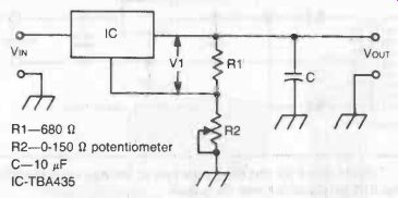
Fig. 3. Adjustable output voltage regulator circuit. The potential divider
formed by R1 and R2 following the IC enables the output voltage to be adjusted
via R2; otherwise the circuit is the same as Fig. 1. Alternatively this circuit
can be applied to a dc input: Note. Other IC voltage regulators can be used
and/or different input voltages, in which case different values of R1 and R2
may apply. As a general rule R2 needs to be about one-third to one-half the
value of R1.
Vout = R2 / R1 + 1G R2
Component values for this circuit with an input voltage of 18 volts are given in the figure.
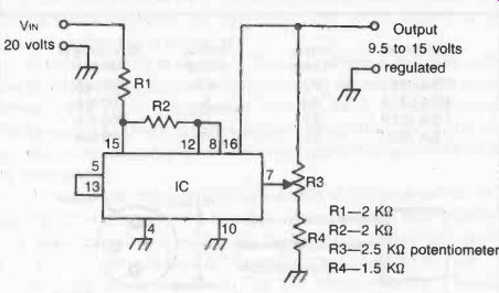
Fig. 4. Voltage regulator using the CA3097E integrated circuit array. This
provides 9.5 to 15 volts regulated output from a 20 volts dc input, the actual
output voltage being determined by the setting of R3.
Performance characteristics of a family of ICs designed as voltage regulators are given in Fig. 2. They are quite small devices in a TO-39 metal case with three leads-input, output and earth.
The earth or ground lead is internally connected to the case.
A circuit similar to that in Fig. 1, which uses the TBA435 chip is shown in Fig. 3.
There are numerous other simple voltage regulators which can be built from integrated circuit arrays (see Section 2) simply by "tapping" the appropriate leads to connect the individual components required into the complete circuit. An example is shown in Fig. 4, which is a regulator to provide an adjustable constant voltage dc output from an unregulated (and thus possibly variable) 20 volt dc input. It uses the transistors, diode and zener diode contained in the CA 3097E chip with a potentiometer and external resistor to complete the circuit. The actual output voltage can be adjusted from 9.5 to 15 volts by the setting of the potentiometer, with an output current ranging up to 40 mA, depending on the value of the output load.
Other simple voltage regulators can be based on op-amps.
A basic circuit is shown in Fig. 5. The reference voltage is set by the zener diode, the value of R1 being chosen to provide optimum zener current for the input voltage concerned.
The (regulated) output voltage is determined by the reference voltage (V ref) and the values of R2 and R3:
VOUT = V ref (R2 + R3 / R3 )
A circuit which provides a small difference between volts in and volts out is shown in Fig. 6. Using a PNP transistor it needs only about 1 volt to saturate the transistor, while adequate current is available for the regulating circuit using an NPN transistor.
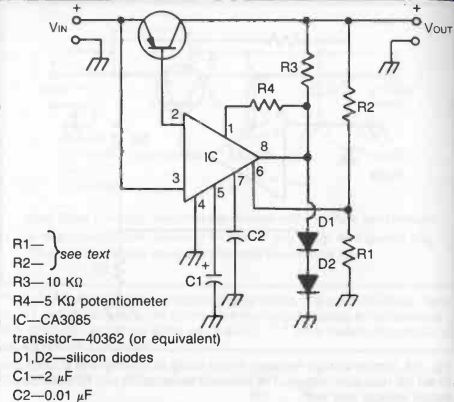
Fig. 6. Voltage regulator circuit incorporating a PNP transistor which gives
a difference between VIN and VOUT of about 1 volt (i.e., the voltage necessary
to saturate the transistor).
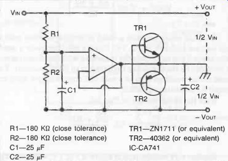
Fig. 7. This circuit gives a regulated split supply from any input voltage
from 5 to 36 volts.
The same circuit would need about 4 volts difference between input and output to maintain regulation.
With the circuit shown in Fig. 8-6, VOUT = 1.6 (R1 + R2) R1
Another very useful circuit is shown in Fig. 7, which provides a split supply from a single battery source. In other words it halves the input voltage while also producing a good degree of regulation of the two (plus and minus) voltage outputs. None of the component values is critical but R1 and R2 should be of close-tolerance type of equal value. Input voltage can range from 6 to 36 volts, when one half of the input voltage will appear between output + and 0, and the other between 0 and output - .