A variety of ICs are designed as speed regulators for small dc motors such as those used in portable cassette players, movie cameras, models and toys. The object is to "govern" the motor so that it runs at a constant speed, independent of variations in battery sup ply voltage and load on the motor. The TDA1151 is selected for the following circuits, having a maximum rating of 20 volts (which covers most model and other small dc motors), with an output current of up to 800 milliamps. It is a flat rectangular plastic package with three leads emerging from one end, and comprises 18 transistors, 4 diodes and 7 resistors in a linear integrated circuit.
In its simplest application it is used with a potentiometer (Rs) acting as a speed regulation resistance (and by which the actual motor speed is adjusted); and a torque control resistor (Rd which provides automatic regulation against load on the motor. Both these resistors are bridged by capacitors, although C2 can be omitted see Fig. 1. Component values shown are suitable for a 6 to 12 volt supply.
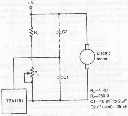
Fig. 1. Use of the TDA1151 linear integrated circuit as a speed regulator
for a small dc electric motor.
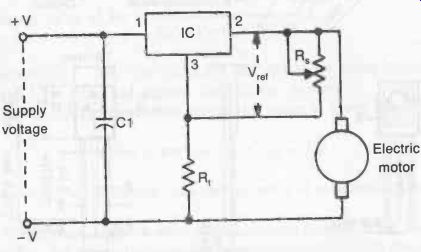
Fig. 2. Application circuit for the TCA600/610 or TCA900/910 motor speed
regulators. R is the speed regulation resistor (variable). R is the torque
control resistor. A suitable value for C1 is 0.1 F. A diode canoe added in
line 3 to provide temperature compensation as well.
A slightly different circuit is shown in Fig. 2, using a TCA600/900 or TCA610/910 integrated circuit. These have maximum voltage ratings of 14 and 20 volts respectively; and maximum current ratings of 400 milliamps for starting, but only 140 milliamps for continuous running.
Devices of this type work on the principle of providing a constant output voltage to the motor independent of variations of supply voltage, the value of this voltage being set by adjustment of R0. At the same time the device can generate a negative output resistance to compensate speed fluctuations due to variations in torque. This negative output resistance is equal to RT/K, where K is a constant, depending on the parameters of the device, viz:
IC K (typical) Vref I°
TDA1151 20 1.2 1.7 mA
TCA600/900 8.5 2.6 2.6 mA
TCA610/910 8.5 2.6 2.6 mA
The above also shows the reference voltage (Vref) and quiescent current drain (Id of the three ICs mentioned.
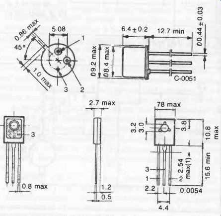
Fig. 3. Physical appearance of the TCA600/610 in a TO-39 metal can and the
TCA900/910 in a flat plastic package.
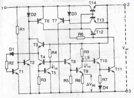
Fig. 4. Although small devices, these integrated circuits for motor speed
control are based on the complicated circuitry shown here.
The following relationships then apply for calculating suitable component values for these circuits:
R=KRM
where RM is the typical motor resistance.
Vref RT
Minimum value of Rs =
Eg- (Vref- loRT)
where Eg = back emf of motor at required or rated speed, and I° = quiescent current drain of the device.
Actual voltage developed across the motor is given by:
Volts (at motor) = RM IM + Eg
…where IM is the current drain by the motor at required or rated speed.
The physical appearance of these chips can be seen in Fig. 3, while Fig. 4 shows the complex internal circuitry within one of these chips.