AMAZON multi-meters discounts AMAZON oscilloscope discounts
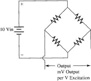
Load cells are made by combining a number of strain gauges in a common sensor that can measure changes in pressure. Since the individual strain gauges each change their resistance when they are deformed by strain, the load cell operation will look like a Wheatstone bridge circuit. When the pressure (load)-is applied to the load cell, the resistance of the bridge will change the amount of output voltage from the sensor. The figure (below) shows an example of the electrical diagram of a load cell (notice the similarity to the circuit of a strain gauge). The voltage used to supply power to the load cell (bridge) is called exciter voltage. The voltage that comes from the load cell as an output signal will be measured in millivolts (mV). When a load is applied to the load cell sensor, the amount of millivolt output will increase. The total amount of output signal that the load cell can produce is specified in terms of millivolt of output per volt of exciter voltage (mV/V). Typical output voltage is 2 mV - 3 mV per volt of excitation voltage. Typical excitation voltage is 5-10 volts dc. This means that most load cells are able to produce a maximum of 30 mV when fully loaded.
PREVIOUS: Introduction to Load Cells | NEXT: Troubleshooting Load Cells