| Home page Forum DAQ Fundamentals DAQ hardware DAQ Software Input Devices Data Loggers + Recorders Books Links + Resources |
AMAZON multi-meters discounts AMAZON oscilloscope discounts
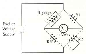 The
strain gauge must be connected to an electrical circuit for it to be useful.
The figure (left) shows an example of a two-wire strain gauge connected
to a Wheatstone bridge circuit. From this example you can see that the
strain gauge acts like one of the legs of the bridge. The typical resistance
for the strain gauge is 120 Ω. Resistor R2, is used to
balance all the resistance in the bridge. When this occurs and no force
is applied to the surface where the strain gauge is mounted, the voltage-out
signal will be zero. When a force is applied to the surface, it will deform
the metal that the strain gauge is glued to. At this time, the wire in
the strain gauge will also deform and the amount of resistance in the
wire will change. The change in resistance is proportional to the deformation
of the wire in the strain gauge, which means that the signal from the
bridge circuit will be somewhat linear due to the change in pressure.
You should notice that R2, can be adjusted at any point to
balance the bridge. If a small amount of pressure is applied to the strain
gauge when the circuit is balanced, it's called a preload. The formula
for calculating the voltage out from the bridge is:
The
strain gauge must be connected to an electrical circuit for it to be useful.
The figure (left) shows an example of a two-wire strain gauge connected
to a Wheatstone bridge circuit. From this example you can see that the
strain gauge acts like one of the legs of the bridge. The typical resistance
for the strain gauge is 120 Ω. Resistor R2, is used to
balance all the resistance in the bridge. When this occurs and no force
is applied to the surface where the strain gauge is mounted, the voltage-out
signal will be zero. When a force is applied to the surface, it will deform
the metal that the strain gauge is glued to. At this time, the wire in
the strain gauge will also deform and the amount of resistance in the
wire will change. The change in resistance is proportional to the deformation
of the wire in the strain gauge, which means that the signal from the
bridge circuit will be somewhat linear due to the change in pressure.
You should notice that R2, can be adjusted at any point to
balance the bridge. If a small amount of pressure is applied to the strain
gauge when the circuit is balanced, it's called a preload. The formula
for calculating the voltage out from the bridge is:
Vout = Vin ((R3/(R3+Rg)) - ((R2/(R1+R2))
This means that (R1/R2) = (Rg/R3) when the bridge is balanced.
Exercise:
A strain gauge is connected to a bridge circuit where R1 and R3 are 150 Ω resistors. The resistance of the strain gauge with no weight applied is 120 Ω. To what value should R2 be adjusted for the bridge to be balanced when no pressure is applied o the strain gauge?
Solution:
Since (R1/R2) = (RI/R3), this formula
can be manipulated to solve for R2.
R2 = (R1) x (Rg/R3)
R2 = (150 Ω) x (120 Ω/150 Ω)
R2 = 120 Ω
Exercise:
When a load of 10 psi is applied to a strain gauge in the previous problem, its resistance will change 20 Ω so that the total resistance of the strain gauge changes from 120 Ω to 140 Ω. If an input voltage of 10 volts is applied to the circuit, what will be the output voltage when the 10 psi load is applied to the strain gauge?
Solution:
Using the previous formula for voltage out:
Vout = Vin ((R3/(R3+Rg)) - ((R2/(R1+R2))
R1 = 150 Ω (given)
R2 = 120 Ω (calculated from prior problem)
R3 = 150 Ω (given)
Rg = 140 Ω (increased 20 Ω because of load placed
on strain gauge)
Vin = 10 volts
Vout = 10 volts ((150 Ω /(150 Ω + 140 Ω))
- ((120 Ω /(150 Ω +120 Ω))
Vout = 10 volts (9.28)
Vout = 0.728 volt
Gauge Factor
Gauge factor (GF) is the ratio of the amount of change in resistance to the change in the length (strain) along the axis of the gauge. The formula for calculating the gauge factor is:
GF = ((ΔR/R)/(ΔL/L)) = (ΔR/R)/ε
Notice that ΔL/L is identified as epsilon ε. Gauge factor is a dimensionless value, and the larger the value the more sensitive the strain gauge is. The gauge factor is provided with the strain gauge: typical values are 2-2.5.
Prev. Page: Types of Strain Gauges | Next Page: Pressure Transducers and Transmitters
Related pages: Load Cells | Flow Meters