AMAZON multi-meters discounts AMAZON oscilloscope discounts
1. Introduction
In Section 4.7 the principle of discrete-time control systems was introduced, these being control systems in which one or more inputs can change only at discrete instants of time and involve logic control functions. For example, the control system for an automatic drilling machine (FIG. 1) might be required to start lowering the drill when the workpiece is in position, start drilling when the drill reaches the workpiece and the workpiece is in position, stop drilling when the drill has produced the required depth of hole, retract the drill and then switch off and wait for the next workpiece to be put in position before repeating the operation.
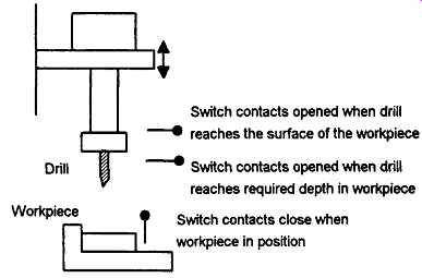
FIG. 1 An automatic drilling machine
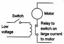
FIG. 2 Control circuit using a relay
For such control operations, what form might a controller have? We could wire up electrical circuits in which the closing or opening of switches would result in motors being switched on or valves being actuated. Thus we might have the closing of a switch activating a relay which, in turn, switches on the current to a motor and causes the drill to rotate (FIG. 2). Another switch might be used to activate a relay and switch on the current to a pneumatic or hydraulic valve which results in pressure being switched to drive a piston in a cylinder and so results in the workpiece being pushed into the required position. Such electrical circuits would have to be specific to the automatic drilling machine.
However, instead of hardwiring each control circuit for each control situation we can use the same basic system for all situations if we use a microprocessor-based system and write a program to instruct the microprocessor how to react to each input signal from, say, switches and give the required outputs to, say, motors and valves. Thus we might have a program of the form:
If switch A closes
Output to motor circuit
If switch B and C closed
Output to valve circuit
By changing the instructions in the program we can use the same microprocessor system to control a wide variety of situations.
This section, after considering the functions of logic gates, takes a look at the programmable logic controller (PLC). A PLC is a microprocessor-based system that uses a programmable memory to store instructions and implement functions such as logic, sequencing, timing, counting and arithmetic in order to control machines and processes and is designed to be operated by engineers with perhaps a limited knowledge of computers and computing languages.
Thus, the designers of the PLC have pre-programmed it so that the control program can be entered using a simple, rather intuitive, form of language. Input devices, e.g. sensors such as switches, and output devices in the system being controlled, e.g. motors, valves, etc., are connected to the PLC. The operator then enters a sequence of instructions, i.e. a program, into the memory of the PLC. The controller then monitors the inputs and outputs according to this program and carries out the control rules for which it has been programmed.
PLCs have the great advantage that the same basic controller can be used with a wide range of control systems. To modify a control system and the rules that are to be used, all that is necessary is for an operator to key in a different set of instructions. There is no need to rewire. The result is a flexible, cost effective, system which can be used with control systems which vary quite widely in their nature and complexity. The first PLC was developed in 1969. They are now widely used and extend from small self-contained units for use with perhaps 20 digital inputs/outputs to modular systems which can be used for large numbers of inputs/outputs, handle digital or analogue inputs/outputs, and also carry out proportional-integral-derivative control modes.
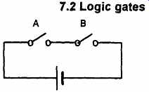
FIG. 3 An AND gate
2. Logic gates
Consider the control system (FIG. 3) where the water input valve to the domestic washing machine switched on if we have both the door to the machine closed, input signal A, and a particular time in the operating cycle has been reached, input signal B. There are two input signals which can be either yes or no signals and an output signal which can be a yes or no signal. The controller is programmed to give a yes output if both the input signals are yes and a no output when one or both of them are no.
These two levels may be represented by the binary number system with the on level being represented by 1 and the off level by 0. Thus, for FIG. 3, if inputs and input B are both 1 then there is an output of 1.
If either input A or input B or both are 0 then the output is 0. Such an operation is said to be controlled by a logic gate, in this case an AND gate.
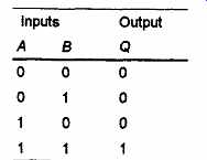
Table 1 AND gate
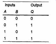
Table 2 OR gate
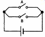
FIG. 4 OR gate
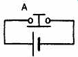
FIG. 5 NOT gate
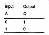
Table 3 NOT gate
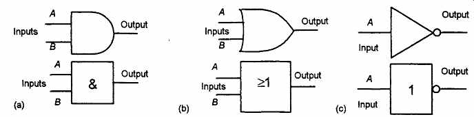
FIG. 6 Logic gate symbols: (a) AND, (b) OR, (c) NOT
The relationships between inputs to a logic gate and the outputs can be tabulated in a form known as a truth table. Thus for an AND gate with inputs A and B and a single output Q, we will have a 1 output when, and only when, A = 1 and B - 1. All other combinations of A and B will generate a 0 output. The truth table is given in Table 1.
An example of an AND gate is an interlock control system for a machine tool such that if the safety guard is in place, giving a 1 signal, and the power is on, giving a 1 signal, then there can be a 1 output and the machine will operate. If either of the inputs is 0 then the machine will not operate.
An OR gate is a system which with inputs^ and B gives an output of a 1 when /^ or 5 is 1. We can visualize the OR gate as an electrical circuit which has two switches in parallel (FIG. 4). When switch A or B is closed then there is a current. Table 2 is the truth table. An example of an OR gate is a conveyor belt system transporting finished bottled products to packaging where an arm is required to deflect bottles off the belt if either the weight is not within certain tolerances or there is no cap on a bottle.
A NOT gate has just one input and one output, giving a 1 output when the input is 0 and a 0 output when the input is 1. The NOT gate gives an output which is the inversion of the input and is thus often called an inverter. We can visualize such a gate as being an electrical circuit (FIG. 5) with a switch which is normally allowing current to pass but when pressed switches the current off. Table 3 is the truth table. An example of a situation where a NOT gate might be used is where a light has to come on when the light level falls below a set value.
This might be a light which comes on at night. When there is an input there is not an output.
Two forms of standard circuit symbols are in use for logic gates, one having originated in the United States and the other being an international form (IEEE/ANSI) which uses a rectangle with a symbol for the logic function inside it. FIG. 6 shows the symbols for the AND, OR and NOT gates.
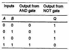
Table 4 NAND gate
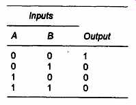
Table 5 NOR gate
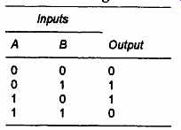
Table 6 XOR gate
Application ---- Logic gates are available as integrated circuit chips. For example, the integrated circuit 74LS21 has two 4-input AND gates in one 14 pin package (FIG. 10). The integrated circuit 74LS08 has four 2-input AND gates in one 14 pin package. The integrated circuit 74LS32 has four 2Hnput OR gates in one 14 pin package.
Gates can be combined to produce other relationships between inputs and outputs. Combining an AND gate with a NOT gate (FIG. 7) gives what is termed a NAND gate. Table 4 is the truth table.
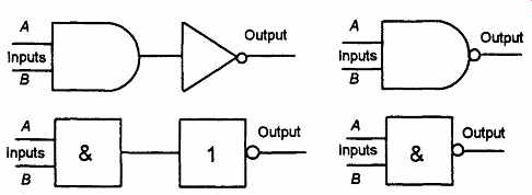
Fig. 7 NAND gate
Likewise, if an OR gate is combined with a NOT gate we obtain a NOR gate (FIG. 8) (Table 5), an exclusive OR (XOR) gate by a combination of OR and AND gates (FIG. 9) (Table 6).
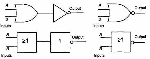
FIG. 8 NOR gate
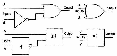
FIG. 9 XOR gate
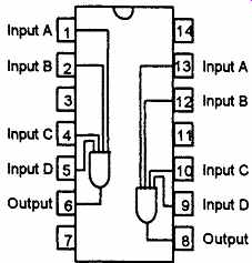
FIG. 10 74LS21 integrated circuit
Example:
What types of logic gates might be needed in the following control situations: (a) part of a chemical plant where an alarm is to be activated if the temperature falls below a certain level, (b) an automatic door is to open if a person approaches fix)m either side?
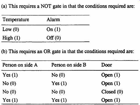
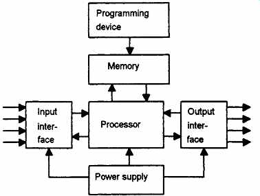
FIG. 11 The PLC system
3. PLC system
Typically a PLC system has five basic components. These are the processor unit, memory, the power supply unit, input/output interface section and the programming device. FIG. 11 shows the basic arrangement.
1. The processor unit or central processing unit (CPU) is the unit containing the microprocessor and this interprets the input signals and carries out the control actions, according to the program stored in its memory, communicating the decisions as action signals to the outputs.
2. The power supply unit is needed to convert the mains a.c. voltage to the low d.c. voltage (5 V) necessary for the processor and the circuits in the input and output interface modules.
3. The programming device is used to enter the required program into the memory of the processor. The program is developed in the device and then transferred to the memory unit of the PLC.
4. The memory unit is where the program is stored that is to be used for the control actions to be exercised by the microprocessor.
5. The input and output sections are where the processor receives information from external devices and communicates information to external devices. Every input/output point has a unique address in the system. The inputs might thus be from switches, as illustrated in FIG. 1 with the automatic drill, or other sensors such as photo electric cells, temperature sensors, flow sensors, etc. The outputs might be to motor starter coils, solenoid valves, etc. The input/ output channels provide isolation and signal conditioning functions so that sensors and actuators can often be directly connected to them without the need for other circuitry. Electrical isolation from the external world is usually by means of optoisolators (the term optocoupler is also often used) (FIG. 12). When a digital pulse passes through the light-emitting diode, a pulse of infrared radiation is produced which is detected by the phototransistor and gives rise to a voltage in that circuit. The gap between the light-emitting diode and the phototransistor gives electrical isolation but the arrangement still allows for a digital pulse in one circuit to give rise to a digital pulse in another circuit. Outputs are often specified as being of relay type, transistor type or triac type. With the relay type, the signal from the PLC output is used to operate a relay and so is able to switch currents of the order of a few amperes in an external circuit.
The relay not only allows small currents to switch much larger currents but also isolates the PLC from the external circuit. Relays are, however, relatively slow to operate. Relay outputs are suitable for a.c. and d.c. switching. They can withstand high surge currents and voltage transients. The transistor type of output uses a transistor to switch current through the external circuit. This gives a considerably faster switching action. It is, however, strictly for d.c. switching and is destroyed by overcurrent and high reverse voltage.
As a protection, either a fuse or built-in electronic protection are used. Optoisolators are used to provide isolation. Triac outputs, with optoisolators for isolation, can be used to control external loads which are connected to the a.c. power supply. It is strictly for a.c. operation and is very easily destroyed by overcurrent. Fuses are virtually always included to protect such outputs.
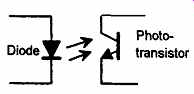
FIG. 12 Optocoupler
Application -------- The following are some examples of small PLCs.
With the Mitsubishi FX family of PLCs, the model FX1S is available with twelve 24 V d.c. outputs and relay type outputs, transistor type outputs, or triac type outputs. Thus, FX1S-10 MT-ESS/UL has six 24 V d.c. inputs and four transistor outputs, FX1S-10 MR-ES/UL has six 24 V d.c. inputs and four relay outputs.
The Toshiba T1 family of PLCs is likewise available in a wide variety of forms, e.g. with eight 24 D d.c. inputs, six relay outputs and two transistor outputs.
The Siemens Siematic S5 range of PLCs includes a ten input, six relay output model.
There are a wide range of PLCs commercially available. Small PLCs are generally in a single box (or, as sometimes termed, brick) and typical commercial forms might have 6, 8, 12 or 24 inputs and 4, 8 or 16 outputs. They are designed to be used close to the equipment being controlled. Systems with larger numbers of inputs and outputs are likely to be modular and designed to fit in racks. The number of inputs and outputs of a system can then be readily increased by adding more modules.
4. PLC programming
The basic form of programming used with PLCs is ladder programming.
As an introduction to ladder diagrams, consider the simple wiring diagram for an electrical circuit in FIG. 13(a). The diagram shows the circuit for switching on or off an electric motor. We can redraw this diagram in a different way, using two vertical lines to represent the input power rails and stringing the rest of the circuit between them. FIG. 13(b) shows the result. Both circuits have the switch in series with the motor and supplied with electrical power when the switch is closed. The circuit shown in FIG. 13(b) is termed a ladder diagram.
With the ladder diagram the power supply for the circuits is always shown as two vertical lines with the rest of the circuit as horizontal lines.
The power lines, or rails as they are often termed, are like the vertical sides of a ladder with the horizontal circuit lines like the rungs of the ladder. The horizontal rungs show only the control portion of the circuit, in the case of FIG. 13 it is just the switch in series with the motor.
Circuit diagrams often show the relative physical location of the circuit components and how they are actually wired. With ladder diagrams no attempt is made to show the actual physical locations and the emphasis is on clearly showing how the control is exercised.
Writing a program for a PLC using ladder programming is equivalent to drawing a switching circuit of the form shown in FIG. 13(b). FIG. 14 shows a simple ladder program. In drawing a ladder diagram, certain conventions are adopted:
1. The vertical lines of the diagram represent the power rails between which circuits are connected.
2. Each rung on the ladder defines one operation in the control process.
3. A ladder diagram is read from left to right and from top to bottom.
Thus, the top rung is read from left to right. Then the second rung down is read from left to right and so on. When the PLC is in its run mode, it goes through the entire ladder program to the end, the end rung of the program being clearly denoted, and then promptly resumes at the start. This procedure of going through all the rungs of the program is termed a cycle.
4. Each rung must start with an input or inputs and must end with at least one output, input devices being represented by two short parallel lines to represent switching contacts and output devices being represented by circles. The term input is used for a control action, such as closing the contacts of a switch, used as an input to the PLC. The term output is used for a device connected to the output of a PLC, e.g. a motor.
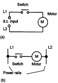
FIG. 13 Ways of drawing the same electrical circuit
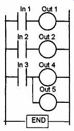
FIG. 14 A simple ladder program
5. Electrical devices are shown in their normal condition. Thus a switch which is normally open until some object closes it, is shown as open on the ladder diagram. A switch that is normally closed is shown closed.
6. A particular device can appear in more than one rung of a ladder.
For example, we might have a relay which switches on one or more devices. The same letters and/or numbers are used to label the, device in each situation.
7. The inputs and outputs are all identified by their addresses, the notation used depending on the PLC manufacturer. This is the address of the input or output in the memory of the PLC. For example, Mitsubishi PLCs precede input elements by an X and output elements by a Y and thus we have numbers such as X400 and X401 for inputs and Y430 and Y431 for outputs.
FIG. 15 shows some of the standard symbols used in ladder diagrams.
To illustrate the drawing of a ladder diagram rung, consider a situation where the starting of a motor output device depends on a normally open start switch being closed. Starting with the input, we represent the normally open switch by the symbol | |. This might be labeled with the address X400. The ladder rung terminates with the output, the motor, which is designated by the symbol O. This might be labeled with the address Y430. We thus have the ladder diagram shown in FIG. 16. When the switch is closed the motor is activated.
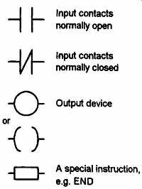
FIG. 15 Standard symbols
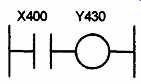
FIG. 16 An example of a ladder rung
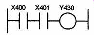
FIG. 17 An AND gate
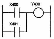
FIG. 18 An OR gate
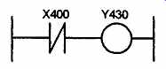
FIG. 19 NOT gate
4.1 Logic gates
Ladder rungs are frequently written to carry out logic functions. For example, consider a situation where a motor is started when two, normally open, switches have both to be closed. This might represent a machine tool motor which will not start until the power switch is on and the switch indicating the closure of the safety guard is on. This describes an AND logic gate situation. The ladder diagram starts with ||, labeled X400, to represent switch A and in series with it ||, labeled X401, to represent switch B. The line then terminates with O, labeled Y430, to represent the output. FIG. 17 shows the ladder rung.
FIG. 18 shows a situation where a motor is not switched on until either, normally open, switch A or switch B is closed. The situation is an OR logic gate. The ladder diagram starts with ||, labeled X400, to represent switch A and in parallel with it ||, labeled X401, to represent switch B. The line then terminates with O, labeled Y430, to represent the output.
FIG. 19 shows a NOT gate system on a ladder diagram. The input X400 contacts are shown as being normally closed. This is in series with the output Y430. With no input to X400, the contacts are closed and so there is an output. When there is an input, the contacts open and there is then no output. An example of a NOT gate control system is a light that comes on when it becomes dark, i.e. when there is no light input to the light sensor there is an output.
FIG. 20 shows a ladder diagram which gives a NAND gate. When the inputs to input X400 and input X401 are both 0 then the output is 1.
When the inputs to input X400 and input X401 are both 1, or one is 0 and the other 1, then the output is 0. An example of a NAND gate control system is a warning light that comes on if, with a machine tool, the safety guard switch has not been activated and the limit switch signaling the presence of the workpiece has not been activated.
FIG. 21 shows a ladder diagram of a NOR system. When input X400 and input X401 are both not activated, there is a 1 output. When either X400 or X401 are 1 there is a 0 output.
FIG. 22 shows a ladder diagram for an XOR gate system. When input X400 and input X401 are not activated then there is 0 output.
When just input X400 is activated, then the upper branch results in the output being 1. When just input X401 is activated, then the lower branch results in the output being 1. When both input X400 and input X401 are activated, there is no output. In this example of a logic gate, input X400 and input X401 have two sets of contacts in the circuits, one set being normally open and the other normally closed. With PLC programming, each input may have as many sets of contacts as necessary.
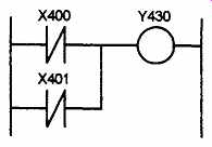
FIG. 20 NAND gate
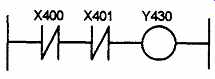
FIG. 21 NOR gate
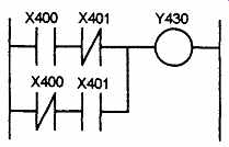
FIG. 22 XOR gate
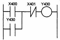
FIG. 23 Latch circuit
4.2 Latching
There are often situations where it is necessary to hold an output energized, even when the input ceases. A simple example of such a situation is a motor which is started by pressing a push button switch.
Though the switch contacts do not remain closed, the motor is required to continue running until a stop push button switch is pressed. The term latch circuit is used for the circuit used to carry out such an operation. It is a self-maintaining circuit in that, after being energized, it maintains that state until another input is received.
An example of a latch circuit is shown in FIG. 23. When the input X400 contacts close, there is an output at Y430. However, when there is an output, another set of contacts || Y430 associated with the output closes. These contacts form an OR logic gate system with the input contacts. Thus, even if the input X400 opens, the circuit will still maintain the output energized. The only way to release the output is by operating the normally closed contact X401.
As an illustration of the application of a latching circuit, consider a motor controlled by stop and start push button switches and for which one signal light must be illuminated when the power is applied to the motor and another when it is not applied. FIG. 24 shows the ladder diagram. When X400 is momentarily closed, Y430 is energized and its contacts close. This results in latching and also the switching off of Y431 and the switching on of Y432. To switch the motor off, X401 is pressed and opens. Y430 contacts open in the top rung and third rung, but close in the second rung. Thus Y431 comes on and Y432 off.
Note that the stop contacts X401 are shown as being programmed as open.
If the stop switch used is normally closed then X401 receives a start-up signal to close. This gives a safer operation than programming X401 as normally closed.
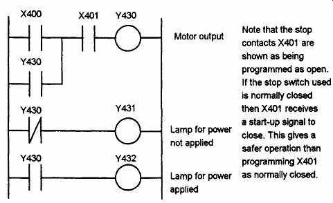
FIG. 24 Motor on-off, with signal lamps, ladder diagram.
Related Articles -- Top of Page -- Home