AMAZON multi-meters discounts AMAZON oscilloscope discounts
<< cont. from part 1
4.3 Internal relays
In PLCs there are elements that behave like relays, being able to be switched on or off and, in turn, switch other devices on or off. Hence the term internal relay. Such internal relays do not exist as real-world switching devices but are merely bits in the storage memory that behave in the same way as relays. For programming, they can be treated in the same way as an external relay output and input. Thus we might have (FIG. 25):
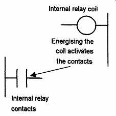
FIG. 25 Internal relay
On one rung of the program:
Inputs to external inputs activate the internal relay output.
On a later rung of the program:
As a consequence of the internal relay output: internal relay contacts are activated and so control some output.
In using an internal relay, it has to be activated on one rung of a program and then its output used to operate switching contacts on another rung, or rungs, of the program. Internal relays can be programmed with as many sets of associated contacts as desired.
To distinguish internal relay outputs from external relay outputs, they are given different types of addresses. Different manufacturers tend to use different terms for internal relays and different ways of expressing their addresses. For example, Mitsubishi uses the term auxiliary relay or marker and the notation M100, M101, etc., the M indicating that it is an internal relay or marker rather than an external device. Siemens use the Xtrm flag and notation F0.0, F0.1, etc. The internal relay switching contacts are designated with the symbol for an input device, namely ||, and given the same address as the internal relay output, e.g. M100. As an illustration of the use that can be made of internal relays, consider the following situation. A system is to be activated when two different sets of input conditions are realised. We might just program this as an AND logic gate system; however, if a number of inputs have to be checked in order that each of the input conditions can be realised, it may be simpler to use an internal relay. The first input conditions then are used to give an output to an internal relay with the associated contacts becoming part of the input conditions with the second input.
FIG. 26 shows a ladder program for such a task. For the first rung: when input X400 or input X402 is closed and input X401 closed, then internal relay M100 is activated. This results in the contacts M100 closing. If input X403 is then activated, there is an output from output Y430. Such a task might be involved in the automatic lifting of a barrier when someone approaches from either side. Input X400 and input X402 are inputs from photoelectric sensors that detect the presence of a person, input X400 being activated from one side of it and input X402 from the other. Input X401 is an enabling switch to enable the system as a whole to be switched on. Thus when input X400 or input X402, and input X401, are activated, there is an output from the internal relay M100. This will close the internal relay contacts M100. If input X403, perhaps a limit switch, detects that the barrier is closed then it is activated and closes. The result is then an output from Y430, a motor which lifts the barrier. If the limit switch detects that the barrier is already open, the person having passed through it, then it remains open and so output Y430 is no longer energized and a counterweight might then close the barrier. The internal relay has enabled two parts of the program to be linked, one part being the detection of the presence of a person and the second part the detection of whether the barrier is already up or down.
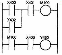
FIG. 26 Program
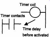
FIG. 27 Timer
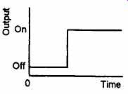
FIG. 28 On-delay timer
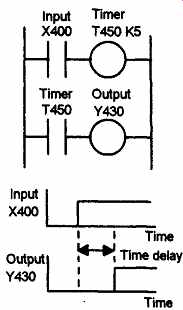
FIG. 29 Ladder program with a delay-on timer
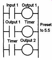
FIG. 30 Sequenced outputs
4.4 Timers
In many control tasks there is a need to control time. For example, a motor or a pump might need to be controlled to operate for a particular interval of time, or perhaps be switched on after some time interval.
PLCs thus have timers as built-in devices. Timers count fractions of seconds or seconds using the internal CPU clock.
PLC manufacturers differ on how timers should be programmed and hence how they can be considered. A common approach is to consider timers to behave like relays with coils which when energized result in the closure or opening of contacts after some pre-set time. The timer is thus treated as an output for a rung with control being exercised over pairs of contacts elsewhere (FIG. 27). There are a number of different forms of timers that can be found with PLCs. With small PLCs there is likely to be just one form, the on-delay timers. These are timers which come on after a particular time delay (FIG. 28). The time duration for which a timer has been set is termed the pre-set and is set in multiples of the time base used. Typical time bases are 10 ms, 100 ms, 1 s, 10 s and 100s.
Thus a pre-set value of 5 with a time base of 100 ms is a time of 500 ms.
FIG. 29 shows a ladder rung diagram involving a delay-on timer.
The timer is like a relay with a coil which is energized when the input X400 occurs (rung 1). It then closes, after some pre-set time delay, its contacts on rung 2. Thus the output from Y430 occurs some pre-set time after the input X400 occurs.
As an illustration of the use of a timer, consider the ladder diagram shown in FIG. 30. When the input 1 is on, the output 1 is switched on. The contacts associated with this output then start the timer. The contacts of the timer will close after the pre-set time delay. In this case with K = 5.5 and using a time base of 1 s the time delay is 5.5 s. When this happens, output 2 is switched on. Thus, following the input 1, output 1 is switched on and followed 5.5 s later by output 2. This illustrates how timed sequence of outputs can be achieved.
FIG. 31 shows how timers can be used to start three outputs, e.g. three motors, in sequence following a single start button being pressed.
When the start push button is pressed there is an output from internal relay IR1. This latches the start input. It also starts both the timers, T1 and T2, and motor 1. When the pre-set time for timer 1 has elapsed then its contacts close and motor 2 starts. When the pre-set time for timer 2 has elapsed then its contacts close and motor 3 starts. The three motors are all stopped by pressing the stop push button. Since this is seen as a complete program, the end instruction has been used.
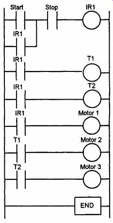
FIG. 31 Motor sequence
4.5 Counters
Counters are provided as built-in elements in PLCs. A counter allows a number of occurrences of input signals to be counted. This might be counting the number of revolutions of a shaft, or perhaps the number of people passing through a door.
A counter is set to some pre-set number value and, when this value of input pulses has been received, it will operate its contacts. Thus normally open contacts would be closed, normally closed contacts opened. There are two types of counter, though PLCs may not include both types. These are down-counters and up-counters. Down-counters count down from the pre-set value to zero, i.e. events are subtracted from the set value. When the counter reaches the zero value, its contacts change state. Most PLCs offer down counting. Up-counters count from zero up to the pre-set value, i.e. events are added until the number reaches the pre-set value.
When the counter reaches the set value, its contacts change state.
Different PLC manufacturers deal with counters in slightly different ways. Some treat the counter as two basic elements: one relay coil to count input pulses and one (RST) to reset the counter, the associated contacts of the counter being used in other rungs. FIG. 32 illustrates this with a basic counting circuit. When there is a pulse input to input 1, the counter is reset. When there is an input to input 2, the counter starts counting, ff the counter is set for, say, 10 pulses, then when 10 pulse inputs have been received at input 2, the counter's contacts will close and there will be an output from output 1. ff at any time during the counting there is an input to input 1, the counter will be reset and start all over again and count for 10 pulses.
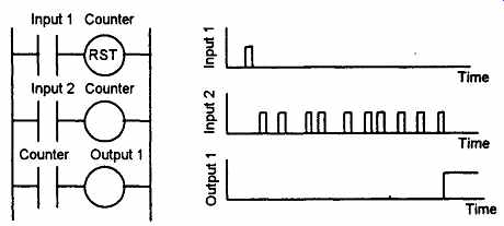
FIG. 32 Basic counter program.
FIG. 33 shows how the above program would appear with a Mitsubishi PLC. The reset and counting elements are combined in a single box spanning the two rungs. You can consider the rectangle to be enclosing the two counter outputs in FIG. 32.
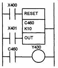
FIG. 33 Mitsubishi program.
Counters can be used to ensure that a particular part of a sequence is repeated a known number of times. This is illustrated by the following program which is designed to enable a three-cylinder, double solenoid-controlled arrangement to give the sequence A+, A-, A+, A~, A+, A-, B^, C+, B-, C-. The A+, A- sequence is repeated three times before B+, C+ , B-, C- occur. We can use a counter to enable this repetition. FIG. 34 shows a possible program. The counter only allows B+ to occur after it has received three inputs corresponding to three a- signals.
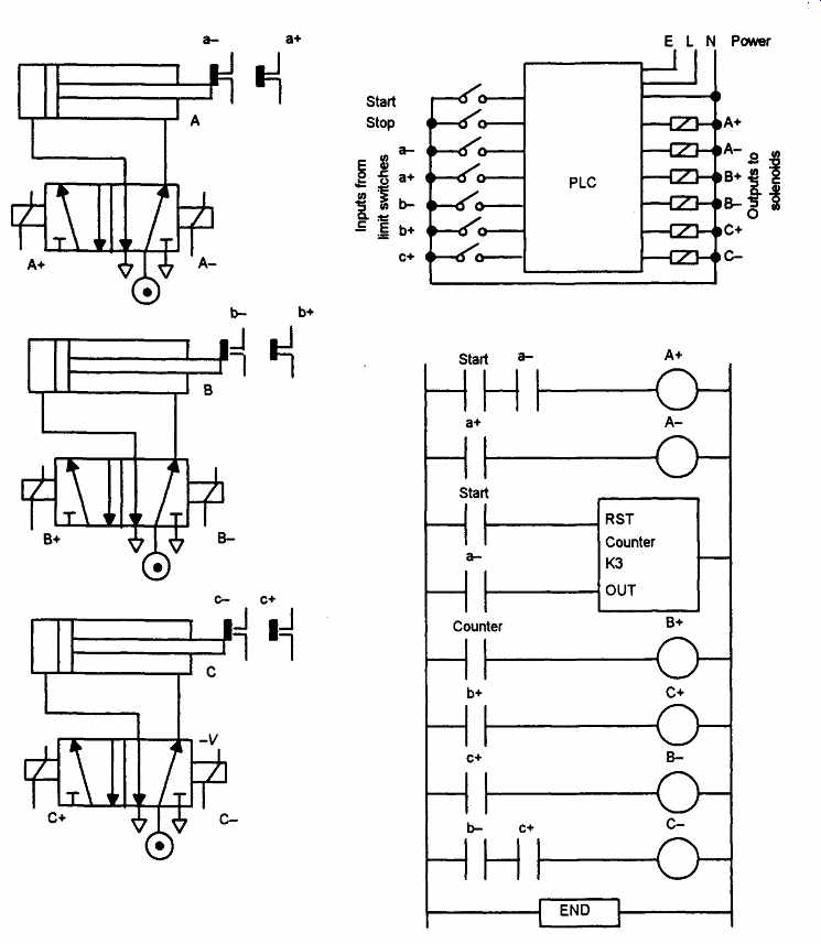
FIG. 34 Three-cylinder system.
5 Case studies
The following case studies are intended to illustrate the application of the PLC programming techniques given in this section.
5.1 Signal lamp to monitor operations
Consider a basic situation where a signal lamp is required to be switched on if a pump is running and the pressure is satisfactory, or if the lamp test switch is closed. For the inputs from the pump and the pressure sensors we have an AND logic situation since both are required if there is to be an output from the lamp. We, however, have an OR logic situation with the test switch in that it is required to give an output of lamp on regardless of whether there is a signal from the AND system.
The ladder program is thus of the form shown in FIG. 35. Note that we tell the PLC when it has reached the end of the program by the use of the END instruction.
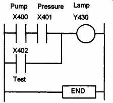
FIG. 35 Signal lamp
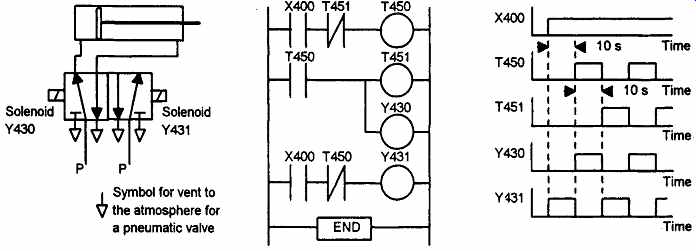
FIG. 36 Cyclic movement of a piston
5.2 Cyclic movement of a piston
Consider the task of obtaining cyclic movement of a piston in a cylinder.
This might be to periodically push workpieces into position in a machine tool with another similar, but out of phase, arrangement being used to remove completed workpieces. FIG. 36 shows the valve and piston arrangement that might be used, a possible ladder program and chart indicating the timing of each output.
Consider both timers set for 10s. When the start contacts X400 are closed, timer T450 starts. Also there is an output from Y431. The output Y431 is one of the solenoids used to actuate the valve. When it is energized it causes the pressure supply P to be applied to the right-hand end of the cylinder and the left-hand side to be connected to the vent to the atmosphere. The piston thus moves to the left. After 10s, the normally open T450 contacts close and the normally closed T450 contacts open. This stops the output Y431, starts the timer T451 and energizes the output Y430. As a result, the pressure supply P is applied to the left-hand side of the piston and the right-hand side connected to the vent to the atmosphere. The piston now moves to the right. After 10 s, the T451 normally closed contacts are opened. This causes the normally closed contacts of T450 to close and so Y431 is energized. Thus the sequence repeats itself.
5.3 Sequential movement of pistons
Consider another task involving three pistons A, B and C that have to be actuated in the sequence: A to the right, A to the left, B to the right, B to the left, C to the right, C to the left (such a sequence is often written A+, A-, B+ , B-, C+, C-). FIG. 37 shows the valves and a ladder program using timers that might be used.
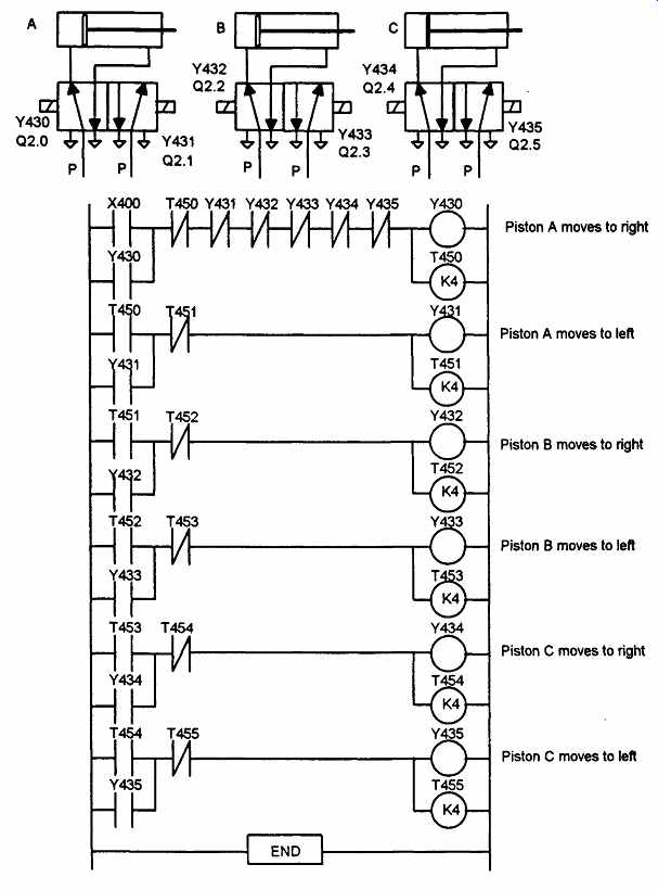
FIG. 37 Sequential movement of pistons
X400 is the start switch. When it is closed there is an output from Y430 and the timer T450 starts. The start switch is latched by the output.
Piston A moves to the right. After the set time, K = 4, the normally closed timer T450 contacts open and the normally open timer T450 contacts close. This switches off Y430 and energizes Y431 and starts timer T451. Piston A moves to the left. In rung 2, the T450 contacts are latched and so the output remains on until the set time has been reached.
When this occurs the normally closed timer T451 contacts open and the normally open T451 contacts close. This switches off Y431 and energizes Y432 and starts timer T452. Piston B moves to the right. Each succeeding rung activates the next solenoid. Thus in sequence, each of the outputs is energized.
5.4 Central heating system
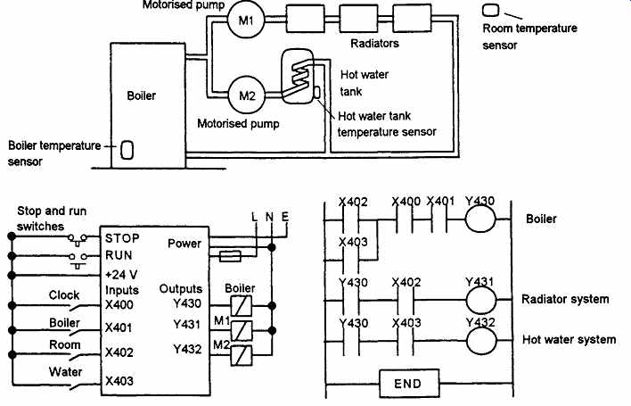
FIG. 38 Central heating system
Consider a domestic central heating system where the central heating boiler is to be thermostatically controlled and supply hot water to the radiator system in the house and also to the hot water tank to provide hot water from the taps in the house. Pump motors have to be switched on to direct the hot water from the boiler to either, or both the radiator and hot water systems according to whether the temperature sensors for the room temperature and the hot water tank indicate that the radiators or tank need heating. The entire system is to be controlled by a clock so that it only operates for certain hours of the day. FIG. 38 shows the system and how a Mitsubishi PLC might be used.
The boiler, output Y430, is switched on if X400 and X401 and either X402 or X403 are switched on. This means if the clock is switched on, the boiler temperature sensor gives an on input, and either the room temperature sensor or the water temperature sensor give on inputs. The motorized valve Ml, output Y431, is switched on if the boiler, Y430, is on and if the room temperature sensor X402 gives an on input. The motorized valve M2, output Y432, is switched on if the boiler, Y430, is on and if the water temperature sensor gives an on input.
Problems
Questions 1 to 6 have four answer options: A, B, C or D. Choose the correct answer from the answer options.
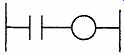
FIG. 39 Problem 1
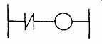
FIG. 40 Problem 2
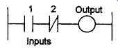
FIG. 41 Problem 3
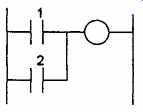
FIG. 42 Problem 4
1. Decide whether each of these statements is True (T) or False (F). FIG. 39 shows a ladder diagram rung for which:
(i) The input contacts are normally open.
(ii) There is an output when there is an input to the contacts.
A (i)T (ii)T
B (i)T (ii)F
C (i)F (ii)T
D (i)F (ii)F
2. Decide whether each of these statements is True (T) or False (F). FIG. 40 shows a ladder diagram rung for which:
(i) The input contacts are normally open.
(ii) There is an output when there is an input to the contacts.
A (i)T (ii)T
B (i)T (ii)F
C (i)F (ii)T
D (i)F (ii)F
3. Decide whether each of these statements is True (T) or False (F). FIG. 41 shows a ladder diagram rung for which:
(i) When only input 1 contacts are activated, there is an output.
(ii) When only input 2 contacts are activated, there is an output.
A (i)T (ii)T
B (i)T (ii)F
C (i)F (ii)T
D (i)F (ii)F
4. Decide whether each of these statements is True (T) or False (F). FIG. 42 shows a ladder diagram rung for which there is an output when:
(i) Inputs 1 and 2 are both activated.
(ii) Either one of inputs 1 and 2 is not activated.
A (i)T (ii)T
B (i)T (ii)F
C (i)F (ii)T
D (i) F (ii) F
5. Decide whether each of these statements is True (T) or False (F). FIG. 43 shows a ladder diagram rung with an output when: (i) Inputs 1 and 2 are both activated, (ii) Input 1 or 2 is activated.
A (i)T (ii)T
B (i)T (ii)F
C (i)F (ii)T
D (i) F (ii) F
6. Decide whether each of these statements is True (T) or False (F). FIG. 44 shows a ladder diagram rung for which there is an output when: (i) Input 1 is momentarily activated before reverting to its normally open state.(ii) Input 2 is activated.
A (i)T (ii)T
B (i)T (ii)F
C (i)F (ii)T
D (i)F (ii)F
Problems 7 to 9 refer to FIG. 45 which shows a ladder diagram with an internal relay, designated IR 1, two inputs Input 1 and Input 2, and an output Output 1.
7. Decide whether each of these statements is True (T) or False (F). For the ladder diagram shown in FIG. 45, there is an output from Output 1 when: (i) There is just an input to Input 1. (ii) There is just an input to Input 2.
A (i)T (ii)T
B (i)T (ii)F
C (i)F (ii)T
D (i)F (ii)F
8. Decide whether each of these statements is True (T) or False (F). For the ladder diagram shown in FIG. 45, there is an output from Output 1 when: (i) There is an input to Input 2 and a momentary input to Input 1. (ii) There is an input to Input 1 or an input to Input 2.
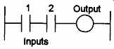
FIG. 43 Problem 5
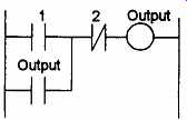
FIG. 44 Problem 6
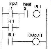
FIG. 45 Problems 7, 8 and 9
A (i)T (ii)T
B (i)T (ii)F
C (i)F (ii)T
D (i)F (ii)F
9. Decide whether each of these statements is True (T) or False (F). For the ladder diagram shown in FIG. 45, the internal relay: (i) Switches on when there is just an input to Input 1. (ii) Switches on when there is an input to Input 1 and to Input 2.
A (i)T (ii)T
B (i)T (ii)F
C (i)F (ii)T
D (i) F (ii) F
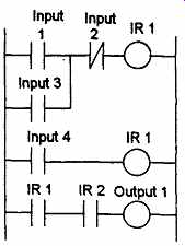
FIG. 46 Problems 10, 11 and 12
Problems 10 to 12 refer to FIG. 46 which shows a ladder diagram involving internal relays IR 1 and IR 2, inputs Input 1, Input 2 and Input 3, and output Output 1.
10. Decide whether each of these statements is True (T) or False (F). For the ladder diagram shown in FIG. 46, the internal relay IR 1 is energized when:
(i) There is an input to Input 1.
(ii) There is an input to Input 3.
A (i)T (ii)T
B (i)T (ii)F
C (i)F (ii)T
D (i)F (ii)F
11. Decide whether each of these statements is True (T) or False (F). For the ladder diagram shown in FIG. 46, the internal relay IR 2 is energized when:
(i) Internal relay IR 1 is energized.
(ii) Input 4 is energized.
A(i)T(ii)T
B (i)T (ii)F
C (i)F (ii)T
D (i)F (ii)F
12. Decide whether each of these statements is True (T) or False (F). For the ladder diagram shown in FIG. 46, there is an output from Output 1 when:
(i) There are inputs to just Input 1, Input 2 and Input 4.
(ii) There are inputs to just Input 3 and Input 4.
A (i)T (ii)T
B (i)T (ii)F
C (i)F (ii)T
D (i) F (ii) F
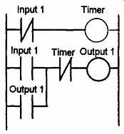
FIG. 47 Problems 13 to 16
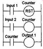
FIG. 48 Problems 16 to 18
Problems 13 to 16 refer to FIG. 47 which shows a ladder diagram with an on-delay timer, an input Input 1 and an output Output 1.
13. Decide whether each of these statements is True (T) or False (F). When there is an input to Input 1 in FIG. 47: (i) The timer starts. (ii) There is an output from Output 1.
A (i)T (ii)T
B (i)T (ii)F
C (i)F (ii)T
D (i) F (ii) F
14. Decide whether each of these statements is True (T) or False (F). The timer in FIG. 47 starts when: (i) There is an output, (ii) The input ceases.
A (i)T (ii)T
B (i)T (ii)F
C (i)F (ii)T
D (i) F (ii) F
15. Decide whether each of these statements is True (T) or False (F). When there is an input to Input 1 in FIG. 47, the output is switched: (i) On for the time for which the timer was pre-set.
(ii) Off for the time for which the timer was pre-set.
A (i)T (ii)T
B (i)T (ii)F
C (i)F (ii)T
D (i) F (ii) F
Problems 16 to 18 refer to FIG. 48 which shows a ladder diagram with a counter, two inputs Input 1 and Input 2 and an output Output 1.
16. Decide whether each of these statements is True (T) or False (F). For the ladder diagram shown in FIG. 48, when the counter is set to 5, there is an output from Output 1 every time: (i) Input 1 has closed 5 times. (ii) Input 2 has closed 5 times.
A (i)T (ii)T
B (i)T (ii)F
C (i)F (ii)T
D (i)F (ii)F
17. Decide whether each of these statements is True (T) or False (F). For the ladder diagram shown in FIG. 48: (i) The first rung gives the condition required to reset the counter, (ii) The second rung gives the condition required to generate pulses to be counted.
A (i)T (ii)T
B (i)T (ii)F
C (i)F (ii)T
D (i)F (ii)F
18. Decide whether each of these statements is True (T) or False (F). When there is an input to Input 1 in FIG. 48: (i) The counter contacts in the third rung close.
(ii) The counter is ready to start counting the pulses from Input 2.
A (i)T (ii)T
B (i)T (ii)F
C (i)F (ii)T
D (i)F (ii)F
19 This problem is essentially concerned with part of the domestic washing machine program. Devise a ladder program to switch on a pump for 100s. It is then to be switched off and a heater switched on for 50s. Then the heater is switched off and another pump is used to empty the water.
20. Devise a ladder program that can be used with a solenoid valve controlled double-acting cylinder, i.e. a cylinder with a piston which can be moved either way by means of solenoids for each of its two positions, and which moves the piston to the right, holds it there for 2 s and then returns it to the left.
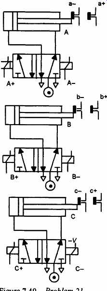
FIG. 49 Problem 21
21. The inputs from the limit switches and the start switch and the outputs to the solenoids of the valves shown in FIG. 49 are connected to a PLC which has the ladder program shown in Fig. 50. What is the sequence of the cylinders?
22. The inputs from the limit switches and the start switch and the outputs to the solenoids of the valves shown in FIG. 51(a) are connected to a PLC which has the ladder program shown in FIG. 51(b). What is the sequence of the cylinders?
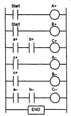
FIG. 50 Problem 21
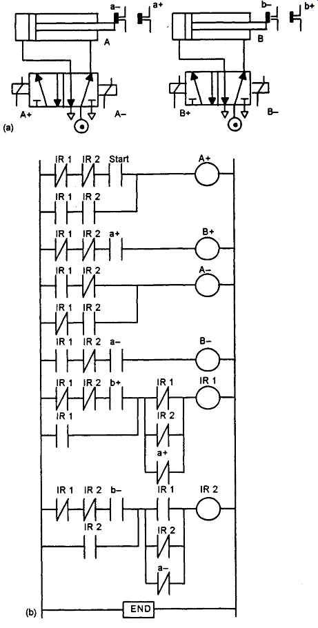
FIG. 51 Problem 22
PREV. | NEXT
Related Articles -- Top of Page -- Home