AMAZON multi-meters discounts AMAZON oscilloscope discounts
Flow sensors are used in many monitoring and control applications, to measure both air and liquid flows. There are many ways of defining flow (mass flow, volume flow, laminar flow, turbulent flow). Usually the amount of a substance flowing (mass flow) is the most important, and if the fluid's density is constant, a volume flow measurement is a useful substitute that is generally easier to perform. There are numerous reliable technologies and sensor types used for this purpose. Some technologies have been applied to both air and liquid flow measurements, as their principles of operation hold true in either application. Other technologies lend themselves to being airflow or liquid flow specific. In this section, we will discuss several of the most commonly used techniques for measuring both airflow and liquid flow. Complementary to flow measurement is level measurement. Used together, flow and level sensors answer the basic question of "how much" in laboratories and industries worldwide. Both measurement processes also share the distinction of being fairly complicated.
1. Methods for Measuring Flow
Flow rate is typically obtained by first measuring the velocity of a fluid in a pipe, duct, or other structure and then multiplying by the known cross-sectional area at the point of measurement. Methods for measuring airflow include thermal anemometers, differential pressure measurement systems, and vortex shedding sensors. Methods used for measuring liquid flow include differential pressure measurement systems, vortex shedding sensors, positive displacement flow sensors, turbine based flow sensors, magnetic flow sensors, and ultrasonic flow sensors.
AMAZON multi-meters discounts AMAZON oscilloscope discounts
Thermal Anemometers
Thermal (or "hot wire") anemometers use the principle that the amount of heat re moved from a heated temperature sensor by a flowing fluid can be related to that fluid's velocity. These sensors typically use a second, unheated temperature sensor to compensate for variations in the air temperature. Hot wire sensors are available as single point instruments for test purposes, or in multi-point arrays for fixed installation. These sensors are better at low airflow measurements than differential pressure types, and are commonly applied to air velocities from 50 to 12,000 feet per minute.
Differential Pressure Measurement
Differential pressure measurement sensor technologies can be used for both airflow and liquid flow measurements. A variety of application-specific sensors used for both airflow and pressure measurements are on the market, as well as differential pressure sensors used for liquid measurements. Differential pressure flowmeters are the most common type of unit in use, particularly for liquid flow measurement.
The operation of differential pressure flowmeters is based on the concept that the pressure drop across the meter is proportional to the square of the flow rate; the flow rate is found by measuring the pressure differential and taking the square root.
Differential pressure flow devices, like most flowmeters, have a primary and secondary element. The primary element causes a change in the kinetic energy, to create the differential pressure in the pipe. The unit must be correctly matched to the pipe size, flow conditions, and the properties of the liquid being measured. In addition, the measurement accuracy of the element must be good over a reasonable range. The secondary element measures the differential pressure and outputs the signal that is converted to the actual flow value.
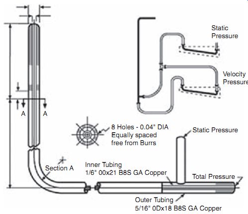
Fig. 1. A Pitot tube.
For airflow measurements, common differential pressure flow devices include Pitot tubes and numerous other types of velocity pressure-sensing tubes, grids, and arrays. All of these sensing elements are combined with a low differential pressure transmitter to produce a signal proportional to the square root of the fluid velocity.
AMAZON multi-meters discounts AMAZON oscilloscope discounts
A Pitot tube consists of two tubes that measure pressure at different locations within a pipe. One tube measures static pressure, usually at the pipe wall, and the other measures impact pressure (static pressure plus velocity head). The faster the flow rate, the larger the impact pressure. Pitot tubes use the difference between impact and static pressure to calculate flow rate. Pitot tubes are low-cost devices, but they have the drawback that they only measure flow at a single point and need to be installed at the point of maximum flow. Changes in velocity profile can cause major errors. They are also prone to clogging. Averaging Pitot tubes have several ports for measuring flow at multiple locations; this makes it possible to take changing velocity profiles into account.
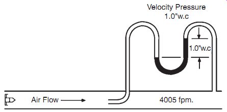
ill.2: Velocity pressure measurement using U tube manometer.
ill.2 shows an example of a velocity pressure measurement with a U tube manometer. Air Flow 4005 fpm.
Some differential pressure-based flow measurement systems include transmitters with the ability to extract the square root of the measured pressure electronically and provide a signal that is linear with respect to velocity. Others provide a signal proportional to measured pressure and depend on the control system to calculate the square root. Once the velocity is obtained, flow can then be found by multiplying by the cross-sectional area of the duct. Velocity range is limited by the range and resolution of the pressure transmitter used. Most differential pressure units are limited to a minimum velocity in the range of 400 to 600 feet per minute. Maximum velocity is limited only by the sensor's durability.
To measure water flow, differential pressure flow devices typically either measure velocity pressure (insertion tube type), or measure the drop in pressure across a known restriction. Orifice plates, flow nozzles, Venturis, and Pitot tubes are types of restrictions commonly used.
Insertion tube flow sensors are typically made of a tube with multiple openings across the width of the flow stream, to give an average of the velocity differential across the tube and an internal baffle between upstream and downstream openings to obtain a differential pressure. Insertion tube meters have a low permanent pressure loss and can be satisfactory for many common applications.
A concentric orifice plate is the simplest and least costly of the differential pressure de vices. The orifice plate constricts the flow of a fluid and produces a differential pressure across the plate (see). This results in a high pressure upstream and a low pressure downstream that is proportional to the square of the flow velocity. An orifice plate usually produces a greater overall pressure loss than other flow elements. One advantage of this device is that cost does not increase significantly with pipe size.
Venturi tubes are the largest and most expensive differential pressure device. They work by gradually narrowing the diameter of the pipe, and measuring the pressure drop that results. An expanding section of the differential pressure device then returns the flow to close to its original pressure. As with the orifice plate, the differential pressure measurement is converted into a corresponding flow rate. Venturi tubes can typically be used only in those applications requiring a low pressure drop and a high accuracy reading. They are often used in large diameter pipes.
Flow nozzles are actually a variation on the Venturi tube, with the nozzle opening being an elliptical restriction in the flow, but having no outlet area for the pressure recovery. Pressure taps are located approximately 1/2 pipe diameter down stream and 1 pipe diameter upstream.
The flow nozzle is a high-velocity flow meter used where turbulence is high (Reynolds numbers above 50,000), as in steam flow applications. The pres sure drop of a flow nozzle is between that of a Venturi tube and the orifice plate (30 to 95 percent).
Benefits of differential pressure instruments include their low cost, simplicity of operation and installation, and proven performance. It’s a well-understood technology. Disadvantages of these devices can include permanent pressure loss; dirt buildup and clogging; large size and bulkiness of some devices; and unsuitability for use with certain types of fluids.
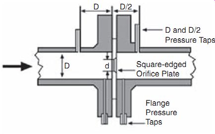
ill. 3: The concentric orifice. Square-edged Orifice Plate; Flange Pressure
Taps
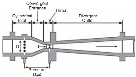
ill.4: The Venturi tube. Divergent Outlet Throat Convergent Entrance Cylindrical
Inlet
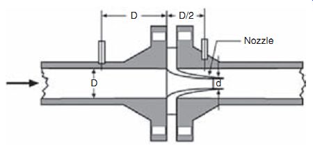
ill.5: The flow nozzle.
Vortex-Shedding Sensors
These flow sensors use the principle (Von Karman) that when a fluid flows around an obstruction in the flow stream (bluff object), eddies or vortices are shed alternately downstream of the object. The frequency of the vortex shedding is proportional to the velocity of the flowing fluid. Single sensors are used in small ducts, and arrays of sensors are applied to larger ducts, as with the other types of airflow measuring instruments. Vortex shedding airflow sensors are commonly used with air velocities in the range of 350 to 6000 feet per minute. These meters are equally suitable for flow rate or flow total measurements. Use with slurries or high viscosity fluids is not recommended.
Positive Displacement Flow Sensors
These flow measurement devices are used where high accuracy at high turndown (ratio of the full range of the device to the minimum measurable flow) is necessary and some permanent pressure loss won’t cause excessive energy consumption. These units operate by separating liquids into measured segments, and then moving them on. Each segment is then counted by a connecting register. They are useful for viscous liquid flows or where a single mechanical meter is needed. Common types of positive displacement flow meters include lobed and gear type meters, nutating disk meters, rotary-vane meters, and oscillating piston meters. These meters are typically made of metals such as brass, bronze, and cast iron, but can also be constructed of engineered plastic, depending on the application.
Because of the close tolerances needed between moving parts of positive displacement flow meters, they can be prone to mechanical problems resulting from suspended solids in the flow stream. Positive displacement meters are available with flow indicators and totalizers that can be read manually. These devices are relatively costly.
Turbine-Based Flow Sensors
Turbine and propeller type meters use the principle that liquid flowing through the turbine or propeller will cause the rotor to spin at a speed directly related to flow rate.
Electrical pulses can be counted and totaled. These devices are available in full bore, line-mounted versions and insertion types where only a part of the flow being measured passes over the rotating element. Turbine flow meters, when properly specified and installed, offer good accuracy, especially with low viscosity fluids. Insertion types are used for less critical applications; however, they are often easier to maintain and inspect because they can be removed without disturbing the main piping.
Mass Flowmeters
Mass-related processes such as chemical reactions, heat transfer, etc. require more accurate flow measurements, and this has led to the development of mass flow meters.
A number of designs are available, but the most common is the Coriolis meter, the operation of which is based on the phenomenon called the Coriolis force. Coriolis meters are true mass meters that measure the mass rate of flow directly, as opposed to measuring volume flow. Since mass does not change, the meter is linear without having to be adjusted for variations in liquid properties. Also, there is no need to compensate for changing temperatures and pressure conditions. This type of flowmeter is particularly useful for measuring liquids with a viscosity that varies with velocity at given temperatures and pressures.
Coriolis meters are available in various designs. One popular device consists of a U shaped flow tube enclosed in a sensor housing connected to an electronics unit. The sensing unit can be installed directly into any process, and the electronics unit can be located up to 500 feet from the sensor. Inside the sensor housing, the U-shaped flow tube is vibrated at its natural frequency by a magnetic device located at the bend of the tube. This is similar to the vibration of a tuning fork, covering less than 0.1 in. and completing a full cycle about 80 times/sec. As the liquid flows through the tube, it’s forced to take on the vertical movement of the tube. This causes the liquid to exert a force on the tube, causing the tube to twist. The amount of twist is directly proportional to the mass flow rate of the liquid flowing through the tube. Magnetic sensors located on each side of the flow tube measure the tube velocities, which change as the tube twists. The sensors feed this information to the electronics unit, where it’s processed and converted to a voltage proportional to mass flow rate. This flowmeter has a wide range of applications, from adhesives and coatings to liquid nitrogen.
Electromagnetic Flow Sensors
Operation of these sensors is based upon Faraday's Law of electromagnetic induction, which says that a voltage will be induced when a conductor moves through a magnetic field.
The liquid is the conductor, and the magnetic field is created by energized coils out side the flow tube. The voltage produced is proportional to the flow rate. Electrodes mounted in the pipe wall sense the induced voltage, which is measured by the secondary element.
Electromagnetic flow meters are applied in measuring the flow rate of conducting liquids (including water) where a high quality, low maintenance system is needed. The cost of magnetic flow meters is high relative to other types of flowmeters. They do have many advantages, including: they can measure difficult and corrosive liquids and slurries, and they can mea sure reverse flow.
Ultrasonic Flow Sensors
Ultrasonic flow sensors can be divided into Doppler sensors and transit, or time-of-travel, sensors. Doppler sensors measure the frequency shifts caused by liquid flow. Two transducers are mounted in a case attached to one side of the pipe; a signal of a known frequency is delivered to the liquid to be measured.
Bubbles, solids or any other discontinuity in the liquid cause the pulse to be reflected to the receiver element. Because the liquid that causes the refection is moving, the frequency of the returned pulse shifts, and the frequency shift is proportional to the velocity of the liquid.
With transit, or time-of-travel, meters, transducers are mounted on each side of the pipe, such that the sound waves traveling between the devices are at a 45-degree angle to the direction of liquid flow. The speed of the signal moving between the transducers increases or decreases with the direction of transmission and the velocity of the liquid being measured. A time-differential relationship proportional to the flow can be obtained by transmitting the signal alternately in both directions. One limitation of this type of sensor is that the liquids that are being measured have to be relatively free of solids or entrained gases in order to minimize signal scattering and absorption.
Advantages of ultrasonic flow meters are that they are non-intrusive and their cost is moderate. Many models are designed to clamp onto existing pipe.
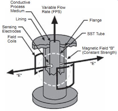
ill.6: The magnetic head flow meter. Magnetic Field "B" (Constant
Strength) SST Tube Flange Variable Flow Rate (FPS) Field Coils Sensing Electrodes
Lining Conductive Process Medium
Laser Doppler Flow Measurement
The laser doppler anemometer (LDA) is a well-established technique that has been widely used for fluid dynamic measurements in liquids and gases for well over 30 years. The directional sensitivity and non-intrusiveness of LDA make it useful for applications with reversing flow, chemically reacting or high-temperature media, and rotating machinery, where physical sensors might be difficult or impossible to use. This technique does, however, require tracer particles in the flow.
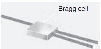
ill.8 Bragg cell used as a beam splitter. Bragg cell
A Bragg cell is often used as the beam splitter. It’s a glass crystal with a vibrating piezo crystal attached. The vibration generates acoustical waves which act like an optical grid.
Two beams of equal intensity exit the Bragg cell, with frequencies f_0 and f_shift, and these are focused into optical fibers that bring them to a probe. In the probe, the parallel exit beams from the fibers are focused by a lens to intersect in a region called the measurement volume, which is typically a few millimeters long and is where the measurement is made.
The light intensity is modulated due to interference between the laser beams which produces parallel planes of high light intensity, called fringes. The fringe distance d_f is defined by the wavelength of the laser light and the angle between the beams:
d_f = λ/2 sin (theta/2)Flow velocity information comes from light scattered by tiny "seeding" particles carried in the fluid as they move through the measurement volume. The scattered light contains a Doppler shift--the Doppler frequency fD--which is proportional to the velocity component perpendicular to the bisector of the two laser beams, which corresponds to the x axis of the measurement volume.
A receiver lens collects the scattered light and focuses it on a photo-detector. An interference filter mounted in front of the photo-detector passes only the required wavelength, removing noise from ambient light and from other wavelengths. The photo-detector converts the fluctuating light intensity into an electrical signal, the Doppler burst. The Doppler bursts are filtered and amplified in the signal processor, which determines fD for each particle, often by frequency analysis using the fast Fourier transform (FFT) algorithm.
The fringe spacing df provides information about the distance traveled by the particle.
The Doppler frequency fD provides information about the time: t = 1/fD . Since velocity equals distance divided by time, the expression for velocity thus becomes:
V = d_f * fD
With regard to the particle seeding, it’s often the case that liquids contain adequate natural seeding, but typically gases must be seeded. Ideally, the particles should be small enough to follow the flow, but large enough to scatter enough light to obtain a good signal-to-noise ratio at the photo-detector output. The size range of particles is usually between 1 µm and 10 µm. The particle material can be solid (powder) or liquid (droplets).
2. Selecting Flow Sensors
Improper device selection accounts for 90 percent of the problems encountered with flowmeters. The most important requirement in selecting a sensor is understanding exactly what the device is supposed to do. Here are important questions to ask during the selection process:
++ Is the measurement for a process control application, where repeatability is the major concern, or for accounting or custody transfer, where high accuracy is important?
++ Is local indication or a remote signal required? If a remote output is required, is it to be a proportional signal, or a contact closure to start or stop another device?
++ Is the liquid to be measured clean, viscous, or a slurry?
++ Is the liquid to be measured electrically conductive?
++ What is the specific gravity or density of the liquid to be measured?
++ What flow rates are involved in the application?
++ What are the process's operating temperatures and pressures?
++ What accuracy, range, linearity, repeatability, and piping requirements must be considered?
It’s also important to know what a flowmeter cannot do before a final selection is made. Each type of sensor has advantages and disadvantages, and the degree of performance satisfaction is directly related to how well an instrument's capabilities and shortcomings are matched to the application's requirements. Most sensor suppliers are eager to help their customers select the appropriate flowmeter for a particular application. Many provide questionnaires, checklists, and specification sheets designed to obtain the critical information necessary to match the correct flowmeter to the job.
Technological advances must also be taken into consideration. One common mistake is to select a design that was popular for a given application years ago, assuming that it’s still the best choice. Many changes and innovations may have occurred in recent years in flowmeter technology for that particular application, making the choice much broader.
3. Installation and Maintenance
Airflow sensors operate most efficiently in sections of pipes or ducts that have uniform, fully developed flow. In order for measurements to be reliable, all airflow sensing devices should be installed in accordance with the manufacturer's recommended straight runs of upstream and downstream duct. Some manufacturers offer flow-straightening elements that can be installed upstream of the sensing array to improve undesirable flow conditions. These should be considered when conditions don’t permit installation with the required straight runs of duct upstream and down stream from the sensor.
All liquid flow sensors also operate best when measuring fully developed, uniform flow. Sensors should be installed in accordance with the manufacturer's recommended straight runs of upstream and downstream pipe in order to obtain the most reliable measurements.
Although most suppliers offer flowmeter installation service, a high percentage of users choose to install their own equipment. This can lead to installation errors, such as not allowing enough upstream and downstream straight-run piping, as described above. Every sensor design has a certain amount of tolerance for unstable velocity conditions in the pipe, but all devices require proper piping configurations to operate efficiently, so that a normal flow pattern for the device is provided. Without it, accuracy and performance are adversely affected. Flowmeters are also occasionally installed backwards (especially with orifice plates). Pressure-sensing lines may also be reversed.
With electrical components, intrinsic safety is an important consideration in hazardous areas. Stray magnetic fields are found in most industrial plants. Power lines, relays, solenoids, transformers, motors, and generators all contribute electromagnetic interference, and users must ensure that the flowmeter they have selected is immune to such interference. Most problems occur with the electronic components in secondary elements, which must be protected. Strict adherence to the manufacturer's recommended installation practices will usually prevent such problems.
Calibration
An initial calibration is required with all flowmeters; usually the calibration is handled by the manufacturer. However, if qualified personnel are available, this can be handled by the sensor purchaser. The necessity of recalibration depends a great deal on how well the device suits the application. Some liquids that pass through flow meters are abrasive, erosive, or corrosive, and in time, portions of the device will deteriorate enough to affect its performance. Some designs are more susceptible to damage than others. E.g., wear of individual turbine blades can cause performance changes. If the application is critical, flowmeter accuracy should be checked often. In other cases, recalibration may not be necessary because the application is noncritical or because nothing in the environment affects the meter's performance.
Some flowmeters require special equipment for calibration. Most manufacturers will provide this service in their own facility or in the user's facility, where they will bring the equipment for on-site calibration.
Maintenance
Flowmeters that have no moving parts usually need less attention than units with moving parts, but all flowmeters eventually require some type of maintenance.
With differential pressure flowmeters, primary elements require extensive valves, pipes, and fittings when they are connected to their secondary elements, so maintenance can be a recurring effort. Impulse lines can plug or corrode and have to be cleaned or replaced. Flowmeters with moving parts require periodic internal inspection, especially if the liquid being metered is dirty or viscous. Installing filters ahead of such units can help to minimize fouling and wear. Ultrasonic or electromagnetic flowmeters can develop problems with their secondary element's electronic components. Pressure sensors associated with secondary elements should be periodically removed and inspected.
Applications where coating can occur also represent potential problems for devices such as magnetic or ultrasonic units. If the coating is insulating, the operation of magnetic flowmeters will ultimately be impaired if the electrodes are insulated from the liquid. Periodic cleaning helps to prevent this. With ultrasonic flowmeters, refraction angles may change and the sonic energy absorbed by the coating will cause the meter to become inoperative.
4. Recent Advances in Flow Sensors
A recent study conducted showed that a major shift is taking place in the field of flow measurement, to "new technology" flowmeters. "New technology" flowmeters are defined in the study as magnetic, ultra sonic, Coriolis, vortex, and multivariable differential pressure meters. These have four features in common:
1. They were introduced in the last 50 years.
2. They make use of technological advances that solve some of the problems inherent in older types of flow measurement devices.
3. They are the predominant focus of new product development by manufacturers.
4. Their performance, including accuracy, is better than that of "traditional" flowmeter technology.
More features are typically provided with these types of flowmeters. This includes software capabilities, more application-specific packages, and extremely durable construction methods. Self-diagnostics is one such feature that users are looking for in flowmeters.
Recent innovations have taken place with differential pressure flowmeters, including the development of very high accuracy differential transmitters, the use of multivariable transmitters, and differential pressure transmitters that contain an integrated primary element. A very significant development has been the emergence of the integrated differential flowmeter. In the past, users purchased primary elements from one company and transmitters from another. Now transmitters are offered with an integrated primary element. The recent trend has been toward smarter and more accurate transmitters. However, it's important to understand that the transmitter is only one element in the system, and other variables contribute to flow accuracy.
With ultrasonic flowmeters, a new class of accurate and low-cost devices for small-diameter pipes (1/4 inch to 2 inches in diameter) is emerging, based on micro-electromechanical systems (MEMS) ultrasonic sensors and a mixed-signal, application-specific integrated circuit (ASIC) control chip. This technique offers an alternative to traditional mechanical meters or more expensive vortex or mass flow meters for selected applications in smaller diameter pipes. The electronic output can be fed directly into process control and monitoring equipment. Also, the device can perform self-testing. It’s very well-suited for measuring clean gas flow.
5. Level Sensors
Types of Liquid Level Sensors
As previously stated, level sensing is closely related to flow sensing. The most common application for level sensing is tank measurement and control operations. A number of level sensing technologies are currently available, including hydrostatic pressure, ultrasonic, RF capacitance, magnetorestrictive-based, and radar measurement systems.
Hydrostatic
Level measurement using differential hydrostatic pressure is based on the principle that the hydrostatic pressure difference between the top and bottom of a column of liquid is related to the density of the liquid and the height of the column. Pressure transmitters are available that are con figured for level monitoring applications. Pres sure instruments can also be remotely located. However, this requires field calibration of the transmitter to compensate for elevation difference between the sensor and the level being measured.
Bubbler type hydrostatic level instruments have been developed for use with atmospheric pressure underground tanks, sewage sumps and tanks, and other applications that cannot have a transmitter mounted below the level being sensed, or that are prone to plugging. Bubbler systems bleed a small amount of compressed air (or other gas) through a tube immersed in the liquid, with an outlet at or below the lowest monitored liquid level. The flow rate of the air is regulated so that the pressure loss of the air in the tube is negligible and the resulting pressure at any point in the tube is approximately equal to the hydrostatic head of the liquid in the tank.
The accuracy of hydrostatic level instruments is related to the accuracy of the pressure sensor used.
Smart differential-pressure (DP) transmitters can be adapted for level measurements and are being used extensively in industry, producing a renewed popularity of this sensor technology. Smart transmitters and 4-20 mA signals are used to communicate to/from remote distributed control systems (DCSs), programmable logic controllers (PLCs), and other control systems. Hydrostatic tank gauging (HTG) is an emerging application using this technique for accurately measuring liquid inventory and to monitor tank transfers. The level measurements can be digitally networked for remote computer access.
Ultrasonic
Ultrasonic level sensors emit sound waves, and the liquid surface reflects the sound waves back to the source. The transit time is proportional to the distance between the liquid surface and the transmitter. These sensors are ideal for noncontact level sensing of very viscous fluids such as heavy oil, latex, and slurries. Practically, there are limitations to this method, which include:
++ foam on the surface can absorb sound
++ speed of sound varies with temperature
++ turbulence can cause inaccurate readings.
RF Capacitance
Capacitance level transmitters work on the principle that a capacitive circuit can be formed between a probe and a vessel wall. The capacitance changes with a change in fluid level, because all common liquids have a dielectric constant higher than that of air. The probe connects to an RF transmitter mounted externally on the tank.
Transmission of the level measurement can be in various forms, and the receiving instrument could be a PC, a chart recorder, a distributed control system (DCS), a programmable logic controller (PLC), etc. These sensors are useful in sensing the levels of a variety of aqueous and organic liquids and slurries, and liquid chemicals such as quicklime. There are also dual probe capacitance level sensors that can be used to sense the interface between two liquids that have very different dielectric constants.
These sensors are rugged, easy to use, contain no moving parts, and are simple to clean. They can be designed for very high temperature and pressure applications.
There are variations of the basic RF systems called RF Impedance and RF Admittance. (Impedance is the total opposition to current flow in an AC or RF circuit; admittance is the reciprocal of impedance and measures how readily current flows in a circuit.) These techniques offer some improvements over the basic RF capacitance method, including better reliability and a larger range of applications.
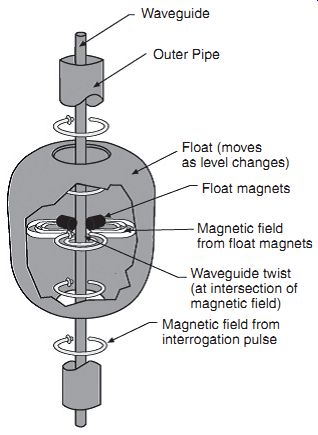
ill. 5-1: Magnetostrictive level
sensors. Magnetic field from interrogation pulse; Waveguide twist (at intersection
of magnetic field); Magnetic field from float magnets; Float magnets; Float
(moves as level changes); Waveguide; Outer Pipe
Magnetostrictive
Magnetostrictive level transmitters are based on the principle that an external magnetic field can be used to cause the refection of an electromagnetic wave in a waveguide constructed of magnetostrictive material. The probe is composed of three concentric members. The outermost member is a protective outer pipe. Inside the outer pipe is a waveguide, which is a formed element constructed of a magnetostrictive material. A low-current interrogation pulse is generated in the transmitter electronics and transmitted down the waveguide, which creates an electro magnetic field along the length of the waveguide. When this magnetic field interacts with the permanent magnetic field of a magnet mounted inside the float, a torsional strain pulse, or waveguide twist results. This waveguide twist is detected as a return pulse. The time between the initiation of the interrogation pulse and the detection of the return pulse is used to determine the level measurement with a high degree of accuracy and reliability.
In the past ten years, microwave or radar technology for level measurement has become more commonly used. This is a rapidly changing area. Formerly this technology was only used in high-accuracy applications, but the development of new techniques and mass production has led to radar becoming more affordable for more varied applications.
Microwave Radar Level Sensing
All of the types of radar level measurement use the basic principles of firing micro waves downward from a sensor located on top of the tank or other vessel; part of the energy is reflected back to the sensor from the surface of the substance being measured. The time of flight of the signal is used to measure the level.
Radar level gauging can be divided into two broad areas: through-air radar and guided wave radar (GWR), also called micropower impulse radar (MIR). Through-air radar can be further broken down into two categories: pulsed wave time of flight and frequency-modulated continuous wave (FMCW). Although both use microwave signals fired into the vapor space above the substance being measured, the return signal processing, manipulation and resultant distance calculation are different.
GWR
Unlike through-air radar systems, GWR is an invasive technology. It appears similar to RF Admittance sensor technology, but it does not have the same capabilities of coping with extremes of pressure, temperature or product coating. Pulses of electro magnetic energy are emitted from the base of the transmitter down the waveguide (a cable or rod). When the signal reaches a point where a change in dielectric constant occurs, usually at the surface of the substance, some of this signal is reflected back.
The amount of signal refection is therefore proportional to the difference in dielectric constant between the waveguide and the substance. In short, substances having a higher dielectric / conductivity provide stronger return signals.
The level measurement itself is a function of the time from when the electromagnetic signal is emitted to the time at which the resultant receive echo is received. This radar technology is often referred to as time domain reflectometry (TDR) radar. The propagation of the signal along a waveguide does eliminate false echoes and helps to minimize signal loss due to dust or vapors. Also, operation is possible in applications with changing vapor space humidity or fluctuating product dielectric constant. It should, however, be noted that, like all radar gauge types, low dielectric materials can cause problems. In addition, the guide can be damaged or corroded.
Systems are available with both single and dual waveguides, depending on the application. Dual waveguide systems tend to provide somewhat greater flexibility and are suitable for interface measurements, materials with a low dielectric, or where foam is present. The position of a liquid interface is measured by using that part of the initial electromagnetic pulse which is not reflected by the surface of the upper phase. This energy continues down the waveguide until it meets the liquid / liquid interface and a percentage of it’s reflected back toward the gauge. The dielectric constant of the upper phase has to be known in order for an accurate measurement to be taken, since the gauge electronics must compensate for the resulting change in speed of the electromagnetic pulse through the upper phase, since it will be different from that of its speed through the air space.
Through-air Radar
Pulsed radar, or pulsed time-of-flight, is similar to the ultrasonic method of level measurement. A radar pulse is aimed at the surface of the substance being measured and the time for the pulse to return is used to find the level. This method uses lower power than FMCW and its performance can be affected by foam, obstructions in the vessel, and low-dielectric materials.
FMCW systems are non-invasive and continuously emit a swept frequency signal.
In this type of radar technology, distance is inferred from the difference in frequency between the transmit and receive signals at any point in time. Although this technique provides an inferential measurement, it can be extremely accurate. The level of signal processing associated with FMCW radar gauges and the resulting power requirements means that two-wire gages of this type are suitable only for the simpler applications, with most applications requiring four-wire devices.
Selecting an appropriate antenna type and size is a crucial factor for achieving a focused beam and adequate return echo. Both cone and parabolic dish antennas are used for the through-air techniques. Cone antennas tend to keep the signals in a narrower, downward path while the dish antennas tend to produce a wider signal path. Factors such as foam in the tank, obstructions, and turbulence can affect antenna type and size choices.
Selecting a Level Sensing Technology
When choosing a method for any particular application, many factors beyond initial costs must be taken into consideration. The most important factors that sensor manufacturers need to know about a level measurement application are:
++ name and characteristics of the material to be measured, whether solid, liquid, slurry, powder, or granular. The dielectric constant K is of particular importance, as well as viscosity, density, conductivity, and consistency (oily, watery, etc.).
++ process information, such as pressure and temperature, degree of turbulence, and tank or vessel material.
++ power requirements.
++ main use of the vessel containing the material to be measured (storage, water separation, sump, etc.), and its size and shape, and location of any obstructions.
6. Applicable Standards
NIST Fluid Flow Group
Establishes, maintains, and disseminates standards for U.S. industry for fluid flowrate and fluid quantity measurements.
International Electrotechnical Commission
Establishes international standards for process control and flowmeters.
API Manual for Petroleum Measurement, Section 3.1A, "Manual Gauging of Petroleum and Petroleum Products." A commonly referenced U.S. standard for the manual level gauging of stationary tanks.
OIML R 85 (E)
A widely recognized international standard for custody transfer from the Organization Internationale Metrologie Legale, specifying level measurement instrument performance.
NEXT: Force, Load and Weight Sensors
PREV: