AMAZON multi-meters discounts AMAZON oscilloscope discounts
1. Introduction
Measurement of a force, load, or a weight can be accomplished by a multitude of different sensors. While other technologies exist, the most commonly used sensors are generally based on either piezoelectric quartz crystal or strain gage sensing elements, which will be the focus of this section.
Before proceeding, it’s important to recognize the difference between force, load, and weight, as these terms are often incorrectly used interchangeably with one another.
Force: The measurement of the interaction between bodies. Load: The measurement of the force exerted on a body. Weight: The measurement of gravitational forces acting on a body.
2. Quartz Sensors
Technology Fundamentals
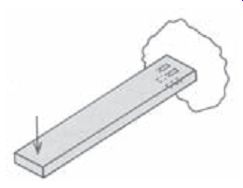
Quartz force sensors are ideally designed and suited for the measurement of dynamic oscillating forces, impact, or high speed compression/tension forces. The basic de sign utilizes the piezoelectric principle, where applied mechanical stresses are converted into an electrostatic charge that accumulates on the surface of the crystal. See ill.
The quartz crystals of a piezoelectric force sensor generate an electrostatic charge only when force is applied to or removed from them. In other words, if you apply a static force to a piezoelectric force sensor, the electrostatic charge output initially generated will eventually leak away and the sensor output ultimately will return to zero.
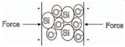
ill.1: Piezoelectric effect.
The rate at which the charge leaks back to zero is exponential and based on the sensor's discharge time constant (DTC). DTC is defined as the time required for a sensor or measuring system to discharge its signal to 37% of the original value from a step change of measurand. This value (seconds) is generally known and is determined by multiplying the lowest insulation resistance path (ohms) by the total capacitance (farads) of the system prior to the amplifier circuit. (This is true of any piezoelectric sensor, whether the operation is force, pressure or vibration monitoring.) The DTC of a system directly relates to the low frequency monitoring capabilities of a system. It’s because of this characteristic that piezoelectric force sensors can only be used for "quasi-static" measurements and are not generally used for weighing applications.
To help clarify the DTC characteristic, assume a weight is placed on top of a piezoelectric force sensor. Initially, the piezoelectric sensing crystals will generate a charge (Q), which is immediately seen at the input to the built-in (or external) amplifier.
AMAZON multi-meters discounts AMAZON oscilloscope discounts
However, after this initial step input, the charge signal decays according to the equation:
q = Qe-t/RC
where:
q = instantaneous charge (Coulomb)
Q = initial quantity of charge (Coulomb)
R = resistance prior to amplifier (ohm)
C = total capacitance prior to amplifier (Farad)
e = base of natural log (2.718)
t = time elapsed after time zero (Second)
This equation is graphically represented. Decay due to discharge time constant (DTC).
The product of R and C represents the DTC (in seconds) of the sensor. It can be inferred that the longer the DTC, the more accurately the sensor will be able to track longer duration events. Generally, piezoelectric force sensors with built-in electronics can have time constants that vary from just a few seconds to >2000 seconds. Special time constants can be supplied by altering the resistor value, R, in the sensor's built-in circuitry. Charge mode sensors, which don’t contain built-in circuitry. require an external amplifier ("charge amplifier") to set the DTC. Some charge amplifiers provide an adjustable DTC.
It should also be mentioned how the range of the force sensor is determined. For sensors that contain built-in circuitry, the range is set by the manufacturer and can be determined by examining the performance specifications for the sensor. For sensors which don’t contain built-in circuitry, the range is set by the external amplifier. There are a number of trade-offs between each type. See Reference 2 for additional information.
AMAZON multi-meters discounts AMAZON oscilloscope discounts
Sensor Types
Charge Mode, High-Impedance, Piezoelectric Force Sensor
A charge mode piezoelectric force sensor, when stressed, generates an electrostatic charge from the crystals. For accurate analysis or recording purposes, this high impedance charge must be routed through low noise cable to an impedance converting amplifier, such as a laboratory charge amplifier or source follower. (Connection of the sensor directly to a readout device such as an oscilloscope may be possible for high frequency impact indication, but is not suitable for most quantitative force measurements.) The primary function of the external amplifier is to convert the high impedance charge output to a usable low impedance voltage signal for analysis or recording purposes. ill.3 shows a typical charge mode sensor system schematic including: sensor, low noise cable, and charge amplifier.
As previously mentioned, in a charge mode system, the sensors don’t contain built-in amplifiers. There fore, the sensor range and DTC are determined by the settings on an external charge amplifier.
A feedback resistor working together with a capacitor on the operational amplifier determines these characteristics. Laboratory-style charge amplifiers generally feature a variety of ranging options as well as short, medium and long time constant selections.
(It’s assumed that the electrical insulation resistance of the force sensor and cable connecting to the charge amplifier are larger than that of the feedback resistor in the charge amplifier; otherwise, performance degradation issues, such as signal drift, may arise. Therefore, to assure this, the force sensor connection point and cable must be kept clean and dry.)
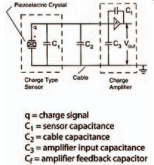
ill.3: Charge mode sensor system.
ill.4: Voltage mode sensor system.
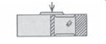
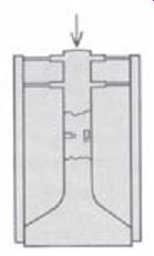
ill.5: Cross section of a general purpose force sensor.
Voltage Mode, Low-Impedance, Piezoelectric Force Sensor
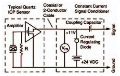
Voltage mode or low impedance force sensors share the same basic design used in charge mode force sensors, but incorporate a built-in microelectronic amplifier. This amplifier serves to convert the high impedance charge output from the quartz crystals into a low impedance voltage signal for analysis or recording. This type of sensor, powered by separate constant current source, operates over long ordinary coaxial or ribbon cables without signal degradation. Additionally, the low impedance voltage signal is not affected by triboelectric cable noise (noise caused by vibration or movement of the cable) or environmental contaminants.
ill.4 shows a complete voltage mode sensor system schematic.
The sensor range and DTC are fixed by the components in the voltage mode sensor's internal amplifier. (It’s assumed that the DTC of the signal conditioner is greater than that of the force sensor.)
Piezoelectric Force Sensor Construction
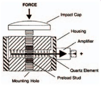
The basic mechanical construction of general purpose quartz forces sensors consist of thin quartz discs that are "sandwiched" between upper and lower base plates. A relatively elastic, beryllium-copper stud (or sometimes a sleeve) holds the upper and lower plates together and preloads the crystals.
Preloading of the crystals is required to assure that the upper and lower plates are in intimate contact with the quartz crystals, ensuring good linearity and the capability for tension as well as compression measurements. This "sensing element" configuration is then packaged into a rigid, stainless steel housing and welded to pro vide hermetic sealing of the internal components against contamination.
ill.5 depicts the typical construction of a general-purpose quartz force sensor.
Miniature - The miniature sensor configuration permits low-amplitude, dynamic compression, tension, and impact force measurements. Two configurations, one with a tapped mounting hole and impact cap and the other with tapped holes on both ends of the sensor, are typical. Link, integrated link, and free standing installations are possible. Applications include matrix print-head studies, wire bonding, and high frequency, low level impulse testing.
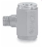
ill.8: Typical miniature force sensor.
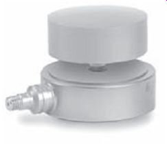
ill.9: Typical impact force sensor.
Impact - Impact style sensors are specifically designed for impact force measurements. The sensor is typically mounted in a freestanding manner with the impact cap directed toward the oncoming object with which it will collide.
Applications include crash testing, wire crimping and metal forming, machinery studies, impact testing, drop testing, and laboratory shock test machines.
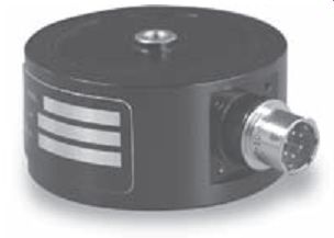
Rings - Ring sensor configurations measure dynamic compression. Tension measurements are also possible if the unit has been installed with proper pre-load. The through-hole mounting supports platform, integrated link, and support style installations using either a through bolt or the supplied stud. Tension range is dependent upon the amount of applied pre-load and strength of mounting stud used. Applications include tablet presses, stamping, punching and forming operations, balancing, machinery studies, and force-controlled vibration testing.
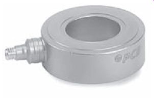
ill.10: Typical ring force sensor.
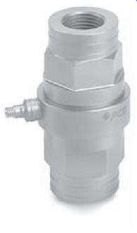
ill.11: Typical link force sensor.
Links - Link style sensors measure dynamic compression and tension. They are constructed using a force ring that is under compressive pre-load between threaded mounting hardware. The threaded mounting on both ends of the sensor supports integrated link style installations. Applications include tablet presses, tensile testing, stamping, punching and forming operations, balancing, machinery studies, and force-controlled vibration testing.
Multi-component - Multi-component sensors permit simultaneous measurement of dynamic force vector components in three orthogonal directions. Additionally, some sensors have been designed to measure moments as well. The through-hole mounting supports platform, integrated member, and support style installations using either a through bolt or the supplied stud. Applications include machine tool cutting forces, stamping, punching and forming operations, machinery studies, and force controlled vibration testing.
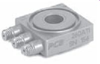
ill.12: Typical multi-component force sensor.
Applicable Standards
The basic design of quartz-based force sensors is not governed by a specific standard. However, applicable standards do exist for calibration and certification. Most manufacturers comply or conform to standards such as ISO 10012-1 (former MIL- STD-45662A), ISO 9001 and ISO/IEC 17025.
Latest and Future Developments
The basic design of modern quartz force sensors has not changed significantly since the 1960's. New applications have driven the continued development of the mechanical packaging of this technology to fit specific applications. While improvements have been made in the performance and manufacturability, the basic design has not changed.
Major Manufacturers
PCB Piezotronics, Inc. - 3425 Walden Avenue, Depew, NY 14043
Kistler Instrument Corporation - 75 John Glenn Drive, Amherst, NY 14228
Dytran Instruments, Inc. - 21592 Marilla St., Chatsworth, CA 91311
Endevco Corporation - 30700 Rancho Viejo Rd., San Juan Capistrano, CA 92675
Strain Gage Sensors
Technology Fundamentals
Sensors based on foil strain gage technology are ideally designed for the precise measurement of a static weight or a quasi-dynamic load or force. The design of strain gage-based sensors consists of specially designed structures that perform in a predictable and repeat able manner when a force, load or weight is applied.
The applied input is translated into a voltage by the resistance change in the strain gages, which are intimately bonded to the transducer structure. The amount of change in resistance indicates the magnitude of deformation in the transducer structure and hence the load that is applied.
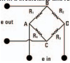
ill. 3-1: Typical Wheatstone bridge configuration.
The strain gages are connected in a four-arm Wheatstone bridge configuration, which acts as an adding and subtracting electrical network and allows for compensation of temperature effects as well as cancellation of signals caused by extraneous forces.
A regulated 5 to 20 volt DC or AC rms excitation is required and is applied between A and D of the bridge. When a force is applied to the transducer structure, the Wheat stone Bridge is unbalanced, causing an output voltage between B and C proportional to the applied load.
Most load cells follow a wiring code established by the Western Regional Strain Gage Committee as revised in May 1960. The code is as follows:
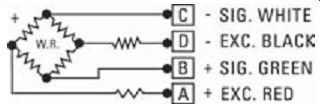
ill. 3-2: Standard electrical connection color code.
Most load cells comply with the Axis and Sense Definitions of NAS-938 (National Aerospace Standard-Machine Axis and Motion) nomenclature and recommendations of the Western Regional Strain Gage Committee. These axes are defined in terms of a "right handed" orthogonal coordinate system as shown below. A (+) sign indicates force in a direction which produces a (+) signal voltage and generally defines a tensile force. The primary axis of rotation or axis of radial symmetry of a load cell is the z axis, as defined by the following:
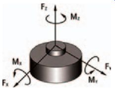
ill. 3-3. Load cell axis definitions.
Sensor Types
The most critical mechanical component in any strain gage-based sensor is the "spring element." In general terms, the spring element serves as the reaction mechanism to the applied force, load or weight. It also focuses it into a uniform, calculated strain path for precise measurement by the bonded strain gage. Three common structure designs used in the industry are bending beam, column and shear.
Bending Beam
Sensor spring elements that employ the bending beam structure design are the most common. This is because the bending beam is typically a high-strain, low force structural member that offers two equal and opposite surfaces for strain gage placement. The bending beam design is typically used in lower capacity load cells.
Column
The column type load cell is the earliest type of strain gage transducer. Although simple in its design, the column spring element requires a number of design and application considerations. The column should be long enough with respect to its cross section so that a uniform strain path will be applied to the strain gage. In application, the end user must beware of second-order effects, as the column load cell is susceptible to the effects of off-axis loading.
Shear-Web
The principle of a shear-web load cell typically takes the form of a cantilever beam that has been designed with a cross section larger than normal with respect to the rated load to be carried in order to minimize structure deflection. Under this condition, the surface strain along the top of the beam would be too low to produce an adequate electrical output from the strain gage. However, if the strain gages are placed on the sides of the beam at the neutral axis, where the bending stress is zero, the state of stress on the beam side is one of pure shear, acting in the vertical and horizontal direction.
ill.4: Bending beam structure.
ill.6: Shear-web structure.
ill.5: Column Structure.
Classification
General Purpose
General-purpose load cells are designed for a multitude of applications in the automotive, aerospace, and industrial markets. The general-purpose load cell, as the name implies, is designed to be utilitarian in nature. Within the general-purpose load cell market there are several distinct categories: precision, universal, weigh scale, and special application. Universal load cells are the most common in industry.
Fatigue Rated
Fatigue rated load cells are specially designed and manufactured to withstand millions of cycles. Many manufacturers utilize premium fatigue resistant steel and special processing to insure mechanical and electrical integrity as well as accuracy. Fatigue rated load cells typically are guaranteed to last 100 million fully reversed cycles (full tension through zero to full compression). An added benefit of fatigue rated load cells is that they are extremely resistant to extraneous bending and side loading forces.
Special Application
Special application load cells are load cells that have been designed for a specific unique force measurement task. Special application load cells can be single axis or multiple axes. They include but are not limited to:
• Pedal Effort
• Seat Belt
• Steering Column
• Crash Barrier
• Hand Brake
• Road Simulator
• Tow Ball
• Femur
• Skid Trailer
• Bumper Impact
• Tire Test
• Gear Shift
Selecting and Specifying
Selecting and specifying a strain gage-based sensor is primarily application driven. Application considerations typically include environmental concerns, the magnitude of the force, load, or weight to be measured, accuracy, size constraints, mechanical integration, present extraneous forces or loads, and certification requirements. Given the multitude of application requirements, most manufacturers offer a range of models to fit typical applications. These include:
General Purpose - General-purpose load cells are suitable for a wide range of general force measurement applications, including weighing, dynamometer testing, and material testing machines. Most of these designs operate in both tension and compression, and offer excellent accuracy and value.
ill.7: Typical general-purpose load cell.
Fatigue Rated - Fatigue rated load cells are specifically designed for fatigue testing machine manufacturers and users, or in any application where high cyclic loads are present. All fatigue rated load cells are guaranteed against fatigue failure for over 100 million fully reversed cycles. These rugged load cells are manufactured using premium, fatigue-resistant, heat treated steels. Internal flexures are carefully designed to eliminate stress concentration areas. Close attention is paid to the proper selection and installation of internal strain gages and wiring to ensure maximum life. Fatigue rated load cells are available in a variety of configurations.
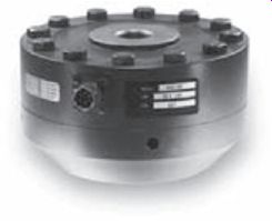
ill.8: Typical fatigue rated load cell.
Hollow, Washer, Button - Hollow compression load cells, load washers and load buttons are popular choices when the application requires a compact sensor.
These sensors are available in a wide range of sizes and capacities. Hollow compression load cells are useful for applications requiring a load to pass directly through the load cell itself. Load washers may be used to determine clamping forces with respect to applied torques on fasteners. Load buttons have an integral, spherical loading surface and are commonly used for compressive loading in production and testing applications.
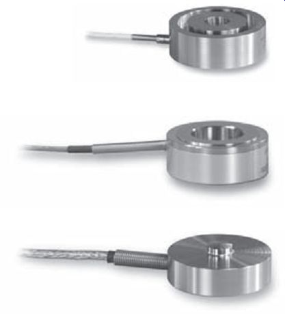
ill.9: Typical hollow load cell.
ill.10: Typical washer load cell.
ill.11: Typical button load cell.
Multi-component - These are sensors that measure multiple forces and moments simultaneously with a single transducer. Multi-component applications include fatigue testing machines, tire uniformity testing and automotive testing requirements. Typically separate receptacles or cables are provided for each axis, or channel of measurement. A careful structural analysis is required to isolate the forces and moments, which result in cross-talk. A variety of configurations and combinations of force and moment measurements are available.
Applicable Standards
The basic design of strain gage-based load cells is not governed by a specific standard. However, individual applicable standards do exist for calibration and certification of strain gage-based sensors that are used for specific measurement of a force, load, or weight.
Strain gage sensors used for measurement of a weight are governed by more specific applicable standards than sensors used for measurement of a load or a force, as strain gage sensors used to measure a weight are typically used for trade or sale of goods.
These standards are typically: Factory Mutual, OMIL, and Underwriters Laboratory.
Most manufacturers comply or conform to standards such as ISO 10012-1 (former MIL-STD-45662A), ISO 9001 and ISO/IEC 17025.
Latest and Future Developments
The basic design of strain gage-based force, load, or weight sensors has not changed significantly since the original development in the 1950s. Several manufacturers have recently added on-board electronics for signal conditioning at the sensor itself. This improves the overall quality of the sensor and reduces the system cost. Typical conditioned outputs that are available include voltage and current output options.
TEDS, which stands for "Transducer Electronics Data Sheet," is based on IEEE P1451, which is an emerging standard defining the architecture and protocol for compiling and addressing nonvolatile memory that is embedded within an analog measurement sensor. TEDS allows the user to retrieve specific information such as manufacturer name, sensor type, model number, serial number, and calibration data as well as write information such as channel ID, location, position, direction, tag number, etc. Some manufacturers are offering sensors with the TEDS feature with the overall intent of simplifying and reducing the customer's set up time and reducing errors.
Future developments within load cells and force sensors will most likely include wire less technology for transmission of digitized data over short distances. Development of this technology is underway. However, cost will be a major hurdle to overcome.
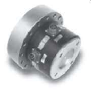
ill. 24: Typical multi-component load cell.
Other future developments may include digital temperature compensation.
Major Manufacturers:
PCB Piezotronics, Inc. - 3425 Walden Avenue, Depew, NY 14043 Lebow Products - 1728 Maplelawn Road, Troy, MI 48084 Interface, Inc. - 7401 East Butherus Drive, Scottsdale, AZ 85260 Sensotec - 2080 Arlingate Lane, Columbus, OH 43228 Tedea Huntleigh - 677 Arrow Grand Circle, Covina, CA 91722 HBM, Inc. - 19 Bartlett Street, Marlborough, MA 01752
NEXT: Humidity Sensors
PREV: