AMAZON multi-meters discounts AMAZON oscilloscope discounts
1. Humidity
Humidity is defined as the water vapor content in air or other gases. Humidity is usually measured in terms of absolute humidity (the ratio of the mass of water vapor to the volume of air or gas), dew point (the temperature and pressure at which a gas begins to condense into a liquid), and relative humidity, or RH (the ratio of the moisture content of air compared to the saturated moisture level at the same temperature or pressure).
Thermal conductivity humidity sensors, also known as absolute humidity sensors, are capable of measuring absolute humidity using a system that employs two thermistors in a bridge connection, even at high temperatures or in polluted environments.
Since the early 1960s, chilled mirrors have been used to measure dew point, but the development of thin film capacitive sensors now allows measurement of dew points at temperatures as low as -40°F at far less cost and with greater accuracy.
Relative humidity was once determined by measuring the change in moisture absorption in silk, human hair, and later, nylon and synthetics. Mechanical methods for measuring RH were introduced in the 1940s. Recently, polymer-based resistive and capacitive sensors have been developed.
2. Sensor Types and Technologies
Recent developments in semiconductor technology have made possible humidity sensors that are highly accurate, durable, and cost effective. The most common humidity sensors are capacitive, resistive, and thermal conductivity. The following sections discuss how each sensor type is constructed and used to measure humidity.
Capacitive RH Sensors
Capacitive RH sensors are used widely in industrial, commercial, and weather telemetry applications. They dominate both atmospheric and process measurements and are the only types of full-range RH measuring devices capable of operating accurately down to 0% RH. Because of their low temperature effect, they are often used over wide temperature ranges without active temperature compensation.
In a capacitive RH sensor, change in dielectric constant is almost directly proportional to relative humidity in the environment. Typical change in capacitance is 0.2-0.5 pF for 1% RH change. Bulk capacitance is between 100 and 500 pF at 50% RH at 25°C. These sensors have low temperature coefficient and can function at high temperatures up to 200°C. They are able to fully recover from condensation and resist chemical vapors. Response time ranges from 30 to 60 seconds for a 63% RH step change.
Thermoset polymer-based capacitive RH sensors directly detect changes in relative saturation as a change in sensor capacitance with fast response, high linearity, low hysteresis, and excellent long-term stability. Relative saturation is the same as ambient relative humidity when the sensor is at ambient temperature. Because this is almost always the case, sensor capacitance change is then a measure of RH change.
These sensors use an industrially proven thermoset polymer, three layer capacitance construction, platinum electrodes and except for high temperature versions, on-chip silicon integrated voltage output signal conditioning.
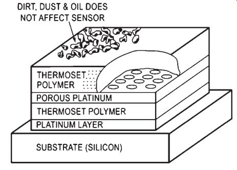
Fig. 2-1: This relative humidity sensor has three-layer capacitance
construction and consists of thermoset polymer, platinum electrodes, and
a silicon chip with integrated voltage output signal conditioning.
In operation, water vapor in the active capacitor's dielectric layer equilibrates with the surrounding gas. The porous platinum layer shields the dielectric response from external influences while the protective polymer overlay provides mechanical protection for the platinum layer from contaminants such as dirt, dust and oils. A heavy contaminant layer of dirt will slow down the sensor's response time because it will take longer for water vapor to equilibrate in the sensor.
Thermoset polymer-based capacitive sensors, as opposed to thermoplastic-based capacitive sensors, allow higher operating temperatures and provide better resistivity against chemical liquids and vapors such as isopropyl, benzene, toluene, formaldehydes, oils, common cleaning agents, and ammonia vapor in concentrations common to chicken coops and pig barns. In addition, thermoset polymer RH sensors provide the longest operating life in ethylene oxide-based (ETO) sterilization processes.
Thermoset thin film polymer capacitive sensors have been shown to have an almost ideal response to RH, as opposed to absolute moisture (i.e., water vapor pressure). This response is due to the driving force free energy for absorption, G:
G = R T Ln(P/P0)
where
G = driving force
R = gas constant
P = partial water vapor pressure
P_0 = saturation water vapor pressure
P/P_0 is the same as ambient RH when the sensor is at ambient temperature. The relative saturation level driving sensor response is 100% at the sensor temperature T.
Research has also demonstrated that the RH sensor calibration in air applies to relative saturation measurement in oil to within 0.3% (a result which can be extended to other chemically compatible liquids).
Resistive Humidity Sensors
Resistive humidity sensors measure the impedance change, which usually has an inverse exponential relationship to humidity. Typically, the impedance change of a medium such as a conductive polymer, salt, or treated substrate is measured.
The first mass-produced humidity sensor was the Dunmore type. Produced in 1940, it is still widely used in precision air conditioning controls and for monitoring transmission lines, antennas, and waveguides used in telecommunications.
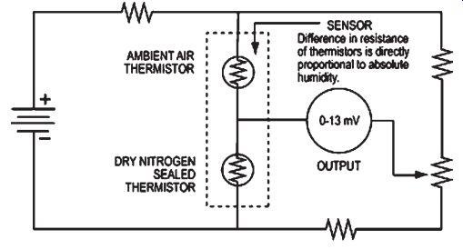
----: Thermal conductivity (or absolute) humidity sensors.
3. Selecting and Specifying Humidity Sensors
The following sections address what differentiates each sensor from another, including temperature, accuracy, and interchangeability. The advantages and disadvantages of each sensor type are also identified.
Selecting Humidity Sensors
Important considerations when selecting a humidity sensor include:
¦ Accuracy
¦ Interchangeability
¦ Repeatability
¦ Stability
¦ Condensation recovery
¦ Contaminant resistance
¦ Size and packaging
¦ Cost effectiveness
¦ Cost to replace sensor
¦ Calibration
¦ Complexity and reliability of signal conditioning and data acquisition circuitry
In general, environmental conditions for the given application will dictate the choice of sensor.
Selecting Capacitive RH Sensors
Applications for capacitive RH sensors are wide ranging, including:
¦ Automotive onboard devices such as windshield defoggers
¦ Computer printers
¦ Medical devices such as ventilators and incubators
¦ Appliances such as microwave ovens, refrigerators, and clothes dryers
¦ HVAC
¦ Recorders and data loggers
¦ Leak detection
¦ Weather stations
¦ Industrial and food processing equipment
¦ Environmental test chambers
Taking advantage of cutting-edge principles in semiconductor design, many capacitive sensors have minimal long-term drift and hysteresis. Incorporating a complementary metal oxide semiconductor (CMOS) timer pulses the sensor producing near-linear voltage output. .
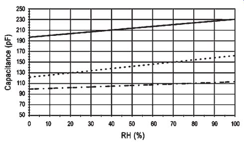
FIG. 3.1: Voltage output with a CMOS timer.
Typical uncertainty is ±2% RH from 5% to 95% RH using two-point calibration. The capacitive effect of the connecting cable relative to the small capacitance changes of the sensor limits the distance the sensing element can be located from the signal conditioning circuitry to a practical range of less than 10 feet.
Laser trimming reduces variance ±2%, improving direct field interchangeability. Computer recalibration programs are also capable of compensating for sensor capacitance from 100 to 500 pF.
Capacitive RH sensors are not linear below a few percent RH, which is why many sensors incorporate a dew-point measurement system that employs microprocessor based circuitry to store calibration data. This development has reduced the cost of hygrometers and transmitters in HVAC and weather telemetry applications.
Advantages
¦ Near-linear voltage output
¦ Wide RH range and condensation tolerance
¦ Interchangeable, if laser trimmed
¦ Stable over long-term use
Disadvantages
¦ Distance from sensing element to signal conditioning circuitry limited
Selecting Resistive Humidity Sensors
Resistive sensors are small, low-cost humidity sensors that provide long-term stability and are highly interchangeable. They are suitable for many industrial, commercial, and residential applications, especially control and display products.
Resistive sensors respond nonlinearly to humidity changes, but they may be linearized by analog or digital methods. Typical variable resistance ranges from a few kilohms to 100 MV. Nominal excitation frequency is from 30 Hz to 10 kHz.
RH sensors are highly interchangeable (within ±2% RH). Electronic signal conditioning circuitry can be calibrated at a fixed RH point, eliminating the need for humidity calibration standards. Accuracy can be tested in an RH calibration chamber or by a computer-based system referenced to a standardized environment. Resistive sensors have a nominal operating temperature of -40°C to 100°C.
Life expectancy is less than five years in residential and commercial applications, but exposure to contaminants may cause premature failure. Resistive sensors also tend to shift values during exposure to condensation when water-soluble coatings are used.
Advantages
¦ No calibration standards, so highly interchangeable and field replaceable
¦ Long-term stability
¦ Usable from remote locations
¦ Small size
¦ Low cost
Disadvantages
¦ Exposure to chemical vapors and contaminants may cause premature failure
¦ Values may shift when water-soluble coatings are used
Selecting Thermal Conductivity Humidity Sensors
Thermal conductivity humidity sensors are commonly used in appliances, including clothes dryers and microwave ovens. They are used in many industrial applications including wood-drying kilns, drying machinery, pharmaceutical production, cooking, and food dehydration.
Constructed with glass, semiconductor material, high-temperature plastics, and aluminum, thermal conductivity sensors are very durable and resistant to chemical vapors.
They provide better resolution than capacitive and resistive sensors in temperatures greater than 200°F. Typical accuracy is +3 g/m^3, which converts to approximately ±5% RH at 40°C and ±0.5% RH at 100°C.
Advantages
¦ Very durable
¦ Work well in corrosive and high-temperature environments up to 575°F
¦ Better resolution than capacitive and resistive sensors
Disadvantages
¦ Responds to any gas with thermal properties different than dry nitrogen, which may affect measurement.
4. Applicable Standards
Standards Bodies
American National Standards Institute (ANSI): http://www.ansi.org
A private, non-profit organization responsible for administering the U.S. voluntary standardization and conformity assessment system.
American Society of Testing and Materials (ASTM): http://www.astm.org One of the largest voluntary standards development organizations in the world.
Develops and publishes voluntary consensus standards for materials, products, systems, and services.
Canadian Standards Association (CSA): http://www.csa.ca
Not-for-profit membership-based association serving business, industry, government, and consumers in Canada and around the world. Develops standards for enhancing public safety and health, advancing the quality of life, helping to preserve the environment, and facilitating trade.
Instrumentation, Systems, and Automation Society (ISA): http://www.isa.org
Helps advance the theory, design, manufacture, and use of sensors, instruments, computers, and systems for measurement and control in a variety of applications.
International Electrotechnical Commission (IEC): http://www.iec.ch
Prepares and publishes international standards for all electrical, electronic, and related technologies.
International Organization for Standardization (ISO): http://www.iso.ch/
A network of national standards institutes from 146 countries working in partnership with international organizations, governments, industry, business and consumer representatives.
Japanese Standards Association (JSA): http://www.jsa.or.jp/default_english.asp
Objective is "to educate the public regarding the standardization and unification of industrial standards, and thereby to contribute to the improvement of technology and the enhancement of production efficiency." National Institute of Standards and Technology (NIST): http://www.nist.gov Founded in 1901, NIST is a non-regulatory federal agency within the U.S. Commerce Department's Technology Administration. Its mission is to develop and promote measurement, standards, and technology to enhance productivity, facilitate trade, and improve the quality of life.
Industry Organizations
American Society for Quality (ASQ): http://www.asq.org/ Purpose is to improve workplace and communities by advancing learning, quality improvement, and knowledge exchange. Advises the U.S. Congress, government agencies, state legislatures, and other groups and individuals on quality-related topics.
International Measurement Confederation (IMEKO):
Non-governmental federation of 36 member organizations. Promotes inter national interchange of scientific and technical information in the field of measurement and instrumentation and the international cooperation among scientists and engineers from research and industry.
National Conference of Standards Laboratories International (NCSL International): http://www.ncsli.org/
A professional association for individuals involved in all aspects of measurement science.
Underwriter's Laboratories (UL): http://www.ul.com
An independent, not-for-profit product-safety testing and certification organization.
5. Interfacing and Design Information
Temperature and Humidity Effects
The output of all absorption-based humidity sensors (capacitive, bulk resistive, conductive film, etc.) is affected by both temperature and %RH. Because of this, temperature compensation is used in applications that call for either higher accuracy or wider operating temperature ranges.
When calibrating a humidity sensor to compensate for temperature, it is best to make the temperature measurement as close as possible to the humidity sensor's active area--i.e., within the same moisture microenvironment. This is especially true when combining RH and temperature as a method for measuring dew point. Industrial grade humidity and dew point instruments incorporate a 1000-ohm platinum RTD on the back of the ceramic sensor substrate for unmatched temperature compensation measurement integrity. No on-chip signal conditioning is provided in these high temperature sensors.
Voltage Output
A humidity sensor with a relative humidity integrated circuit (RHIC) has a linear voltage output that is a function of Vsupply, %RH and temperature. The output is ''ratio metric,'' so as the supply voltage rises, the output voltage rises in the same proportion.
A surface plot of the sensor behavior for temperatures between 0°C and 85°C.
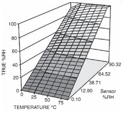
FIG. 5.1: Surface plot of sensor behavior.
This surface plot is well approximated by a combination of two equations:
1. A ''Best Fit Line at 25°C,'' or a similar, sensor-specific equation at 25°C. The sensor independent ''typical'' Best Fit Line at 25°C (bold line in graph) is:
Vout J Vsupply (0.0062 (%RH) + 0.16)
A sensor-specific equation can be obtained from an RH sensor printout. The printout equation assumes Vsupply J 5VDC and is included or available as an option on the sensors.
2. A sensor-independent equation, which corrects the %RH reading (from the Best Fit Line Equation) for temperature, T:
True RH = (%RH)/(1.0546 - .00216 T); T = °C
Or True RH = (%RH)/(1.093 - .0012 T); T = °F
The previous equations match the typical surface plot (Best Fit Line at 25°C) or the actual surface plot (sensor-specific equation at 25°C) to within the following tolerances:
±1% for T>20°C
±2% for 10°C<T<20°C
±5% for T<10°C
Dewpoint instruments may account directly for a sensor-specific version of the surface plot via a look-up table.
Note: Convert the observed output voltage to %RH values via the first equation before applying the second equation.
Condensation and Wetting
Condensation occurs whenever the surface temperature of the sensor's active area drops below the ambient dew point of the surrounding gas. Condensation forms on the sensor (or any surface) even if the surface temperature only momentarily drops below the ambient dew point. Small temperature fluctuations near the sensor can unknowingly cause condensation to form when operating at humidity levels above 95%.
While quick to condense, water is slow to evaporate in high humidity conditions (i.e., when the surface temperature of the sensor is only slightly above the ambient dew point.) Because of this, a sensor's recovery period from either condensation or wet ting is much longer than its normal time response. During recovery, the sensor outputs a constant 100% RH signal regardless of the ambient RH.
When an application calls for continuous monitoring of RH at humidity levels of 90% and above, take steps to avoid intermittent condensation. Some strategies are:
1. Maintain a good air mixing to minimize local temperature fluctuations.
2. Some sensors use a sintered stainless steel filter to protect the sensor from splashing. A hydrophobic coating further suppresses condensation and wetting in rapidly saturating and de-saturating or splash-prone environments.
3. Heat the RH sensor so that the active area is hotter than the local dew point.
This can be done through an external heater or by self heating of the CMOS RH chip by operating it at a higher supply voltage.
Note: Heating an RH sensor above ambient temperature changes its calibration and makes it sensitive to thermal disturbances such as airflow.
Integrated Signal Conditioning
All RH sensors quickly recover from condensation or wetting with no shift in calibration. However, after 24-hour or longer exposures to either high (>95%) RH or continuous condensation, an upward shift of 2% to 3% RH may occur. This shift is repeatable and can be reversed by placing the sensor in a low (10%) RH environment for a 10-hour period.
Silicon integrated humidity sensors incorporate signal conditioning circuitry on-chip with the sensing capacitor. These RHIC humidity sensors are laser trimmed so that at Vsupply J 5 V, the output voltage typically spans 0.8 V to 3.9 V for the 0% RH to 100% RH range at 25°C. (Sensor-specific calibration data printouts and Best Fit Lines at 25°C are either included or available as an option on these sensors.)
RHIC-based sensors are factory calibrated, micro-power devices with either individual calibration and/or good unit-to-unit interchangeability. These features help OEM manufacturers avoid in-house humidity calibration costs and extend battery life in portable instruments. Improved accuracy can be obtained by tuning system electronics to account for an individual sensor's Best Fit Line at 25°C.
Interchangeability defines the range of voltages for any population of sensors at an RH point. An interchangeability of ±5% @ 0%RH is compared to the baseline output for the RHIC chip, which is 0.8 V to 3.9 V (0 to 100% RH) with an excitation voltage of 5 VDC.
If you take the baseline slope, 0.031 V/%RH times ± 5%RH you get ± 0.155 V. This means that the output voltage for this device is 0.8 V ± 0.155 V or a range of 0.645 V to 0.955 V. When exposed to an RH of 0%, the output of the entire population of sensors will fall within this range.
Interchangeability increases with increasing RH since the RHIC die is actively trimmed only at 0% RH. Trimming at other RH values is impractical.
Interchangeability lets you lower design cost by avoiding calibrating your system to each individual sensor. The RHIC sensor keeps its interchangeability and accuracy advantages at higher humidity.
Accuracy is based on the specific calibration curve for any individual sensor and equals ±2% RH. For example, if a specific sensor has an output voltage of .850 V at 0%RH (5 VDC supply assumed), then this sensor should always output this voltage ±0.062 V*** or a range of 0.788 V to 0.912 V. Accuracy equals interchangeability ±2% when you don't calibrate your system to each sensor. If you calibrate to each RHIC sensor, then total accuracy can be ±1-2% RH.
NEXT: Machinery Vibration Monitoring Sensors
PREV: