AMAZON multi-meters discounts AMAZON oscilloscope discounts
1. Introduction
The ears and hands are very subjective when sensing vibrations. The days of judging a machine's health by sound and touch (or listening to a screwdriver placed against the machine) have quickly transitioned to a more scientific approach, allowing data trending and early prediction of machinery failure.
In order to make objective, informed decisions, most measurement engineers prefer to have consistent, trendable data that can be regularly referred to. Machinery vibration sensors, along with a readout instrument, can provide this objective information, allowing for a more precise assessment of machinery health.
Due to the piezoelectric accelerometer's wide frequency response, it is an excellent sensor to replace human subjectivity in most machinery health monitoring. In addition, permanent mounting of these sensors provides continuous monitoring or shut-down functions for critical machinery. This allows plant and production management to be predictive in their maintenance strategy. The result is cost-effective, scheduled down time to repair equipment as opposed to a reactive approach toward maintenance, which often involves expensive loss of production and repairs. In the future, it is expected that a greater percentage of machines will continue to be monitored for earlier prediction of failures. This will allow maintenance personnel to focus on the smaller percentage of machines actually having problems as opposed to manually monitoring and wasting expensive labor on healthy machinery.
Some key applications and industries in which machinery vibration sensors are utilized are as follows:
¦ Aluminum Plants
¦ Automotive Manufacturing
¦ Balancing
¦ Bearing Analysis & Diagnostics
¦ Bearing Vibration Monitoring
¦ Bridges and Civil Structures
¦ Coal Processing
¦ Cold Forming Operations
¦ Concrete Processing Plants
¦ Condition Based Monitoring
¦ Compressors
¦ Cooling Towers
¦ Crushing Operations
¦ Diagnostics of Machinery
¦ Engines
¦ Floor Vibration Monitoring
¦ Food, Dairy & Beverage
¦ Foundations
¦ Gearbox Monitoring
¦ Geological Exploration
¦ Heavy Equipment & Machinery
¦ Helicopters
¦ Hull Vibration Monitoring
¦ HVAC Equipment
¦ Impact Measurements
¦ Impulse Response
¦ Machine Tools
¦ Machinery Condition Monitoring
¦ Machinery Frames
¦ Machinery Mount Monitoring
¦ Machinery Vibration Monitoring
¦ Manufacturing
¦ Mining
¦ Modal Analysis
¦ Motor Vibration
¦ Off-Road Equipment
¦ Paper Machinery Monitoring
¦ Petrochemical
¦ Pharmaceutical
¦ Power Generation
¦ Predictive Maintenance
¦ Printing
¦ Pulp & Paper
¦ Pumps
¦ Quality Control
¦ Seismic Monitoring
¦ Shipboard Machinery
¦ Shock Measurements
¦ Shredding Operations
¦ Site Vibration Surveys
¦ Slurry Pulsation Monitoring
¦ Spindle Vibration & Imbalance
¦ Squeak & Rattle Detection
¦ Steel & Metals
¦ Structure-Borne Noise
¦ Structural Testing
¦ Submersible Pumps
¦ Transportation Equipment
¦ Turbines
¦ Turbomachinery
¦ Underwater Pumps
¦ Vibrating Feeders
¦ Vibration Control
¦ Vibration Isolation
¦ Water Treatment Plants
¦ Wastewater Treatment Plants
The typical faults that machinery vibration sensors are able to detect, along with their approximate percent of occurrence, are as follows:
Imbalance 40%
Misalignment 30%
Resonance 20%
Belts and Pulleys 30%
Bearings 10%
Motor Vibration 8
Pump Cavitation 5
Accelerometers are the most common machinery vibration sensor used today. Applications for accelerometers in the industrial sector are primarily focused on extending service life of machinery by predicting failures and allowing maintenance to be conducted in a planned manner. By doing so, operators can make more intelligent decisions about spare parts purchases and keep critical equipment up-and-running longer and faster to increase product output and profitability. Accelerometers are ideal for small to medium sized machines with rolling element bearings, where the casing and bearings move with the rotor. In this case, an accelerometer (sometimes referred to as a seismic transducer) on the bearing housing will also be a good indicator of shaft motion. They are convenient to use and easily attach directly to the outside of the bearing housing. (These can still be used on journal bearing machines on the out side casings, but the motion will be smaller on the outside casing because of the mass of the casing and the reduced transmissibility through the fluid film.) Technically speaking, accelerometers are transducers that are designed to produce an electrical output signal that is proportional to applied acceleration. Several sensing technologies are utilized to construct accelerometers, including resistive (foil or silicon strain gages), capacitive and piezoelectric. Resistive and capacitive types possess the ability to measure constant acceleration, such as that of earth's gravity, and are generally only used for measuring very low frequency vibration, such as that encountered with massive, slow-speed rollers. On the other hand, piezoelectric types possess an extremely wide frequency range and are suited to accurately measure most other types of vibration. They are ideal for machinery vibration monitoring and are recommended for nearly every industrial vibration application on rotating machinery.
Piezoelectric accelerometers are generally durable, protected from contamination, impervious to extraneous noise influences, and are easy to implement. Accelerometers that are designed with these features are classified as Industrial Accelerometers and are normally suitable for use in rigorous industrial, field or submersible environments.
2. Technology Fundamentals
Piezoelectric accelerometers rely on the piezoelectric effect. This basically means that the internal sensing material will provide an electrical charge when squeezed or strained.
There are several methods used to stress the piezoelectric material. (All of these methods utilize a seismic mass attached to the sensing material and rely on Newton's Second Law: Force = Mass × Acceleration. Refer to SECTION 5 for additional information.) These methods are categorized in the following terms that define the geometry of the sensing element-compression, flexural, and shear. Each has advantages and disadvantages; however, for best overall performance in industrial machinery vibration applications, leading manufacturers utilize, almost exclusively, the shear structured geometry for its piezoelectric industrial accelerometers.
Additional circuitry can be added to enhance or tune the output signal for specific purposes. Such enhancements include filtering, rms conversion, 4-20 mA transmitters, integrators, and TEDS (Transducer Electronic Data Sheet-an on-board, addressable memory with stored, self-identifying information).
To properly operate, sensors with built-in electronics require a constant current power source. Normally, this constant current power supply is built into the industrial readout equipment (data collector or on-line monitor). If it is not included, sensor manufacturers offer a variety of different power supplies.
While the fundamental technology associated with accelerometers is very similar, the specific design of the sensor is critical. Industrial accelerometers have to endure severe environments and tough operating conditions. In order to achieve these requirements, there are several design and construction characteristics to be aware of.
These design criteria include:
Welded, stainless steel housing - This proven, corrosive-resistant material stands up well against dirt, oil, moisture, and harsh chemicals. Stainless steel is also non-magnetic, which minimizes errors induced when used in the vicinity of electric motors and other sources of electromagnetic interference. For durability, all mating housing parts are precision laser welded. No epoxies are used which can eventually fatigue or cause leaks.
Internal Faraday shield - Accelerometers that utilize an internal electrical shield to guard against radio frequency interference (RFI), electromagnetic interference (EMI), and other extraneous noise influences. The result is an electrically case-isolated sensing element that is insulated from ground, which also insures that there won't be any ground loops in the measurement system that can cause signal drift, noise, and other hard-to-trace electrical problems.
Durable, military style electrical connectors or sealed, integral cables - It is highly recommended to use electrical connectors that offer a true hermetic seal with glass-to-metal fusing of connector pins and shells. All connectors should be laser welded to the sensor housing. Sensors with integral cables incorporate hermetic feed-through pins and high-pressure, injection-molded sealing of the cable to a metallic shell that is laser welded to the sensor housing. Integral polyurethane jacketed cables offer 750 psi submersibility along with excellent pull strength and strain relief characteristics.
Rugged Cables - Interconnect cables should utilize shielded, twisted conductor pairs and an outer jacket material that will survive exposure to most industrial media, or excessive temperatures present in the environment in which it will be used. Stainless steel, armored cables are recommended for installations where machined debris or chips may damage cable jackets, or where cables have the potential of being stepped on or pinched. Electrical connectors for cables are offered in a variety of styles and configurations to suit the application. Take care to note the temperature rating of the connector and material of construction. Environmentally sealed cable connectors provide a boot to protect the integrity of the connection in outdoor installations or during wash down episodes.
3. Accelerometer Types
Low-Cost, Industrial ICP Accelerometers for Permanent Installation
Low-cost, industrial ICP accelerometers are recommended for permanent installation onto machinery to satisfy vibration trending requirements in predictive maintenance and condition monitoring applications. In addition to sound design and high volume manufacturing techniques, lower cost is achieved by relaxing the tolerance on sensitivity from unit to unit and by calibrating at only one reference frequency point, typically 100 Hz. Measurement accuracy is compromised only if the sensor's nominal sensitivity is used. If the provided single-point sensitivity is used, accuracy is very good.
Since low-cost sensors carry a wider sensitivity tolerance, the actual measurement obtained using the nominal sensitivity value may not be as quantitatively accurate as could be achieved if one uses the supplied reference sensitivity value. This disparity, however, may be irrelevant since when trending, the user is primarily interested in recognizing changes in the overall measured vibration amplitude, or frequency signature of the machinery. When comparing against previously acquired data obtained with the same sensor in the same location, the excellent repeatability of these piezoelectric vibration sensors becomes the vital attribute for successful trending requirements. The user benefits by being able to employ a lower cost sensor, which in turn makes monitoring additional measurement points a more attractive undertaking.
Low-Frequency Industrial ICP Accelerometers
Low-frequency accelerometers are generally designed for use on large slow-rotating equipment. Applications include:
¦ Vibration measurements on slow rotating machinery
¦ Paper machine rolls
¦ Large structures and machine foundations
¦ Large fans and air handling equipment
¦ Cooling towers
¦ Buildings, bridges, foundations, and floors
Low-acceleration levels go hand-in-hand with low-frequency vibration measurements.
For this reason, these accelerometers combine extended low frequency response with high output sensitivity in order to obtain the desired amplitude resolution characteristics and strong output signal levels necessary for conducting low-frequency vibration measurements and analysis.
The most sensitive low-frequency accelerometers are known as seismic accelerometers. These models are larger in size to accommodate their larger seismic, internal masses, which are necessary to generate a stronger output signal. These sensors have a limited amplitude range, which renders them unsuitable for many general purpose industrial vibration measurement applications. However, when measuring the vibration of slow, rotating machinery, buildings, bridges and large structures, these low-frequency, low-noise accelerometers will provide the characteristics required for successful results.
All low-frequency industrial accelerometers benefit from the same advantages offered by general-purpose industrial accelerometers including: rugged, laser-welded, stainless steel housing with the ability to endure dirty, wet, or harsh environments; hermetically sealed military connector or sealed integral cable; and a low-noise, low impedance, voltage output signal with long-distance signal transmission capability.
High-Frequency Industrial ICP Accelerometers
High-frequency accelerometers are generally used for high-speed rotating machinery.
Applications include:
¦ Vibration measurements on high-speed rotating machinery
¦ Gear mesh studies and diagnostics
¦ Bearing monitoring
¦ Small mechanisms
¦ High-speed spindles
Successful vibration measurements begin with sensors that have adequate capabilities for the requirement. If the sensor's frequency response characteristics are inadequate, the user risks corrupted or insufficient data to achieve a proper analysis and diagnosis.
For vibration monitoring, testing, and frequency analysis of high-speed rotating machinery, spindles, and gear mesh, it is imperative to utilize a sensor with a sufficient high frequency range to accurately capture the vibration signals within the bandwidth of interest. Miniature sized units are also suitable for vibration measurements on small mechanisms where sensor size and weight become important factors.
4-20 mA Vibration Sensing Transmitters
These sensors are accelerometers which have been configured to have a loop-powered, 4-20 mA output. Generally, vibration sensing transmitters provide output signals that are representative of the overall vibration. (Typically, an internal integrator is included so that the output is in velocity, such as in/sec rms or mm/s pk.) This vibration signal may be interfaced with many types of commercially available current-loop monitoring equipment, such as recorders, alarms, programmable logic controllers (PLCs) and digital control systems (DCSs).
The vibration-sensing transmitters capitalize on the use of existing process control equipment and human machine interface (HMI) software for monitoring machinery vibration and alarming of excessive vibration levels. This allows the operator to monitor machinery using the existing process control system as opposed to having to purchase specific vibration monitory software. This practice offers the ability to continuously monitor machinery and provide an early warning detection of impending failure. With this approach, existing process control technicians can monitor the vibration levels while skilled vibration specialists are called upon only in the event that the vibration signal warrants more detailed signal analysis. It is envisioned that someday machinery vibration measurements will be monitored in process facilities via 4-20 mA transmitters as widely as pressure, temperature, flow and load are currently done so today.
A choice of velocity or acceleration measurement signals are offered with a variety of amplitude and frequency ranges to suit the particular application. Most models also feature an optional analog output signal connection (raw vibration option) for con ducting frequency analysis and machinery diagnostics.
DC Response, Industrial Capacitive Accelerometers -- Applications
DC response accelerometers are generally only used on very large, slow-rotating equipment or on extremely large civil structures. Applications include:
¦ Paper machine rolls
¦ Large structures and machine foundations
¦ Cooling towers
¦ Buildings, bridges, foundations, and floors
Unlike piezoelectric accelerometers that have a low frequency limit, industrial capacitive accelerometers are capable of measuring to true DC, or 0 Hz.
Capacitive accelerometers utilize two opposed plate capacitors that share a common flexible plate in the middle. As the flexible plate responds to acceleration, differential output signals from the two capacitors are created. These signals are conditioned to reject common mode noise and combined to provide a standardized output sensitivity.
Built-in voltage regulation and optional low-power versions permit operation from a wide variety of DC power sources. The result is a sensor that is easy to implement and delivers a high integrity, low noise output signal.
DC response, industrial capacitive accelerometers offer many of the same advantages as general purpose industrial accelerometers including: rugged, laser-welded, stainless steel housing with the ability to endure dirty, wet, or harsh environments; hermetically sealed military connector or sealed integral cable; and a low noise, low impedance, voltage output signal with long distance signal transmission capability.
4. Selecting Industrial Accelerometers
There will usually be several accelerometer models that meet the required measurement parameters, so the question naturally arises, Which should be used? By answering the following questions as accurately as possible, the user will be able to determine a set of key specifications required for the accelerometer.
1. Measurement Range / Sensitivity -- Determine the maximum peak vibration amplitude that will be measured and select a sensor with an appropriate measurement range. For a typical accelerometer, the maximum measurement range is equal to ±5 volts divided by the sensitivity. For example, if the sensitivity is 100 mV/g then the measurement range is (5 V / 0.1 V/g) = ±50 g.
Allow some overhead in case the vibration is a little higher than expected. The vibration severity chart shown in Figure 4.1 may help when determine the expected measurement range.
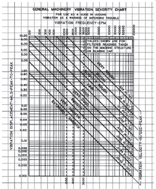
---: Vibration severity chart.
2. Frequency Range -- Determine the lowest and highest frequencies to be analyzed. If you are not sure what the upper frequency range should be, use the following table showing "Recommended Frequency Spans" as a guideline.
Table 4-1: Frequency range guidelines [Ref. 4].
Recommended Frequency Spans (Upper Frequency)
Shaft Vibration 10 × RPM
Gearbox 3 × GMF
Rolling Element Bearings 10 × BPFI
Pumps 3 × VP
Motors / Generators 3 × (2 × LF)
Fans 3 × BP
Sleeve Bearings 10 × RPM
RPM - Revolutions Per Minute
GMF - Gear Mesh Frequency
BPFI - Ball Pass Frequency Inner race
VP - Vane Pass frequency
LF - Line Frequency (60 Hz in USA)
BP - Blade Pass frequency
Select an accelerometer that has a frequency range that encompasses both the low and high frequencies of interest. In some rare cases, it may not be possible to measure the entire range of interest with a single accelerometer.
High Frequency Caution -- Many machines, such as pumps, compressors, and some spindles, generate high frequencies beyond the measurement range of interest. Even though these vibrations are out of the range of interest, the accelerometer is still excited by them. Since high frequencies are usually accompanied by high accelerations, they will often drive higher sensitivity accelerometers (100 and 500 mV/g models) into saturation causing erroneous readings. If a significant high frequency vibration is suspected or if saturation occurs, a lower sensitivity (typically 10 or 50 mV/g) accelerometer should be used. For some applications, higher sensitivity accelerometers are available with built-in low pass filters. These sensors filter out the unwanted high frequency signals and thus provide better amplitude resolution at the frequencies of interest.
To determine if you have a condition that will overdrive (saturate) the accelerometer, look at the raw vibration signal in the time domain on a data collector, spectrum analyzer, or oscilloscope. Set the analyzer for a range greater than the maximum rated output of the accelerometer. If the amplitude exceeds the maximum rated measurement range of the accelerometer (typically 5 volts or 50 g for a 100 mV/g unit), then a lower sensitivity sensor should be selected.
If the higher sensitivity sensor is used, clipping of the signal and saturation of the electronics is likely to occur. This will result in false harmonics, "ski slope" as well as many other serious measurement errors.
3. Broadband Resolution (Noise) -- Determine the amplitude resolution that is required. This will be the smaller of either the lowest vibration level or the smallest change in amplitude that must be measured. Select a sensor that has a broadband resolution value equal to or less than this value. For example, if measuring a spindle with 0.001 g minimum amplitude, choose an accelerometer with a resolution better than 1 mg. If the known vibration levels are in velocity (in/s) or displacement (mils), convert the amplitudes to acceleration (g) at the primary frequencies. Note: The lower the resolution value, the better the resolution is. Generally, ceramic sensing elements have better resolutions (less noise) than quartz based sensors.
4. Temperature Range -- Determine the highest and lowest temperatures that the sensor will be subjected to and verify that they are within the specified range for the sensor.
Temperature Transients -- In environments where the accelerometer will be subjected to significant temperature transients, quartz sensors may achieve better performance than ceramic. Ceramic sensing elements are subject to the pyroelectric effect, which can cause erroneous outputs with changes in temperature. These outputs typically occur as drift (very low frequency) and usually cause significant "ski slope" when the signal is integrated and displayed in the velocity spectrum.
5. Size -- In many cases, the style of the sensor used can be restricted by the amount of space that is available on a machine to mount the sensor. There are typically two parameters that govern which sensors will fit, the footprint and the clearance. The footprint is the area covered by the base of the sensor. The clearance is the height above the surface required to fit the sensor and cable.
As an example, a top exit sensor will require more clearance than a side exit.
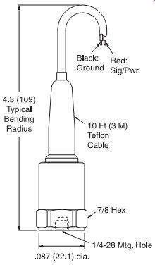
FIG. 4.2: "Top exit" accelerometer (requires more clearance).
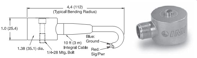
FIG. 4.3: "Side exit" accelerometer (requires less clearance).
Orientation -- Cable orientation is another consideration. Ring-style, side exit models can be oriented 360°, however, in some very tight spaces, even these may be difficult to install. For example, there may not be enough height clearance to fit a wrench to tighten the unit. In that case, a swivel mount style accelerometer may be required.
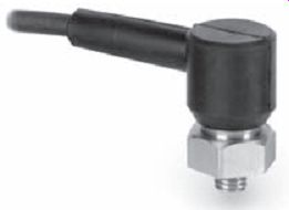
---: "Swivel mount" accelerometer.
6. Duty (Accuracy, Sensitivity Tolerance, and Safety) - The duty refers to the type of use that a sensor will see. Most typical predictive maintenance applications are either in a walk-around application, as with a portable data collector, or permanently mounted to a particular machine. In permanent mount applications, the sensor may terminate at a junction box where measurements are taken with a portable data collector or tied to an on-line monitoring system.
4-20 mA output sensors would usually be tied to existing plant systems such as a PLC.
Sensitivity Tolerance (Absolute Accuracy) -- Sensitivity tolerance is the maxi mum deviation that the actual sensitivity of an accelerometer can vary from its published nominal sensitivity and still be within specification. Most manufacturers offer accelerometers with ± 5%, ± 10%, ± 15%, and ± 20% tolerances on sensitivity. Thus, a nominal 100 mV/g sensor with a ± 5% tolerance could have an actual sensitivity between 95 and 105 mV/g. A ± 20% tolerance unit could vary between 80 and 120 mV/g. If the nominal sensitivity is used to convert the actual data to engineering units (e.g., entered into the data collection device), then a looser tolerance sensor will be less accurate, in general, than a tighter tolerance model. However, if the actual calibration value that is supplied with the sensor is used, then both readings will be equally accurate. In applications were absolute accuracy is important (e.g., in acceptance testing) then either higher tolerance sensors or the actual calibration factors should be used.
Lower tolerance sensors are typically provided with a single point calibration rather than full calibration. This, coupled with the looser tolerance, helps keep costs down and allows them to be offered at a much more economical price.
Normally, these sensors are selected for permanent mount applications where larger numbers of accelerometers are needed.
Calibration Interval -- Due to the inherent stability of quartz, accelerometers with quartz sensing elements have a longer recommended calibration interval than do ceramic sensors. The recommended time between calibrations is 1 year for ceramic sensors and 5 years for quartz. As a practical matter, how ever, it may not be possible to send ceramic sensors in for yearly recalibration.
As long as the sensor is permanently mounted and not going through severe thermal transients on a regular basis, its sensitivity should remain fairly stable. However, if it is seeing repeated shocks (as with magnetic mounting in a walk around system) or severe thermal transients, it is highly recommended that the sensor be recalibrated yearly. One advantage of quartz sensors is its long-term stability even in high shock and thermally transient environments. A typical calibration certificate is shown in FIG. 4.5.
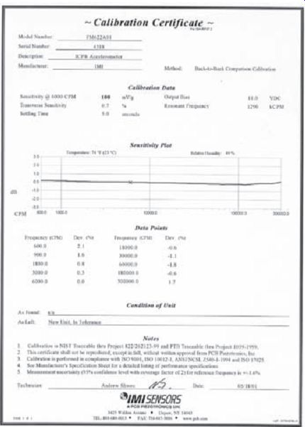
---: Typical accelerometer calibration certificate.
Accessibility, Safety, and Production Considerations -- Monitoring locations on machines are often inaccessible due to shrouds, safety requirements, space constraints, or other physical obstacles. Additionally, they may be in hazardous areas or have limited access due to pressing production schedules. In cases like these, permanent mount accelerometers should be selected. This provides a fast, easy, and safe way to collect vibration data.
7. Cabling -- It is recommended, in most cases, that connector style accelerometers be used rather than ones with integral cable. Cables are very susceptible to damage and are usually the source of most sensor problems. Therefore, it is much easier and more cost effective to replace a cable rather then the entire accelerometer/cable assembly. It is important to recognize that cables are vulnerable to damage and should be installed out of harms way. Having spare cables on hand is recommended as they can help troubleshoot system performance and keep a measurement system up and running in the event of a cable failure.
Integral cable models are recommended in submersible applications where sealing is of prime importance. Armored cable is recommended in applications where sharp objects could cut the cable, such as metal chips in machining operations.
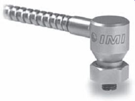
FIG. 4.6: Armor cabling.
8. Intrinsically Safe / Explosion Proof -- Many sensor models are approved for use in hazardous areas when used with a properly installed intrinsic safety (I.S.) barrier or enclosure. Approval authorities include Canadian Standards Association, CENELEC, Factory Mutual, and Mine Safety Administration.
9. Mounting Considerations -- There are several methods for securing vibration sensors to machinery. These include stud mounting, adhesive mounting, and magnetic mounting. Additionally, the use of a probe tip may be useful for very inaccessible measurement points, for locations where physical attachment of a sensor is just not practical, or for determining installation locations where vibration is most prevalent.
Each mounting method will affect the frequency response attainable by the vibration sensor since the mounted resonant frequency of the sensor/hardware assembly will be dependent upon its mass and stiffness. The following diagram depicts how resonant frequency is affected by each mounting technique.
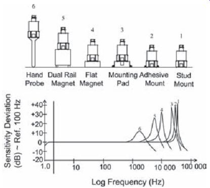
FIG. 4.7: Effect of mounting technique on frequency response.
Stud mounting is the best technique to use to achieve the maximum frequency range. All sensor specifications and calibration information supplied with the sensor are based upon stud mounting during qualification tests. For best results, a smooth, flat surface should be prepared on the machinery surface as well as a perpendicular tapped hole of proper dimension. Spot face tools are available to simplify surface preparation. A thin layer of silicone grease or other lubricant should be applied to the surface and the sensor should be installed with the recommended mounting torque. Be sure to follow all installation recommendations including torque specifications sup plied with each specific sensor model.
If drilling and tapping mounting holes into machinery structures is not practical, adhesive mounting is the next best technique. Sensors may be secured directly to the machine with adhesive or to a mounting pad with suitable tapped hole.
Mounting pads can be adhesively bonded or welded to machinery surfaces at specific vibration sensor installation points. The pads ensure that periodic measurements are always taken from the exact same location, lending to more accurate and repeatable measurement data. Pads with tapped holes are for use with stud mounted sensors, whereas the untapped pads are intended for use with magnetically mounted sensors.
For permanent installations, the pads facilitate mounting of sensors without actually machining the surface onto which they are to be installed. Also, the untapped pads may be utilized to achieve magnetic attraction on non-ferrous surfaces.
Magnetic mounting offers the most convenient method of temporary sensor installation for route-based measurements and data collection. Magnetic mounting bases consist of rare-earth magnet elements to achieve high attraction forces to the test structure. This aids in high-frequency transmissibility and assures attraction for large heavy sensors and conditions of high vibration.
Rail mount styles are utilized for curved surfaces, such as motor housings and pipes. Knurled housings aid in gripping for removal. Hex-shaped magnetic bases are de signed for smaller high-frequency sensors. All magnetic mounting bases should be manufactured from resilient, stainless steel.
Note: Exercise caution when installing magnetically mounted sensors by engaging the edge of the magnet with the structure and carefully rolling the sensor/magnet assembly to an upright position. Never allow the magnet to impact against the structure as this may damage the sensor by creating shock acceleration levels beyond survivable limits.
Trade Magazines:
Intech www.isa.org
Maintenance Technology www.mt-online.com
Reliability Magazine www.reliability-magazine.com
Sensors www.sensorsmag.com
Sound & Vibration www.sandv.com
Turbomachinery International www.turbomachinerymag.com
Vibrations www.vibeinst.org Companies:
GE Bently website www.bently.com
Kaman Instrumentation website www.kamaninstrumentation.com
PCB Piezotronics, Inc. website www.pcb.com
IMI Sensors website www.imi-sensors.com
NEXT: Optical and Radiation Sensors
PREV: