AMAZON multi-meters discounts AMAZON oscilloscope discounts
Because temperature can have such a significant effect on materials and processes at the molecular level, it is the most widely sensed of all variables. Temperature is defined as a specific degree of hotness or coldness as referenced to a specific scale. It can also be defined as the amount of heat energy in an object or system. Heat energy is directly related to molecular energy (vibration, friction and oscillation of particles within a molecule): the higher the heat energy, the greater the molecular energy.
Temperature sensors detect a change in a physical parameter such as resistance or output voltage that corresponds to a temperature change. There are two basic types of temperature sensing:
¦ Contact temperature sensing requires the sensor to be in direct physical contact with the media or object being sensed. It can be used to monitor the temperature of solids, liquids or gases over an extremely wide temperature range.
¦ Non-contact measurement interprets the radiant energy of a heat source in the form of energy emitted in the infrared portion of the electromagnetic spectrum. This method can be used to monitor non-reflective solids and liquids but is not effective with gases due to their natural transparency.
1. Sensor Types and Technologies
Temperature sensors comprise three families: electro-mechanical, electronic, and resistive. The following sections discuss how each sensor type is constructed and used to measure temperature and humidity.
Electro-mechanical
Bi-metal thermostats are exactly what the name implies: two different metals bonded together under heat and pressure to form a single strip of material. By employing the different expansion rates of the two materials, thermal energy can be converted into electro-mechanical motion.
There are two basic bi-metal thermostat technologies: snap-action and creeper. The snap-action device uses a formed bi-metal disc to provide a near instantaneous change of state (open to close and close to open). The creeper style uses a bi-metal strip to slowly open and close the contacts. The opening speed is determined by the bi-metal selected and the rate of temperature change of the application.
Bi-metal thermostats are also available in adjustable versions. By turning a screw, a change in internal geometry takes place that changes the temperature setpoint.
Bulb and capillary thermostats make use of the capillary action of expanding or contracting fluid to make or break a set of electrical contacts. The fluid is encapsulated in a reservoir tube that can be located 150mm to 2000mm from the switch.
This allows for slightly higher operating temperatures than most electro-mechanical devices. Due to the technology involved, the switching action of these devices is slow in comparison to snap-action devices.
Electronic Silicon sensors make use of the bulk electrical resistance properties of semiconductor materials, rather than the junction of two differently doped areas. Especially at low temperatures, silicon sensors provide a nearly linear increase in resistance versus temperature or a positive temperature coefficient (PTC). IC-type devices can provide a direct, digital temperature reading, so there's no need for an A/D converter.
Infrared (IR) pyrometry. All objects emit infrared energy provided their temperature is above absolute zero (0 Kelvin). There is a direct correlation between the infrared energy an object emits and its temperature.
IR sensors measure the infrared energy emitted from an object in the 4-20 micron wavelength and convert the reading to a voltage. Typical IR technology uses a lens to concentrate radiated energy onto a thermopile. The resulting voltage output is amplified and conditioned to provide a temperature reading.
Factors that affect the accuracy of IR sensing are the reflectivity (the measure of a material's ability to reflect infrared energy), transmissivity (the measure of a material's ability to transmit or pass infrared energy), and emissivity (the ratio of the energy radiated by an object to the energy radiated by a perfect radiator of the surface being measured).
An object that has an emissivity of 0.0 is a perfect reflector, while an object with an emissivity of 1.0 emits (or absorbs) 100% of the infrared energy applied to it. (An emissivity of 1.0 is called a "blackbody" and does not exist in the real world.)
Thermocouples are formed when two electrical conductors of dissimilar metals or alloys are joined at one end of a circuit. Thermocouples do not have sensing elements, so they are less limited than resistive temperature devices (RTDs) in terms of materials used and can handle much higher temperatures. Typically, they are built around bare conductors and insulated by ceramic powder or formed ceramic.
All thermocouples have what are referred to as a "hot" (or measurement) junction and a "cold" (or reference) junction. One end of the conductor (the measurement junction) is exposed to the process temperature, while the other end is maintained at a known reference temperature. (See FIG. 1.1.) The cold junction can be either a reference junction that is maintained at 0°C (32°F) or at the electronically compensated meter interface.
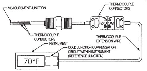
FIG. 1.1: Thermocoupler.
When the ends are subjected to different temperatures, a current will flow in the wires proportional to their temperature difference. Temperature at the measurement junction is determined by knowing the type of thermocouple used, the magnitude of the millivolt potential, and the temperature of the reference junction.
Thermocouples are classified by calibration type due to their differing voltage or EMF (electromotive force) vs. temperature response. The millivolt potential is a function of the material composition and conductor metallurgical structure. Instead of being as signed a value at a specific temperature, thermocouples are given standard or special limits of error covering a range of temperature.
Resistive Devices
Thermistors (or thermally sensitive resistors) are devices that change their electrical resistance in relation to their temperature. They typically consist of a combination of two or three metal oxides that are sintered in a ceramic base material and have lead wires soldered to a semiconductor wafer or chip, which are covered with epoxy or glass.
Thermistors are available in two different types: positive temperature coefficient (PTC) and negative temperature coefficient (NTC). PTC devices exhibit a positive change or increase in resistance as temperature rises, while NTC devices exhibit a negative change or decrease in resistance when temperature increases. The change in resistance of NTC devices is typically quite large, providing a high degree of sensitivity. They also have the advantage of being available in extremely small configurations for extremely rapid thermal response.
In addition to metal oxide technology, PTC devices can also be produced using conductive polymers. These devices make use of a phase change in the material to provide a rapid increase in electrical resistance. This allows for their use in protection against excessive electrical current as well as excessive temperature.
Like RTDs, thermistors' resistance value is specified with a plus-or-minus tolerance at a particular temperature. Thermistors are usually specified at 25°C.
Thermistors' resistance can be made virtually linear using support circuitry such as a Wheatstone bridge. The resistance can then be interpreted using look-up tables to perform a switching function or to drive a meter. They can also be used in liquid level sensing applications.
RTDs (resistive temperature devices), like thermistors, employ a change in electrical resistance to measure or control temperature. RTDs consist of a sensing element, connection wires between the element and measurement instrument, and a support for positioning the element in the process.
The metal sensing element is an electrical resistor that changes resistance with temperature. The element usually contains a coil of wire or conductive film with conductors etched or cut into it. It is usually housed in ceramic and sealed with ceramic cement or glass. (See FIG. 1.2.) The sensing element should be positioned where it can reach process temperature quickly. Wire wound devices should be adequately secured in high vibration and shock applications. Extension wires between the element and instrument allow resistance to be measured from great distances.
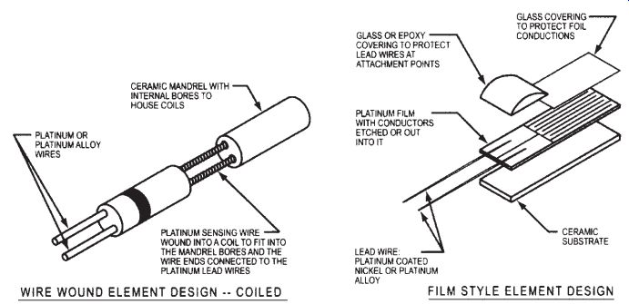
FIG. 1.2: Sensing element designs.
Flexible wire wound and etched foil RTDs are available in various standard configurations. Typically a Kapton®, silicone rubber, Mylar or clear polyester dielectric material is used for electrical insulation. They can be mounted on curved or irregular surfaces using pressure sensitive adhesives, thermally conductive glues, silicone tape, or mechanical clamps. This type of configuration is far superior for monitoring a large area such as the outside diameter of a pipe or tank. They can also be integrated into a flexible heater circuit for optimum control.
2. Selecting and Specifying Temperature Sensors
The following sections address what differentiates each sensor from one another, including temperature, accuracy, and interchangeability. The advantages and disadvantages of each sensor type are also identified.
Selecting Temperature Sensors--General Considerations
How to select the best temperature sensor? In general, all sensor types are useful temperature measurement options, but each has its advantages and disadvantages. For example:
¦ Thermistors provide high resolution, have the widest range of applications, are the most sensitive, and are low cost, but are nonlinear and have limited temperature range.
¦ Thermocouples have the highest temperature region and are durable for high vibration and high-shock applications, but require special extension wire.
¦ RTDs are nearly linear and are highly accurate and stable, but they are large and expensive.
¦ Silicon types are low cost and nearly linear, but have a limited temperature range.
An important consideration in selecting thermal sensors are the materials used, which have temperature limitations. Tolerance, accuracy, and interchangeability are also important. Tolerance is a specific requirement, usually plus or minus a particular temperature. Accuracy is the sensor's ability to measure the temperature's true value over a temperature range.
Regardless of the sensor technology selected, user safety should be the primary concern. Never select a device solely because it has the lowest cost. Choose the device that offers the best performance for its price and always adhere to the manufacturer's guidelines and recommendations.
Each temperature sensing application can present its own unique set of requirements and problems and needs to be evaluated on an individual basis. Here are some questions to consider.
Does the application require contact or non-contact sensing? If the application is moving or if physical contact is not practical due to contamination or hazardous material issues, infrared is the technology of choice.
What temperature range is the sensor required to control or monitor? Thermocouples have the broadest temperature range, -200°C to 2315°C. (Some devices within this range do not have ANSI calibration types established.) Depending on design and material, thermsistors have a usable range of -100 to 500°C. Bi-metal thermostats can handle temperatures from -85 to 371°C.
For cryogenic temperatures, RTDs and some silicon-based devices are capable of approaching absolute zero (0K). Maximum temperatures range from 150°C to 200°C. Support circuitry must be thermally isolated from the sensor so as not to exceed its capabilities.
For non-contact (infrared) devices, temperatures below -18°C or above 538°C would require a custom unit.
With all of these devices, it is possible to exceed these ranges through the use of thermo-wells or by placing the device in a location relative to the heat source. However, this type of approach can affect the accuracy and response of the system.
What is the rate of temperature change of the application? For applications where the rate of temperature change is rapid (>1.0°C/minute), the mass of the sensor may become an issue. The thermal inertia of the sensor is based on its mass. For extremely rapid changes, sensor mass should be kept to a minimum to allow it to more accurately track the change of the application. This includes the mass and thermal conductivity of the thermowell or other protective material.
For applications where the sensor will be remotely located due to environmental or other issues, design verification testing should be performed. This involves using two or more sensors to monitor the temperature of the application, while another sensor monitors the temperature at the proposed sensor location. In this way, sensor location can be optimized.
How tightly do you need to control or monitor the temperature? For certain medical applications or processes involving chemical reactions, tolerances of ±0.1°C or less may be required. For any application requiring tolerances of less than ±1.7°C, an electronic system will be required. Silicon, RTD, thermocouple or thermistor-based systems can all be designed to maintain these extremely tight tolerances. Typically RTDs will provide the greatest overall accuracy.
Remember, in control applications, component accuracy and system accuracy may be totally different. If your system accuracy is no better than + 3°C, it does not make sense to buy the most expensive sensor. You may be able to use a bi-metal thermostat and achieve the same system accuracy at a significantly lower total cost.
Are agency approvals such as UL, CSA, FDA, etc. required at the system or component level? When agency approvals are required, component selection is essentially limited to electro-mechanical devices. Application electrical loads must be reviewed with the manufacturer for conformance to agency requirements. When loads do not conform, it is still possible to have the component reviewed for approval in the specific application.
In some medical and other applications, electronic-based control systems may be not acceptable without the use of a snap-action thermostat as a safety device. Since the failure mode of the electronic system cannot be guaranteed, the thermostat is designed to open the circuit and prevent an over-temperature condition.
How important is total system cost in the selection of the sensor? In high-end applications costing thousands of dollars, the cost of the temperature sensor is typically insignificant. For this reason, the selection is based on required system accuracy. If an accuracy of ±3°C is acceptable, a low cost electro-mechanical device or thermistor-based circuit may be more than sufficient. An accuracy of ±0.1°C will require a more sophisticated (and expensive) alternative.
When dealing with low-cost items like consumer goods (drip coffee makers, popcorn poppers, etc.), the sensor can become a much larger percentage of the total cost. In these applications, the accuracy of the sensor becomes much less important and cost and reliability become more significant. In high volumes, a commercial grade thermostat can do the job reliably for less than $0.50 total cost. With the cost of assembly, circuit board, components, wave soldering, etc., the total cost of a thermocouple or thermistor-based circuit may be higher, but the reliability may actually be lower due to the additional number of components and solder joints.
In the end, the ultimate question is, how much accuracy do you need and how much can you afford to pay? You also need to consider the environmental conditions in which the sensor will be used and what must be done to ensure its survival.
Selecting Electro-mechanical Sensors
Device selection is of extreme importance when using electro-mechanical devices.
In high moisture or corrosive environments, the use of a hermetically sealed device should be strongly considered. Non-hermetic devices may be used for these types of applications based on the manufacturer's input. However, they should be sealed with epoxy or some type of overmold.
For high vibration or shock applications, the design of the device is critical. Typical commercial grade thermostats rely on only armature spring pressure to maintain contact closure. This can cause chattering under high vibration levels and premature contact failure. Consult with the manufacturer during the design phase of this type of application.
Devices that will be subjected to temperatures below -17.8°C (0°F) should employ an inert dry gas internally to minimize moisture condensation or icing on the contact surface.
Application electrical loads should strictly adhere to the manufacturer's advertised limits. Using a device above rated limits can lead to premature failure of the device and the application.
Device selection should be based on environmental exposure temperature, not operating temperatures. A device may be required to operate in a range that conforms to its material capabilities, but be in close proximity to significantly higher temperatures.
Over time, this will lead to deterioration of the device.
Bi-metal thermostats have been used for over fifty years in applications as varied as drip coffee makers and the Space Shuttle. While they can be used as a low-cost control solution for the appliance market, they can also provide a highly reliable device for long-term use in military and spaceflight applications.
Devices are available in either open or close on temperature rise variants. Depending on the type of device selected, setpoints can range from -85 to +371°C (-120 to +700°F). Some devices employ an internal heater to provide protection against both excessive temperature and current.
Bi-metal devices are available in many different sizes, configurations, and capabilities. Since they usually carry the actual application load, they do not require any additional circuitry to perform their function. Current carrying capacities range from dry circuit loads to as high as 25 Amps. Standard production accuracies are available to ±1.7°C (±3°F).
Thermostats are typically rated in life cycles at a specific electrical load and can vary significantly depending on whether they are used in a control or monitoring application.
Advantages
¦ Direct interface with application for fast response
¦ No additional circuitry/components required
¦ Available in both hermetic and non-hermetically sealed designs
¦ High current carrying capacity
¦ Wide operating temperature range
¦ Application/market-based pricing
¦ NASA qualified high reliability and military versions available
Disadvantages
¦ Less accurate than most electronic-based systems
¦ Larger size than electronic-based systems
¦ Creepage-type device cannot interface with electronic components
¦ Can fail "closed" at end of life
Bulb and capillary thermostats are available in single pole, single throw (SPST), single pole, double throw (SPDT) and adjustable setpoint designs in a temperature range of -35 to +400°C (-31 to 752°F). They are also available in manual re-set de signs.
Due to the high electrical loads associated with the typical end applications and their relatively slow switching action, extremely hard contact materials are used. This results in a high initial contact resistance that precludes their use in low current applications.
Advantages
¦ Control can be located at a significant distance from application being sensed
¦ Built-in overtemperature systems available
¦ Broad operating temperature range
¦ High current carrying capability
Disadvantages
¦ Large size
¦ Relatively expensive
¦ Limited number of potential applications
¦ User programmable
Selecting Electronic Sensors
Silicon sensors are available in a wide variety of designs, outputs, and costs. Temperature ranges are available from the cryogenic (1.4K) to 200°C. With high sensitivity and a nearly linear resistance curve, they are ideal for many applications.
IC versions are available with on-chip signal conditioning for direct voltage or cur rent output to controllers or meters. Because they have memory, IC-types can be very accurately calibrated. They work effectively in multi-sensor environments such as communications networks.
The output value of most IC sensors is proportional with temperature over a specific range. Standard accuracy is usually assigned, but can often be calibrated at a specific temperature. Along with basic temperature control and indication, various tempera ture compensation functions are often directly incorporated in printed circuits.
Depending on the application, silicon sensors can be designed as an element into probe assemblies or incorporated directly onto printed circuit boards in a surface-mount configuration. Care must be taken in the design of circuits employing silicon-based technology as excess current can cause self-heating of the sensing element. This can significantly reduce system accuracy.
Some manufacturers have developed IC designs that can be used in place of thermo stats in some applications. They feature factory programmed or user programmable setpoints or hysteresis. They are available in standard Joint Electron Device Engineering Council (JEDEC) configurations.
The operating parameters of the user programmable types are set either through the use of external resistors or are digitally programmed through a two-wire interface with a processor.
Advantages
¦ Less expensive than RTDs
¦ More linear than thermistors
¦ Easier to use than RTDs or thermocouples due to higher output
¦ IC types feature on-chip signal conditioning
¦ Many IC types include communication protocols with bus-type data acquisition systems
Disadvantages
¦ Not as linear as RTDs
¦ Less accurate than other electronic-based systems
¦ More expensive than thermistors or thermocouples
¦ Limited temperature range
¦ Slower thermal response than other electronic-based systems
¦ Typically larger than RTDs and thermistors
¦ Require larger package sizes for immersion
¦ Additional components/circuitry required to control application loads
Infrared (IR) pyrometry. Most IR devices are portable, battery powered, hand-held units that provide a digital read-out of the application temperature. They are also available as fixed-mount devices that can be used with fiber-optic cables for remote sensing. Outputs can be used to drive a display or control loop.
It is important to use a device with the correct field of view for the application to be measured. To ensure an accurate reading, the object being measured must completely
fill the field of view of the measurement system. The measurement system will determine the average temperature of all devices within the field of view including the background.
Several factors can have an impact on both device and system performance. Dust in the atmosphere between the sensor and the target will absorb or deflect some the radiated energy and cause large variations in measurements. Fiber-optic cables may be used to reduce the distance between the sensor and target to minimize error, but the environmental temperature capabilities of the cable itself must now be considered.
Advantages
¦ Allows for non-contact measurement of moving objects or hazardous materials
¦ Can be used in conjunction with fiber optics for remote sensing
¦ Typical temperature range -18 to +538°C (0 to 1000°F)
¦ Accuracy to ±1%
Disadvantages
¦ Accuracy can be affected by surface finish
¦ Field of view must be matched to target size
¦ Ambient temperature can affect readings
¦ Wavelength filter must be matched to the application
¦ Higher cost ($200+) can be even higher if control circuitry is required
¦ Calibration can be difficult and costly
¦ Additional components/circuitry required to control application loads
¦ Dust, gas, or other vapors in the environment can effect the accuracy of the system
Thermocouples have the widest temperature range of all sensor technologies, -200 to +2315°C (-328 to +4200°F), and can be used in a wide variety of environments. (See Table 2.1.) Their inherently simple design allows them to withstand high levels of mechanical shock and vibration. Their small size provides nearly immediate response to small temperature changes.
============

Table 2.1: Thermocouple application information.
Application Information E Recommended for continuously oxidizing or inert atmospheres.
Sub-zero limits of error not established. Highest thermoelectric output of the common thermocouple types.
J Suitable for vacuum, reducing or inert atmospheres, oxidizing atmospheres with reduced life. Iron oxidizes rapidly above 1000°F (538°C), so only heavy-gauge wire is recommended for high temperature. Bare elements should not be exposed to sulfurous atmospheres above 1000°F (538°C). K Recommended for continuous oxidizing or neutral atmospheres. Mostly used above 1000°F (538°C). Subject to failure if exposed to sulfur. Preferential oxidation of chromium in positive leg at certain low oxygen concentrations causes "green rot" and large negative calibration drifts most serious in the 1500°F-1900°F (816°C-1038°C) range. Ventilation or inert sealing of the protection tube can prevent this.
N Can be used in applications where Type K elements have shorter life and stability problems due to oxidation and the development of "green rot." T Usable in oxidizing, reducing, or inert atmospheres as well as vacuum. Not subject to corrosion in moist atmospheres. Limits of error published for sub-zero temperature ranges.
R & S Recommended for high temperature. Must be protected in a nonmetallic tube and ceramic insulators. Continued high-temperature use causes grain growth that can lead to mechanical failure. Negative calibration drift caused by rhodium diffusion to the pure leg of platinum as well as from rhodium volatilization. Type R is used in industry and Type S in the laboratory.
B Same as R & S but has a lower output. Also has a higher maximum temperature and is less susceptible to grain growth.
========
Disadvantages
¦ Must be protected from corrosive environments
¦ Smaller gage wire sizes are less stable and have a shorter operating life
¦ Use of plated-copper instrumentation wire results in errors when ambient temperatures change
¦ Special extension wires are required
¦ Reference junction compensation is required
¦ Less stable than RTDs in moderate or high temperatures
¦ Should be tested to verify performance under controlled conditions for critical applications
¦ Additional components/circuitry required to control application loads
Selecting Resistive Sensors
Thermistors' construction makes them by far the most sensitive of any sensors to temperature changes. Because they do not contain materials such as platinum, they are relatively inexpensive in comparison to wire wound RTDs. Their small size lends them to a variety of applications. Plus, they can be easily molded into protective pack ages for durability.
However, because of the materials used, their operating temperature range (-100°C to 300°C) is narrower than RTDs or thermocouples. And because their resistance vs. temperature characteristics are nonlinear, they are typically used to measure narrow temperature ranges to minimize nonlinearity. PTC-type thermistors have a much smaller useful temperature range than NTC types.
Another drawback associated with thermistors is that they can fail in a "closed" mode.
This could potentially produce a resistance that is interpreted by the system as a temperature reading and not as a component failure.
As with RTDs, thermistors are powered devices. They require electrical input to function. In applications where the power budget is critical or an IC interface is required, a battery back-up might be required.
It may also be necessary to take into account the mass and self-heating of the device in the application. Since these are resistance devices, they generate their own heat in addition to the heat they are measuring. As the temperature of the application in creases, the resistance of the device decreases, increasing the self-heating effect. If the mass and thermal conductivity are sufficient, this effect will be negligible. However, based on the system accuracy required, it should be considered.
Thermistors do not have standard resistance vs. temperature characteristics, so inter changeability can pose a problem. This can require costly system re-design when a change in manufacturer is contemplated. Most manufacturers have their own proprietary resistance curves, usually published as ratios based on a resistance of 25°C. Thermistors can be either very robust or extremely fragile. Bead thermistors typically have extremely thin wire leads that must be adequately secured in high vibration or shock environments. The bead itself must also be rigidly attached to the application in these environments.
High temperature exposure can have an effect on the long-term stability of the sensor. Some ceramic materials, particularly those chosen for lower impedance values, exhibit a tendency to vary from the initial resistance curve.
In critical applications, the manufacturer should be consulted during the design phase to ensure selection of the correct device. In corrosive environments, epoxy-coated beads can degrade in a relatively short period of time. For these types of applications, a glass encapsulated device or probe assembly should be used even though the cost is slightly higher.
Advantages
¦ Low component cost
¦ Fast thermal response
¦ Large change in resistance vs. temperature for more resolution
¦ Extremely small size means faster reaction to change in temperature and ability to use in variety of assemblies
¦ Linearized resistance types available
¦ High resistance values so no lead wire compensation necessary
Disadvantages
¦ Limited temperature range
¦ Lower temperature exposures than RTDs or thermocouples
¦ No established resistance standards
¦ Self heating can affect accuracy
¦ Non-linear resistance change requires additional components for accurate interpretation
¦ Increased component count decreases system reliability
¦ Additional components/circuitry required to control application loads
RTDs are used for a variety of consumer applications including automotive, thermo stats, small appliances, ovens, refrigerators, air conditioners, furnaces, and instant water heaters. They are also popular in industry applications such as process control, electronic circuits and assemblies, printers, laptops, computers, power supplies, battery packs, motor and bearing temperature, HVAC, instruments, and environmental chambers. Medical applications include respiratory, culture, incubator, and disposables. RTDs are very stable over time, and due to the simplicity of their design, are not typically affected by environmental conditions.
RTDs are typically manufactured from materials having a positive temperature coefficient (a usable resistance vs. temperature change). The most common materials are copper, nickel, nickel/iron alloy, tungsten, and platinum.
However, platinum can be exposed to temperatures up to 1200°F and is recognized as the most accurate, stable, and predictable as a resistor. Its useful temperature range is also higher than nickel, copper or nickel/iron alloy. (See Table 2.2.) Plus, it pro vides the most linear resistance change, allowing for the easiest interpretation.
Table 2.2: Sensing element materials and temperature limits.
Because of the low natural electrical resistance of platinum, it is necessary to wind a long, thin wire around a ceramic core to achieve a 100 ohm resistance. This is a standard value for the type of RTD. Lower values are available, but they make signal interpretation more difficult.
Other materials such as copper are used in the manufacture of low cost RTDs.
Copper's change in resistance is actually more linear than platinum. However, its temperature range is more limited and it is susceptible to corrosion, which platinum is not. Copper and nickel/iron alloy devices can be adversely affected by corrosive or high moisture environments and should be isolated from these types of conditions.
The wires that connect the sensing element to the measuring instrument are usually made of nickel, nickel alloys, tinned copper, sliver-plated copper, or nickel-plated copper, and are insulated with PVC, FEP Teflon®, TFE Teflon®, and fiberglass. The materials selected also influence the temperatures in which the RTD can be used.
Manufacturers usually offer a low-temperature and high-temperature construction.
Low-temperature configurations have a range of 400°F to 500°F, and are comprised of Teflon®-insulated nickel or silver-plated copper wires with an epoxy seal. High temperature configurations have a range of 900°F to 1200°F and use fiberglass-insulated, nickel-plated copper wire with a ceramic cement.
RTDs can be mounted with various materials. Most commonly, the sensing element and wires are inserted into a closed-end stainless steel tube, which is packed with vibration damping or heat transfer material such as ceramic powder.
The sensing element in the RTD is manufactured to a specific electrical resistance at a specific temperature. Resistance curves for RTDs have been standardized by various agencies, making RTDs easily interchangeable among manufacturers.
When integrating RTDs into circuits, the resistance of the interconnections must be taken into account. For every increase of 0.33 ohm caused by lead wires, etc., a 1°C error will be introduced.
It may also be necessary to take into account the mass and self-heating of the device in the application. Since these are resistance devices, they generate their own heat in addition to the heat they are measuring. As the temperature of the application in creases, the resistance of the device decreases, increasing the self-heating effect. If the mass and thermal conductivity are sufficient, this effect will be negligible. However, based on the system accuracy required, it should be considered.
Advantages
¦ Very accurate and repeatable
¦ Wide temperature range -200 to +650°C (-328 to +1202°F) depending on type
¦ Extremely stable over time: >0.1°C/year drift
¦ Larger voltage output than thermocouples
¦ Excellent resistance linearity
¦ Resistance can be determined in the laboratory and will not vary significantly over time
¦ Area or point sensing
¦ Low variation for better interchangeability
¦ Can use standard instrumentation cable to connect to control equipment
¦ Established industry accepted resistance curves
Disadvantages
¦ Higher cost than thermistors or thermocouples
¦ Self heating of the RTD can affect overall system accuracy
¦ Larger size than thermistors or thermocouples
¦ Not as durable as thermocouples in high-vibration and high-shock environments
3. Applicable Standards
Standards Bodies
American National Standards Institute (ANSI): http://www.ansi.org A private, non-profit organization responsible for administering the U.S. voluntary standardization and conformity assessment system.
American Society of Testing and Materials (ASTM): www.astm.org
One of the largest voluntary standards development organizations in the world.
Develops and publishes voluntary consensus standards for materials, products, systems, and services.
Canadian Standards Association (CSA): www.csa.ca
Not-for-profit membership-based association serving business, industry, government, and consumers in Canada and around the world. Develops standards for enhancing public safety and health, advancing the quality of life, helping to preserve the environment, and facilitating trade.
Instrumentation, Systems, and Automation Society (ISA): isa.org
Helps advance the theory, design, manufacture, and use of sensors, instruments, computers, and systems for measurement and control in a variety of applications.
International Electrotechnical Commission (IEC): www.iec.ch Prepares and publishes international standards for all electrical, electronic, and related technologies.
International Organization for Standardization (ISO): A network of national standards institutes from 146 countries working in partnership with international organizations, governments, industry, business and consumer representatives.
Japanese Standards Association (JSA): Objective is "to educate the public regarding the standardization and unification of industrial standards, and thereby to contribute to the improvement of technology and the enhancement of production efficiency." National Institute of Standards and Technology (NIST): http://www.nist.gov Founded in 1901, NIST is a non-regulatory federal agency within the U.S. Commerce Department's Technology Administration. Its mission is to develop and promote measurement, standards, and technology to enhance productivity, facilitate trade, and improve the quality of life.
Note: All thermistor testing and calibration baths are measured to the "International Temperature Scale of 1990" using instrumentation from Hart Scientific .
Industry Organizations American Society for Quality (ASQ): asq.org/Purpose is to improve workplace and communities by advancing learning, quality improvement, and knowledge exchange. Advises the U.S. Congress, government agencies, state legislatures, and other groups and individuals on quality-related topics.
International Measurement Confederation (IMEKO): Non-governmental federation of 36 member organizations. Promotes inter national interchange of scientific and technical information in the field of measurement and instrumentation and the international cooperation among scientists and engineers from research and industry.
National Conference of Standards Laboratories International (NCSL International): www.ncsli.org
A professional association for individuals involved in all aspects of measurement science.
Underwriter's Laboratories (UL): www.ul.com
An independent, not-for-profit product-safety testing and certification organization.
Applicable Standards and Specifications Electro-mechanical Devices MIL-PRF-24236 Switches, (Bi-metallic and Metallic), General Specification for Issued by: Defense Supply Center (DOD) ANSI Z21.21 Thermostats, gas appliance Issued by: American National Standards Institute UL873 Standard for Temperature Indicating and Regulating Equipment Issued by: Underwriters Laboratory CAN/CSA 22.2 No. 24-1993 Temperature Indicating and Regulating Equipment Issued by: Canadian Standards Association
Thermistors MIL-PRF-23648 Resistor, Thermal (Thermistor) Insulated, General Specification for Issued by: Defense Supply Center (DOD) ANSI/EIA 337 Glass Coated Thermistor Beads and Thermistor Beads in Glass Probes and Glass Rods (NTC) General Specification for Issued by: American National Standards Institute ANSI/EIA 275 Thermistor Definitions and Test Methods Issued by: American National Standards Institute Thermocouples ANSI MC96.1 Thermocouples, General Specification for Issued by: Instrument Society of America MIL-T-24388 Resistive Temperature Devices (RTDs) and Thermocouples for Shipboard Use, General Specification for Issued by: U.S. Naval Sea Systems Command RTDs IEC-751 Resistance Standards for Resistive Temperature Devices (RTDs)
Issued by: International Electrotechnical Commission JIS C 1604 Resistance Standards for Resistive Temperature Devices (RTDs)
Issued by: Japanese Standards Association DIN 43760 Resistance Standards for Nickel Resistive Temperature Devices (RTDs)
Issued by: Deutsches Institut fur Normung BS 1904 Resistance Standards for Resistive Temperature Devices (Same as IEC 751)
Issued by: British Standards Association
SAMA RC21-4-1966 Resistance Standards for Resistive Temperature Devices (RTDs)
Issued by: Scientific Apparatus Makers Association MIL-T-24388 Resistive Temperature Devices (RTDs) and Thermocouples for Shipboard Use, General Specification for Issued by: U.S. Naval Sea Systems Command 20.4 Interfacing and Design Information The most important consideration with any type of sensing technology is sensor location.
In a control application, where the rate of temperature change is fairly slow, the sensor should be located as close to the heat source as possible. In this way, the thermal lag is minimal. The heat source will cycle more frequently; however, it will eliminate potential undershoot or overshoot of the application.
When the rate of temperature change is rapid due to the thermal conductivity of the material or because of frequent changes in the mass being heated, the sensor should be located as close to the material as possible. This will cause the heat source cycle to be longer and increase fluctuations of the workload. With an electronic-based system, these fluctuations can be minimized with a PID controller.
In all circumstances, the distance between the heat source, sensor and mass to be heated should be as short as possible. This will minimize thermal lag, workload temperature fluctuations and power usage.
Bi-metallic and Bulb and Capillary Thermostats
Electro-mechanical sensors are typically the simplest components to interface with their applications. Since they are capable of either opening or closing with increasing temperature, they are capable of interrupting a power circuit to control or shut down a circuit or of closing a circuit to sound an alarm, turn on a fan, etc.
In most circumstances, thermostats are connected to one leg of the power source.
When the application temperature is reached, the device will function to either make or break the circuit.
When the electrical load required by the application exceeds the capabilities of the thermostat, the thermostat can be used in conjunction with a relay, contactor or some other type of power handling component.
Resistance and Accuracy
Sensor accuracy is a function of production tolerance and any additional calibration that the sensor may get. Calibration can improve the accuracy of an RTD by 10 times over production tolerance. The accuracy values in Table 4.1 apply to production tolerance tight trim RTDs with ice point tolerances of R0 ±0.1%. The thin film values in Table 4.2 are for tight trim platinum RTDs. Both thin film and wire-wound tight trim RTDs with 0.00385 alpha values meet IEC 751 Class B.
In qualifying volumes, RTDs can be laser trimmed for tight resistance interchange ability at any temperature between 0°C and 150°C or to an ice point resistance other than 100 ohm or 1000 ohm. Laser trimming also allows matching the resistance of RTDs with different alpha values at a target temperature.

Table 4.1: Accuracy* vs. temperature.
Table 4.2: Platinum RTD resistance vs. temperature.
Table 4.2: Platinum RTD resistance vs. temperature (continued).
Temperature Circuits
Two-wire circuit:
A Wheatstone bridge is the most common approach for measuring an RTD. As RT increases or decreases with temperature, Vout also increases or decreases. Use an op-amp to observe Vout. Lead wire resistance, L1 and L2 directly adds to the RTD leg of the bridge. (See Figure 4.1.)
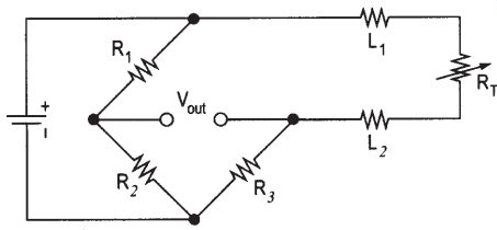
FIG. 4.1: Two-wire temperature circuit.
Three-wire circuit: In this approach, L1 and L3 carry the bridge current. When the bridge is in balance, no current flows through L2, so no L2 lead resistance is observed.
The bridge becomes unbalanced as RT changes. Use an op-amp to observe Vout and prevent current flow in L2. The effects of L1 and L3 cancel when L1 = L3 since they are in separate arms of the bridge. (See FIG. 4.2.)
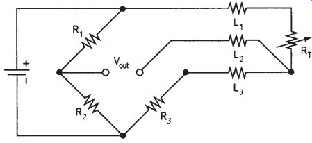
FIG. 4.2: Three-wire temperature circuit.
Four-wire circuit: A four-wire approach uses a constant current source to cancel lead wire effects even when L1 ohm L4. Use an op-amp to observe Vout and prevent current flow in L2 and L3. (See FIG. 4.3.)
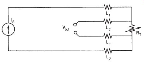
FIG. 4.3: Four-wire temperature circuit.
Temperature switch. The following circuit causes an output voltage to rail whenever the temperature of the RTD rises above a fixed value T1. The open-collector out put simplifies the interfacing of this circuit with additional electronics. (See FIG. 4.4.)
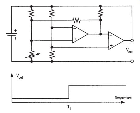
FIG. 4.4: Temperature switch circuit.
Temperature switch with hysteresis. The following circuit uses positive feedback from the output to self heat the RTD enough to develop a hysteresis in the behavior of the switch. Once on, the temperature must drop low enough to offset the self heating before the switch will disable. (See FIG. 4.5.)
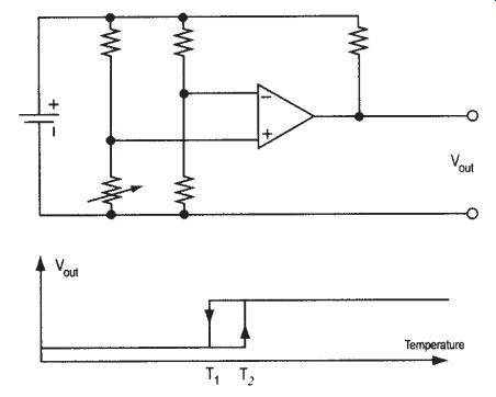
FIG. 4.5: Temperature switch with hysteresis circuit.
Self-heating: Once heat is introduced into the RTD by resistive heating, the equation in FIG. 4.8, which defines thermal conductivity, must be satisfied:

FIG. 4.8: Thermal conductivity equation.
Applying the conductivity equation as a boundary condition on the general solution for the RTD-on-a-surface example, u(x, t) results in the self-heating relationship shown in FIG. 4.9.
Thermal power dissipated the RTD Surface in ee area of the RTD Yielding our result

FIG. 4.9: Self-heating relationship.
Example 1: Applying the result to a low thermal impedance situation, examine an HEL-700 at 0°C, with 0.254 mm (0.010 in) thick alumina substrate (diffusivity k J 38 W/m°C) and 1000 ohm ice point resistance. Here the self-heating error calculated from a 2.3 mA current is negligible, less than 0.02°C.
Example 2: Examining a high thermal impedance situation, use the same RTD, en capsulated in a plastic or epoxy package such as a TO-92. Approximating this as an intervening 1 mm thick layer of polycarbonate with diffusivity of 0.199 W/m°C, the 2.3 mA current now generates a 12.4°C offset.
A plastic encapsulated RTD will exhibit significantly greater temperature offset error than the same un-encapsulated RTD when both are mounted to a surface (or environment) with good thermal conductivity. However, for air measurement, the opposite occurs as in Table 4.3.

Table 4.3: Temperature offset in still air.
Conclusion: When the thermal conductivity of the sensor packaging is lower than the thermal conductivity of the environment being measured, then the sensor packaging can increase self heating. More importantly, lower operating currents always reduce or eliminate self-heating errors.
5. Latest and Future Developments
Sensor manufacturers are currently working on temperature sensors that can with stand higher and higher temperatures for longer periods of time. For example, Honeywell is working with a turbo charger manufacturer to develop both RTDs and thermistors to meet application temperatures as high as 1100°C. Increasing demand for more fuel-efficient vehicles is driving this development. With the implementation of EURO 4 emission standard in 2005 as well as LEV standard in the US, engine manufacturers are trying to squeeze more and more power out of smaller and smaller engines. The current direction is toward the increased use of turbo chargers combined with smaller engine size. High-temperature sensors allow the control systems to monitor gas consumption engine performance and overheating of the turbo charger.
References and Resources
Bakker, A. "CMOS Smart Temperature Sensors: An Overview." Proceedings of IEEE Sensors 2002. Piscataway, NJ: IEEE, 2002.
Bakker, A. and Jonah H. Huijsing. High Accuracy CMOS Smart Temperature Sensors. Boston: Kluwer Academic Publishers, 2000.
Desmarais, Ron and Jim Breuer. "How to Select and Use the Right Temperature Sensor." Sensors 18 (2001):24-36.
Honeywell web site, temperature sensor information: Honeywell web site, thermistor information: Mathews, David. "Choosing and Using a Temperature Sensor." Sensors 17 (2000):54-57.
Measurements Science Conference (MSC): Quelch, D. "Humidity Sensors for Industrial Applications." International Conference on Sensors and Transducers, Vol. 1. Tavistock, UK: Trident Exhibitions, 2001.
Scolio, Jay. "Temperature Sensor: ICs Simplify Designs." Sensors 17 (2000): 48-53.
NEXT: Nanotechnology-Enabled Sensors: Possibilities,
Realities, and Applications
PREV: