LETTERS; EDITORIAL--Aspec; ASK TAA; AUDIO AIDS By Gary Galo; SHOWCASE By Stephen Nitikman; JUST LOOKING
Intro
Filtering became a paramount issue when the CD entered our audio systems. The complex struggle to keep out-of-band garbage out of the signal is a continuing battle. Fortunately audiophile Paul Marchese deals with filtering profession ally, and he not only shares his views on how your CD filter might be improved, but offers a realization which you can build.
Contributing Editor Reg Williamson goes back to some basic matters in reconsidering the RIAA phonograph curve, with some new tools for making sure yours is correct.
Bill Chater completes his “Mostly MOS Preamp” project this time with assembly and power supply instructions. Ben Poehland's rejuvenation of the venerable SWTPC Tigers concludes.
His methodology is applicable to almost any equipment resurrection you might undertake.
Contributing Editor Gary Galo reviews some high performance opamp hardware to lead off his "Ask TAA" column this time. He also returns to some inter changes on his controversial views concerning current flow.
The interesting logo in the middle of the text is by way of a small announcement of a giant step forward for Audio Amateur Publications. The first issue of Elektor Electronics USA, the newest of ten international editions, will be on doorsteps across the USA and Canada on September 20, 1990. We'll tell you all about it next time.
LETTERS
REISSUES
UPDATE THE RECORDINGS MENTIONED in John Sunier’s “Reissue Projects' review (TAA 4/89) are now available on com pact disc as well as LP and cassette.
LILY GILDING
I HAVE READ with interest William Chater's fine article about the 40W all MOSFET power amp (TAA 2/88, p. 7).
I have several questions.
Since the output stage is the totem pole type, there will be an asymmetry in the ability to source or sink current when driving an inductive load. The up per transistor is a source follower and will act as a voltage source due to local degeneration when the load acts as a cur rent sink. However, if the load acts as a current source, the lower output transistor must rely on the overall feedback loop to make it conduct and act as a cur rent sink. An interesting measurement would be the internal resistance of the output stage as a function of signal polarity. Another one would be harmonic distortion as a function of the inductiveness of the load.
In past issues of the JAES, some Far Eastern hi-fi manufacturers have published articles showing how they maintain a value of Ip in a Class B output transistor that is quiescent during its cutoff half-cycle. They claim this is beneficial in reducing the amount of switching the transistor must do when it is finally called upon to conduct, and thus in decreasing the amount of cross over notch distortion at high frequencies. I wonder if you considered such a scheme or whether it would benefit a MOSFET circuit. How does your distortion waveform behave as a function of frequency? As you know, most audiophiles are fond of gilding the lily. Therefore, I think your power supply board would be more attractive if:
1. you made the 30V and ground traces much fatter-perhaps they could take up all the remaining space on the board.
2. you added extra pads to cut off the area where the 10,000uF caps are mounted, and wired in chassis-mounted capacitors-the high-ripple, low-inductance variety are too large for board mounting.
Most purists would opt for polystyrene capacitors in place of ceramic ones on sonic grounds, even for RF bypass caps. Also, the ferrite beads have hysteresis and might affect the sound. You need a program of maximal replacement of small ceramic caps with polystyrene ones and removal of the greatest number of ferrite beads, which will still provide an adequate stability margin.
VICTOR STAGGS, San Diego, CA 92109
William Chater replies:
You raise several interesting questions about the MOS power amp circuit. One question arose in the development of the circuit: Is there symmetry from a series totem-pole arrangement! In the article, I mention this in connection with the derivation of the gain of each half of this circuit, and show that in fact these circuits are balanced. The distinction is simply one of point of view. We are accustomed to considering circuit gain from a voltage-input basis, for which these two half-circuits do differ. But the drivers are current sources; from a cur rent-input basis, there is a “floating” signal input to each side, developed across the 1k resistors R41 and R42.
The circuit analysis then shows like responses from each side. Even the circuit stray capacitances are roughly equal and can be trimmed to balance if needed.
The output impedance of the circuit is therefore the same for both polarity signals (insofar as the transistor trans conductances balance). A test for output im with a sine wave og show a different loss for positive- than for negative-going swings. In fact, it does not show this, but shows a very slight but balanced drop in both senses when loaded with a test resistor or inductor.
The measured drop is that attributable to an internal resistance of 87m at 1kHz, and 170m at 10kHz.
You are right about the industry's attention to bias controls-there are many patents in the area of crossover distortion, dealing with methods of preventing the complete cutoff of the “non conducting” side of a push-pull Class B stage, and with other methods of con trolling bias current. My approach in this amplifier is one of many such circuit approaches, in this case aimed at a result of servo-ing the bias at the optimum point. The servo might be compatible with some of the other approaches, but probably not all. In the present case, I wanted to see how well I could make a MOSFET pair perform, and the MOSFET natural 3-4V forward bias voltage characteristic led to the need for a “smart” bias control.
Many variations might appeal to the DIY constructor, including some of those you suggest. If the amplifier is offered as a kit by Old Colony, perhaps some of these ideas could be included.
In one case, I modified the circuit's power supply to make use of larger capacitance units and received positive listener feedback. (The Digi-Key 22,000 uF/35V aluminum electrolytic capacitor will just fit the power supply card lay out.) The point about the effect offer rite beads is the subject of an earlier letter (see the letter from Mr. Guest and its reply).
FERRITE BEADS
I WAS VERY IMPRESSED with Chater's all MOSFET power amp (TAA 2/88) but something bothers me about all those ferrite beads. The following is a quote from John Linsley Hood, a renowned British designer: 'Ferrite beads are sometimes advocated as a simple way of cutting out un wanted RF breakthrough. Treat these with care. If no significant current is flowing in the wires around which they are threaded, they will do no harm, but in output stages they can be disastrous.
For example, a single ferrite bead around one LS lead will worsen distortion at 10W and 20kHz from 0.015% to 0.4% !
RICHARD GUEST, Toronto, ONT M6G 1V6 Canada
William Chater replies:
You are quite correct. During the development of my MOSFET amp circuit, I discovered that beads on the output leads increase distortion. This amounted to a rise in harmonic levels from about - 78 to - 60dB, re the output fundamental level, measured at 4W. I used a ferrite of 3B7 material, which saturates at about 2 oersteds, or at about 1A peak in the central wire, according to the manufacturer. This leads to a power output in 82 of about 4W. Correcting this to the 10W mentioned by Hood is a nonlinear process, but would lead to at least 4dB more than the 18dB rise I measured.
Thus, the 28dB rise in your example is not surprising.
This is why I used an air-core inductor instead of beads on the output wiring in my circuit. The DC flow in those leads which do have rf beads is always far below the level of concern-these are all low-level signals.
MOS PREAMP
I FOUND WILLIAM CHATER'S “Mostly MOS Preamp, Part I” (TAA 1/90) both informative and fun. However, an error occurred in the schematics. Many, but not all, of the P-channel MOSFET symbols in the circuit schematics are drawn upside-down, so the source and drain terminals are accidentally reversed. Fortunately the card-stuffing guides seem to be correct.
Specifically, in Fig. 6 (RIAA stage) all four P-MOS devices Q5-8 are drawn in correctly. In all four cases the source (and bulk) terminal should be toward the top of the page. Similarly, the one P-MOSFET in Fig. 7 (post amplifier), Q185, is drawn wrong. Its source should be connected to R190.
Surprisingly, Fig. 13 (line driver) has all 3 PMOS transistors drawn correctly, but the closely related schematic for the tape driver (Fig. 18) has Q207 wrong.
This is baffling since the identical device from the line circuit (Q307) is drawn properly in Fig. 13.
I'd also like to ask a question. The second stage of the RIAA amplifier uses a differential PMOS pair with PMOS cascodes. However, the cascode devices (Q7, 8) are operated at wildly different gate voltages: 0.0 and + 12.5V, respectively. This means the differential pair (Q5, 6) is forced by cascode action to operate at markedly different drain-to source voltages Vp. Therefore Q5 and 6 will dissipate different amounts of DC power and operate at different temperatures. Also, to the extent that the PMOS transistors' Ing/ Vp curves are not flat--i.e., Gpg is not zero (Fig. 12)-then the differential pair is imbalanced. If these effects of the unequalized cascode are in deed detrimental (which may be argu able), what are the advantages of the circuit?
MARK JOHNSON, Sunnyvale, CA 94086
William Chater replies:
I am pleased you have read the article so carefully. This attention is beneficial when a complex circuit design is described. I am afraid I must agree with you concerning the errors. The correct connections in the stuffing diagrams notwithstanding, I would like to have backed them up with correct circuit drawings. The cause of this little confusion is (that's right-blame it on some poor innocent computer) the library of parts drawings that I used with my circuit drafting software had the P-channels all drawn 'upside down." To explain your confusion at my in consistencies; I first noticed these errors in producing Fig. 13, and corrected the drawings in the parts library. I then printed Figs. 13 and 18, but Fig. 6 was
done months earlier and I overlooked the error in that case (and with Q207 as well). I hope builders will not be led in to any errors-follow the stuffer while making cards and pencil in the circuit diagram corrections according to Mr. Johnson's suggestions.
The P-channel second stage of the RIAA amplifier is related to the design I did in the earlier article for the 40W MOS power amplifier (TAA 2 and 3/88).
That circuit called for a similar drive for the output stage. In the preamp I used some of that thinking and split the power dissipation and voltage drops about equally between Q5 and 7.
Transistor Q7 is operated at a drain to-source voltage drop of about 23V, with its drain node at an essentially constant potential where it drives the cur rent mirror Q9 and 10. With the Q8 source set about + 16V, its drain-to source drop is nominally about 12V for small signal conditions. This way, there is less imbalance in the heat loads be tween Q7 and 8.
You can't strike a balance between Q6 and 8 since the circuit must be able to drive Q11 and 12 gates to at least 12V positive, and preferably higher. These balances are not very important, as the heat load on all four of these P-channel transistors ranges from 10 to 40mW in devices rated in air for 0.8W (1W if you use the IRFD9210s).
QS5's drain-to-source drop is about 12V while that of Q6 is about 3V, as you noticed. Figure 12 is not the curve for Q5 or 6 (it is for a P-channel junction FET, the J270) but the curves for the IRFD9210 (or the VP1310) at these currents are similar to Fig. 12. This curve shows a very small change in gate voltage is required to correct for a 9V change in drain voltage (the u factor of such a device is really large). The actual difference between the drains of the in put stage at R03 and R05 is more because of P-channel device gate-to-source inequalities, which are less than 1% of the drop in R03 or R05. The input stage is therefore still well balanced.
The advantage of my voltage settings is just that a little more dynamic range at the output can be achieved: the drain of Q8 can rise to almost + 16V before clipping. As I mentioned in the article, probably the largest signal voltage to be expected in the preamp system is at the output of the RIAA stage if you use a moving-magnet cartridge of large output voltage. It was to enhance this aspect of the design that I made the somewhat asymmetric choice of bias conditions.
I would like to make a comment for anyone building this circuit. I expect if Old Colony makes a kit available the resistors supplied would be 1% tolerance.
This should prevent a pile-up of parts tolerances from leading to a saturated condition in transistor Q6, which as mentioned above runs at only about 3V drain-to-source voltage. You would be wise to make a voltage map of all the card circuits during test, for the record as well as for detecting problems.
If it came about that Q6 for example showed too small a Vp drop, perhaps the easiest change to correct this is a slight reduction of R30. This would lower the voltage at the gate of Q8 and raise the drop across Q6. You might expect a resulting slight reduction in the peak output signal but for the fact that the pile-up of tolerances probably had preset this condition in the opposite direction. I would be interested to hear if any builder has had such experiences with these adjustments.
CAR AMP MOD
THIS LETTER IS IN response to the article "RKV Car Amp” in the 4/88 issue of Audio Amateur. I ordered this in back issue form and have not yet received Part II, so my question relates to some material that I have not examined. How ever, any thoughts on these questions would be appreciated.
As you mentioned in Part I, one of the main concerns regarding car audio components is location, particularly due to space limitations. This becomes more complex when you use multiple components in a multi-channel system. I am interested in building your design but would like to do so in a 4- or possibly 6-channel single chassis. I want to take advantage of using a single power source and ground source to keep installation simple and conserve space. This amp would be mounted in my trunk and would be supplied by a 4-gauge power and ground cable. Is this feasible? I should warn you, although I have read a lot about home and auto sound and have done a few installations, I am by no means an electrical engineer. I am in the process of teaching myself electronics, so if you can refer me to a book, that will be sufficient. Also, is there any harm in painting the aluminum extrusions used as a heatsink? By using zinc chromate primer and a topcoat, will I hinder the heatsink in a significant way? Thank you for your help and for making public the fruits of your labor.
LAWRENCE J. BELCHER, Charlotte, NC 28213
Randolph Vikan replies:
Your letter of inquiry is gratifying. I appreciate your interest and hope the following will answer your questions sufficiently.
The trunk is an excellent location to place big or complex systems. Four gauge power and ground return wires should be fine for any reasonably powered system mounted in the trunk.
The power supply I designed for my amp was meant to operate two channels of audio amplification. I don't believe one power supply board can drive six channels of amplification to acceptable performance levels. The total power out put of most home and car amplifiers is limited by their power supplies (assuming a quality output stage in the amp).
With 82 loads, the amplifier's rail volt ages generally set the power output limits, with 42 or less loads, the sup ply's current capacity is usually the limiting factor. The total output power of my car amplifier is limited by the throughput capacity of the switching supply, approximately 220W.
The two audio amps run at about 70% efficiency at full power, producing 75W per channel into 49. If more channels were operated off the same supply the output power per channel would drop to what I would consider unacceptable levels. A better idea would be to operate each channel with its own dedicated switching power supply board. If you do this with my amps the output rating per channel would be: 60W into 82, 110W into 42 and 140W into 20. Unfortunately this makes for a complex total system. So I decided to operate two channels from one power supply board as a compromise between complexity and performance. I chose to put the power and amplification on separate boards allowing you to make the power distribution decision yourself.
I prefer anodized finish versus paint on heatsinks. Most commercial car amps that cross my bench have had anodized heatsinks. This has led me to assume that the anodized finish is superior thermally. Since it's more expensive to anodize aluminum than paint it, I doubt if a commercial manufacturer would bother if there weren't a performance difference. I have never had much luck getting paint to stick to aluminum.
I've made a change in the parts list for the power supply. Apparently the Mallory capacitors I recommended for C5, 10 and 11 are no longer manufactured.
I now recommend the Sprague 80D #332P0O35KAS instead. With these lower voltage capacitors (3,300uF/35V DC) the turns ratio changes I suggested in TAA 1/89, p. 28, will now be required. That is, secondary turns change from 14 to 11 and tertiary turns change from 4 to 3 (primaries remain the same at 4).
Resistors R16 ( DC-to-DC converter) should be changed to 36k from 39k. The value of R16 and the coupling characteristics of the optocoupler OPTO1 deter mine the secondary rail values. Variability in OPTO1 may make it necessary to tweak R16's value in order to get the + 33V DC secondary rails I now specify.
With these slightly lower rails the value of R16 and 17 in the audio amp (TAA 1/89, p. 21) should be changed from 2.7k %W to 2.4k %W.
Vikan's interesting article, “RKV Car Amp” (TAA 4/88, 1/89).
1. I suggest some inductive decoupling of the power supply to keep switching noise out of the amplifier (hinted at by the note “switcher noise removed” under distortion specifica tions). Such noise can trigger amplifier instabilities, burn up resistor R35, interfere with the car's FM reception, and violate FCC EMC rules.
2. The comment about improving stability by increasing the R25-28 values assumes the cause of instability is gate oscillation. If this is not the case, then you may need to change C4, C5, R11 and R12. It is also a good idea to place a small series resistor in the path of an ...
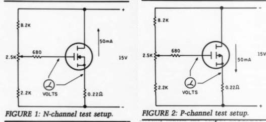
FIGURE 1: N-channel test setup. FIGURE 2: P-channel test setup.
...input filter like C1, otherwise, at some high frequency, it will present a near zero source impedance for Q1 and Q2, causing an unnecessary zero in the transfer function, and possible associated instability.
3. Finally, and most important, while Vikan mentions FET matching for the input transistors, he overlooks it for the outputs. For parallel operation of HEX FETs such as these, matching is imperative. Gate voltages and gain can vary from device to device so much that proper current sharing is unlikely without matching or luck (which can occur if you happen to get devices out of the same wafer). The amp will actually function with just one FET, but under heavier load, overheating and destruction can occur.
REINHARD METZ Wheaton, IL 60187
Randolph K. Vikan replies:
All car amplifiers that use switching power supplies show some traces of high frequency power supply oscillator component at their output terminals. If I measure the harmonic distortion with out inserting a low-pass filter in the measurement path, I get readings of 0.12% at 1W and 0.2% at rated power output (1kHz into 8 ohm, both channels driven). This means the high frequency component at the amp's output was down at least 54dB from full power out put. This level isn't enough to damage any car tweeter or heat up resistor R35.
I have checked the output for RF switching noise and, although present, it's at very low levels and not enough to interfere with my FM tuner.
Inductive decoupling of the supplies would probably reduce this noise even more. You easily could add the inductors in series with the B supply lines be tween the power and amplifier circuit boards. It's been my experience, though, that system grounding and shielding within the amp have a greater effect on the amount of switching noise at the output terminals.
Your comments about improving stability are correct. I've tried adding gate resistors to the input FETs and found they have no effect on the circuit. But if you'd like to make this change, remove the four incoming jumpers (J) near the devices and replace them with 1002 %W resistors (see parts diagram, page 29, TAA 1/89).
To ensure good current sharing in my circuit, match the output MOSFETs.
The most critical parameter to match is the voltage gate to source (Vg) thresh old (Siliconix MOS power Applications, page 5-56). When I built my three stereo amplifiers I grouped the twelve N-channel devices required into roughly matched pairs using the test setup in Fig. 1. The P-channel devices were grouped into matched pairs using the test setup in Fig. 2.
This matching allowed me to avoid the gross mismatches you describe.
Also, I purchased all the MOSFETs with the same date code to improve my chances of obtaining close matches from the start. The date code is usually printed under the device type. For example a code of 8532 indicates the device was manufactured in the thirty second week of 1985. In some cases the eight is assumed and the code would read 532.
If you don't wish to match output devices, add source resistors (e.g. 2202, 2W) between the source of each device and the output line to force current sharing.
RYAN'S REGULATOR
I READ KIT RYAN'S article, “A Power Supply Regulator for the ADCOM GFA 555," in TAA 4/89. I've been toying with high power regulators for my power amp, and a couple of things about your design caught my eye.
A problem that should be mentioned:
I think the R1/R16 resistors in the reference voltage circuit, as well as the R7/R22 pair in the feedback circuit, need to be 1W units, since their normal dissipation is about 0.45W. You didn't mention this in the text (that I could find). Also, the circuit board artwork allows only 0.5" for those resistors--a tight fit. The usual spacing for 1W carbon resistors is 0.65-0.7".
I think you could improve regulator performance with a couple of easy modifications. First, I would get rid of the 12V zener diodes and substitute a good reference like the LM 329. They're avail able for 81 cents each in small quantities from Digi-Key. You could also greatly increase the value of R1/R16 and simultaneously get less dissipation and greater power supply noise rejection. Since the LM329 only requires 1mA, you could change R1 to 56k and R2 to 33 k-ohm.
However, the lower 6.9V terminal volt age of the LM329 would be near the edge of the differential pair's minimum common mode voltage-you'd probably have to string two in series.
You might even try connecting R1 to the output instead of the input to improve your DC accuracy. On bipolar out puts, this sometimes causes the output to lock up in the opposite direction of what you intend, but I doubt this would be a problem with your circuit.
Second, to improve the common mode rejection of your circuit I would substitute a 2mA current source/sink for the R4/R19 resistors. A simple circuit (Fig. 1) would help a lot.
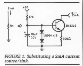
FIGURE 1: Substituting a 2mA current source/sink.
As I mentioned, I've been experimenting with high current/voltage regulators. I've been using op amps, but the boost transistors seem to give me a lot of trouble with oscillation. Your circuit apparently doesn't have that problem, and it does have fewer parts than the one I designed. I guess I'll have to give it a shot and see how it performs.
I might try redesigning the driver stage of the positive regulator to pull the gate of a big P-channel FET down (and the mirror image on the negative one), rather than trying to go above the base of an NPN transistor. You might get lower dropout this way. I'm not sure I'd want to live without current limiting of some kind either. I screw things up too often.
Well, your excellent article certainly gave me some things to think about. I hope you find my suggestions helpful.
THOMAS MOSTELLER, Lansdale, PA 19446
Kit Ryan replies:
You bring up a lot of issues-1I'll try to answer each one briefly.
Regarding the power dissipation for R1/R16 and R7/R22, you are quite right that from 0.37-0.45W must be absorbed.
I don't think I stated the power rating for these resistors, but %W is perfectly adequate. I have been running this size in my amplifier for several months with no problems. One-half watters will fit within the standard 0.5" lead spacing on the board. You can use 1W if you stand them on end but under no circum stances use ordinary carbon composition resistors. Their value drifts with temperature, humidity and age, which will cause continual changes in the regulator output voltage settings since these resistors are in the sensing resistor divider network. The 1W carbon composition resistors are also much noisier than the metal film types which, again, will cause noise to appear on the regulator's output. If you feel you need 1W capacity, try the metal oxide type.
Substituting LM329s for the 12V zener should work well and is a nice touch I simply overlooked. Whether you use one or two, be sure to adjust the R5/R6/R7 divider network to keep the potentiometer in the proper adjustment range.
Substituting a current source for R4/ R19 is elegant but not really necessary.
Since the base of Q1 of the differential pair is at a constant potential (e.g. the 12V reference voltage), the common mode voltage at the emitters of Q1/Q2 is only half the sensing voltage that appears on the base of Q2, a few mV at most. The effect of this common mode voltage on the existing circuit is a very slight decrease in open loop gain of the regulator. As designed, the regulator limits voltage fluctuations to only 20mV at high power levels, which should be quite adequate. Also, the additional components will be almost impossible to add to the narrower board I have pro vided for the newer ADCOM chassis (available from Old Colony, #PCBY-2).
You make a good observation about the difficulties of designing complex cir cuits with op amps. A circuit such as you describe with an op amp and booster transistors within an external negative feedback path is bound to have problems. There would be at least four
"poles” in such a circuit (three in the typical op amp plus one for the booster transistor) causing significant phase shift through the amplifier, and making it extremely hard to stabilize the circuit against oscillation. My circuit has only two poles and can be stabilized with just one capacitor, C3. In high powered circuits like this, I tend to stay away from ICs and opt for simplicity and rugged ness.
Your plan for using big FET transistors is not clear to me so I can't comment.
Remember, the fuses are left in the ADCOM to protect the amplifier.
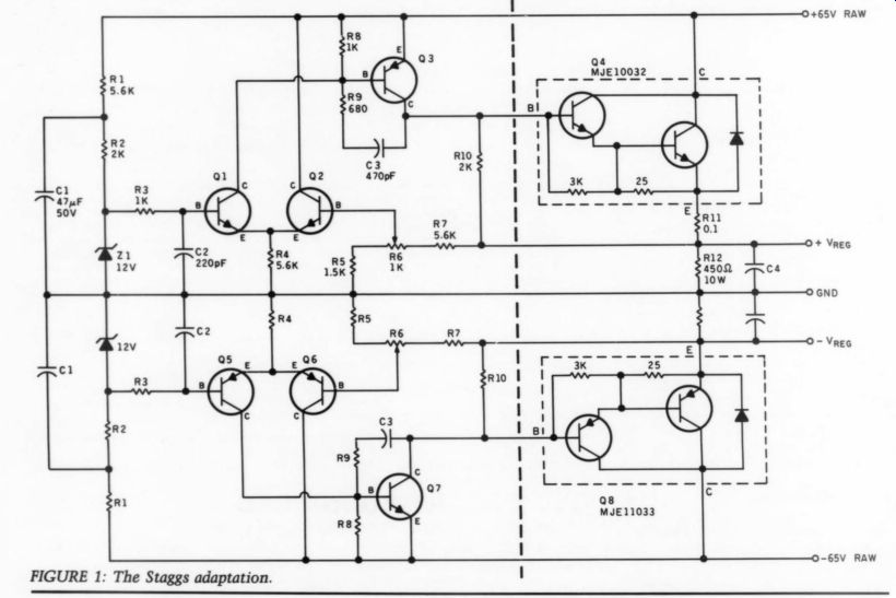
FIGURE 1: The Staggs adaptation.
There are many ways to design circuits such as this one, as you point out.
If you would like to pursue your suggestions, a low risk approach would be to build the circuit '“as is,” then make selective mods and test for performance and audible improvement. I would be delighted to read the results in a future issue of TAA.
RYAN ADAPTATION
I HAVE ADAPTED Kit Ryan's voltage regulator circuit published in TAA 4/89 (Fig. 1). Thanks for a great circuit. My amplifier load is a Hafler DH-220, 220W total, and I set the regulated voltage to 50V. The rest of the electronics is already regulated, so this was a test of regulating only the loudspeaker power.
Yes, the difference is as you have de scribed in the article. Most of the parts were ordered from Active Electronics, who had the Darlingtons as well (I prefer American parts).
The physical realization of the regulator consists of a pair of identical boards with the driver circuits on them, wired to the output Darlingtons with a few inches of wire, and to the amp with 5 runs of #14 Teflon wire, silver tinned.
I mounted each Darlington with silicon gaskets to a large, surplus finned heat sink in the fashion of a power amp. I used star grounding at the raw power supply, and no noise is evident. A small aluminum box houses the electronics and provides sides to which I mounted the heatsinks. Dummy load resistors keep things running at a set minimum current (learned by experiment on IC regulators). [Etched circuit boards, order #PCBY-2, are now available from Old Colony for Ryan's mod.-Ed.] The preamp (DH-110) and amp have been given totally modded capacitors, e.g. no electrolytics passing audio, and otherwise use polystyrene and polypropylene film. All signal wiring is either Teflon insulated coax or silver-tinned copper-no vinyl-insulated wires. The result is astonishing high-frequency reproduction and absence of distortion, the last of which (very small) left with the addition of your regulator. Because of this regulator, the bass notes are more solid and detailed.
The speakers are a sophisticated de sign using Philips drivers-1" dome tweeters, 2" dome midrange and 10" woofer driven by a very accurate cross over, and loaded with tuned ducted ports.
The imaging and depth are wonderful, and they detail exceptionally well. The sensation is one of not hearing the speakers at all, just the music from the space between. Great fun, and again, thanks for the nice regulator circuit and article.
DARCY STAGGS Orange, CA 92669
Kit Ryan replies:
Nice job. As they say, imitation . . . .
Variants of this circuit should help any power amplifier as it did yours. The monster pass transistors you used, 50A @ 300W, ought to be enough for virtually any amp.
Regarding American versus Japanese transistors, I wish there were more of a choice. Sadly, American manufacturers have all but abandoned the consumer electronics market, the DACs (digital to-analog converters) used in CD players are a rare exception. Look at the Time Lord transistor ad in the last issue of Audio Amateur-there are no '"2N” equivalents for most of these complementary pairs. When it comes to high frequency/high power output transistors or the high gain/low noise FETs used in the Borbely preamp, it's Japanese or nothing. A tougher problem for us home brew builders seems to be getting good looking cases at reasonable prices. Most of the suppliers have been lured away to build computer cabinets, leaving us with slim pickings.
[You might have a fresh look at Sescom cases.-Ed.]
SAFET
THE SAFETY ASPECTS of the transformer less supplies discussed in TAA 4/89 (p. 62) may be a little chancy if you were going to build a piece of equipment for some technically innocent person. No problem for the amateur who lives alone and knows what he is doing. The ideal application for these supplies, however, is not in the amplifier realm at all.
Take a look at the stabilized AC power supplies in TAA 4/88, p. 31. This particular version is going to need three transformers, including the power sup ply. That's too many.
Here's a block diagram (Fig. 1) of a possible approach to an optimized AC motor supply. In this case, it doesn't matter at all if the supply is hot, since nothing here connects to any chassis grounds. The bridge amplifier approach is used to avoid having to design an amplifier across 300V + rails. The oscillator and dividers live inside the rectified line environment, powered by a zener/ transistor pre-regulator and a standard 3-terminal regulator. Of course, the 60Hz sine wave would be AC-coupled into the amplifiers. A few volts would be lost in junction drops, but that shouldn't be a problem. If anyone has an appropriate amplifier design, this would be an efficient way of stabilizing a turntable supply.
HILARY PAPROCKI, Rochester, NY 14621
Nicholas Hogya replies:
Of course, I agree with you--experimenting with transformerless supplies is definitely chancy for the technically innocent, but, although I am not ready to say they are “no problem for the amateur,” I would like to encourage more interest in the design of transformerless raw supplies.
The Power Supply Handbook, (Tab Books, 1979, pp. 36-41) gives some interesting indications of possible design techniques and makes me think there is ample scope and challenge for any creative engineers associated with TAA., was interested in Mr. Mortensen's DC300B amplifier design (TAA 1 and 2/89).
I constructed aDC300B amplifier and put it to extensive listening tests in com parison with the above mentioned amps which have been extensively modified.
While the DC300B could not match the clarity and responsiveness of the OTL-4, it did manage to significantly outperform the Moscode 301, proving the justification of Mortensen's input and driver stage design in comparison with the oversimplified designs of commercially available hybrid amplifiers.
However, while I think the DC300B amplifier rates as one of the best hybrid amps I have auditioned, it still exhibits the unacceptable design philosophy fault of all available hybrid designs. That is, the capacitor coupling between driver and output stages, and the enormous and clearly audible coloration caused by this.
No matter how good the design of the tube and MOSFET stages of this type of amplifier, its abilities are constantly restricted by the detrimental coupling capacitors. Although I agree with Mr. Mortensen, that good coupling capacitors will always outperform a simple servo circuit design, I do believe he would be astonished by the abilities of a hybrid amp design, using a well thought out servo circuit allowing the use of bipolar voltage supplies for both tube and MOSFET stages, and as such, DC coupling of tube to MOSFETs.
While such a design has so far eluded all amplifier designers, I have had the pleasure of auditioning an Australian all tube OTL amplifier with the aforementioned characteristics.
Unfortunately, this amplifier is not on the market (for reasons known only to its designer). However, if such a design could be applied to a hybrid amplifier like the DC300B, the performance would outperform the DC300B. I would be most interested to learn whether any de signer can produce a workable design of such an amplifier.
RICHARD LAWRENCE, Victoria, Australia
Hans Mortensen replies:
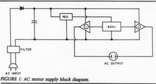
FIGURE 1: AC motor supply block diagram.
Thank you very much for your interest in my DC300B amplifier. Hoping to be but an amateur in the best sense of the word, reactions from professional audio engineers such as yourself are a wonderful experience. The shortest and in fact most appropriate answer to your letter is, I agree-and hope, too, that somebody has solved the problem you mention. But a word of explanation might not be out of place.
I did not think of the DC300B and the OTL-4 as equals. With a friend, I have constructed two sets of OTL-2s-so I am fully aware of the limitations of my design. I may have inadvertently indicated in the article that the DC300B compromise.
[67]
I state in the article that direct coupling Treatment in a stable way. This still holds rid which incorporated direct coupling between the two types of active devices and a servo circuit. I still remember its sound. I had never before or since experienced anything like it. It sounded as if it sculpted the shape, color and sound of every single detail. Somehow it captured the essence of the music. I know what you mean when you say I would be “astonished by the abilities of a hybrid... using a well thought out ...
---------------------
CAVEAT CORRESPONDENTS
Things that go bump in our round file:
1. "I'm thinking of building a 16-in, 8-out console in my basement. What tape recorder should I buy?"
2. "Is my Fisher Z-705 receiver pega were sed 1 aged, Siwkinenod Siig please answer the following nine questions based on my experiences building your inverted RIAA kit."
4. "Please forward this [unstamped letter to Ralph J. whose letter ap peared in one of the 1970 issues- don't remember which."
5. " I have a Milhous 10W integrated stereo amplifier and a Gesundheit turntable. Which of the following six cartridges would you recommend?"
6. Queries with no stamped, self addressed envelope or postal cot pons enclosed. oo
7. Letters without return addresses on them whose envelopes have strayed away somewhere.
8. illegible hand-written letters scrawled on odd scraps of paper. If you have no access to a typewriter, please try to be sure our typesetter doesn't lose his eyesight and his mind in deciphering your writing. (This is especially important if you want us to publish your classified ad.)
----------
... servo.” However, stability was a serious problem, and at that time I didn't have a clue what to do about it. My final conclusion was something like: Life is tragic, once you glimpse paradise it eludes you.
I decided to give in and use AC-coupling between the tubes and the FETs.
I felt defeated but found some comfort in the thought that Julius Futterman himself decided that although servo controlled direct coupling is possible, it is also so expensive, prone to faults and dangerous to the speakers that it isn't worthwhile. I didn't find any comfort in Harvey Rosenberg's statement that capacitor coupling is even better-in an absolute sense-than direct coupling.
That statement is an evasion (Harvey Rosenberg, 'Understanding Tube Electronics," NYAL, NY, 1984, p. 60). 1also looked at other output transformerless designs (the Japanese Taki-circuit, the Luxman MO36, the Croft and others)- they are all alike in that they use capacitor coupling, very elaborate adjustment procedures or both. The design you mention is the first servo-controlled all tube device I have heard of, and of course a closer look at the schematic would be a most welcome experience.
As it happened I couldn't stop thinking of the direct-coupled servo-controlled hybrid, and about a year ago I dug up the old boards. I had an idea, and it seemed to work. I may have the solution to the problem, but I don't understand why it works, and I haven't had the time to test the circuit extensively. But the fact that there is somebody who would appreciate a design of that kind has made me decide that it is worthwhile. When (if) the circuit works, I hope TAA will accept it for publication.
RC4136 REPLACEMENT
RECENTLY, ON TWO separate occasions, | have needed to replace the old workhorse RC4136 op amp. Looking back through past issues of TAA and SB, I found others with the same need. The main problem comes from a nonstandard pinout on these amps. My solution is to make a small configuration circuit board (avail able from Old Colony, #PCBZ-1), to alter the RC4136 pinout to a standard 4-pack op amp pinout. Figure 1 is the art needed to accomplish this. Place your negative so that on the etched copper side the IC labels can be read correctly. At the RC4136 position, install extender pins or a wirewrap socket. At the other position put your new amp-a TL0074 or the ...

FIGURE 1: Artwork for altering the RC4136 pinout.
... much better Analog Devices AD713 come to mind. Then remove the old RC4136 amp from your circuit and drop the extenders into this position.
I hope this circuit artwork will be useful to others. With the improvements in op amps in recent years, upgrading to a better sounding amplifier will provide definite audible changes. Active cross over designs, rumble filters, early guitar effects boxes, and Carver equipment immediately come to mind.
JOHN ALLGAIER Kalamazoo, MI 49004
PSE STUDIO II
I own a PSE Studio II power amp and would like to upgrade. I have called PSE for a parts list and layout of the amp but they did not respond. I have also contacted other companies that do mods but they were not familiar with the amp. Does anyone know how to modify this amp?
Todd YOUNG, Ottumwa, IA 5250
MORE ON DC300B
THERE ARE A FEW errors in the DC protection circuit in Hans Mortensen's “DC 300B Tube MOSFET Amp” (TAA 2/89).
In Fig. 12a, R6 and 7 should be ex changed. R13 should go to the base of T2, not the emitter. In Fig. 9, pins 9 and 10 of the 4001 chip should be exchanged to correspond with the board in Fig. 12.
MIKE SOMERS, Madison, WI 53703 Hans Mortensen replies:
Thank you very much for your interest in my DC300B. I apologize. You have in fact discovered a couple of errors in the article. It is true, R13 should go to the base of T2 in the DC-protection circuit and not to the emitter. However, you should not exchange pins 9 and 10 of the 4001 chip, Fig. 9. Pins 8 and 9 should be exchanged-in the diagram only-the board is correct. As for exchange of R6 and 7 in Fig. 12a, you are right again, but the error is of no consequence.
HEATHKITS –
READING A RECENT TAA issue I saw Heathkits mentioned. I recently put together two power amps, the AA-2500 designed by Harman-Kardon. They are easy, except when it came to the final DC current adjustment. No matter what I did, the current value fluctuated wildly. I spent at least two futile hours going over everything. Tapping various parts of the circuit board indicated the presence of a break in the tracks. Finally I found the fault; a hairline crack barely visible to the eye. Jumpering that section resolved the problem. The second amp had exactly the same problem. I spent an additional two hours verifying this. After all, how many times does lightning strike in the same place? To spare others the aggravation I went through; beware of circuit board hairline cracks.
I would appreciate hearing from any one with suggestions or modifications to improve on the sound of this amp. Keep up the good work.
MICHAEL MAR PO Box 32231 Oakland, CA 94604
[We contacted Heath regarding the problem. They have questioned reader Mar further and also asked their service department to investigate. Other readers with a similar problem are asked to con tact Larry Burghdoff at Heath.-Ed.]
MIRACLE CURE
MAY I ADD MY experiences to Richard Painter's Audio Aid, “A New Use for Sorbothane” (TAA 1/89). First, a warning.
Although Sorbothane is predictably effective when used as a surface treatment (I use Audio-Quest's self-adhesive sheet on difficult surfaces), it can be unpredictable when sandwiched between two
components. It appears to convert vibrational energy to a very low frequency, and if a component is sensitive to this, you may experience an unstable and very disquieting grumbling.
This happened when I was trying to cut down acoustic feedback in my Marantz 873 CD player (a close cousin to the Magnavox family); a Sorbothane sheet between the circuit board and the case had disastrous effects. On the other hand, sticking Sorbothane to the top of the D/A converter, and subsequently to the unpopulated areas of the board around it, certainly increased the resolution. (A couple of British manufacturers are now damping their converter chips.) My significant other, lending her ears and encouragement, suggested damping the 5532s as well; I did this, thinking it could do no harm, without listening separately to the result.
I recently started making Walt Jung's Audio modification, gathering courage for the full POOGE-4 treatment. As expected, I gained by substituting polypropylene output capacitors and bridging the “safety resistors,” but installing AD712s produced mixed results. Certainly there was increased instrumental detail and more sense of acoustic space, but the bass was less incisive and there was an edge to loud strings and brass.
Worst of all was an unmusical, synthetic quality to the sound. After a couple of days I decided I was not enjoying music anymore and resolved to replace my comfortable 5532s. As a last resort I stuck Sorbothane squares to the AD712s, and immediately the musicality was restored with all the extra detail. You could say it had all the sweetness of tubes.
I find this incredible, not because I'm unaware of vibration effect on electronics (and it follows that microelectronics should be even more sensitive), but be cause, to my knowledge, no one has suggested the mechanical damping of op amps. | urge some broad-minded souls to try it, despite their skepticism. Maybe this is why op amps are unpopular among audiophiles, despite their obvious advantages in many circumstances.
DAVID FOXON, Marston, Oxford, OX3 0RZ, UK
Editorial
ASPEC
The Hubble telescope is awaiting a weather change to be launched into orbit outside Earth's atmosphere as I write this. Experts predict we will be able to see light from objects 14 billion light-years from our location in space, which is “only” a billion light-years from the outer edge of our universe, or those artifacts which have travelled farthest from the theoretical 'big bang' center of creation. The $2 billion device is the latest evidence of what our imaginations are capable of. The young scientist who first conceived the idea at Princeton University a generation ago was immediately consoled by his professor on its probable failure.
The telescope embodies a great deal of reliable knowledge, laboriously learned and verified over the decades. Its foundation is a set of performance standards which are the achievement of hundreds of dedicated researchers, but the common heritage of astronomers the world over. Hubble’s large mirror is said to be the best in the world. I doubt seriously whether that is a “subjective” evaluation. Clearly, verifiable, repeatable performance knowledge has made this latest enterprise possible.
Most disciplines these days are actively pursuing new standards of performance. I was impressed recently to read of a new development among computer companies to find agreed-upon performance achievements. A group of editors at Electronic Engineering Times invited a group of participants including Sun Microsystems, Hewlett-Packard, Apollo Computer and MIPS Computer Systems to set agreed-upon standards for computers. These were eventually joined by Digital Equipment, Data General, Control Data and IBM.
With that sort of aggregate, most of the remaining computer manufacturers joined the group, called Systems Performance Evaluation Cooperative, or SPEC.
The new performance standards are not only in place, but are having a visible effect on the participants. (See EET March 12, 1990, p. 28.) Winners who become losers as their products are outperformed are not nitpicking the standards or the tests. They are, by and large, respecting what they and their peers have established. Although it is far easier to establish standards for computer performance than for audio gear, it still needs doing.
The audio industry has not been notable for its standards appetite. The only standards that seem to become important are wrestled into place as a long, time consuming set of com promises aimed at resolving the impending anarchy every time some new technology appears. This produces uniformity, but seldom quality. It usually has some “least common denominator' flavor about it. I think of it often when ever I watch TV. Good, reliable, widely respected standards which set some new benchmarks for audio equipment performance, reliability and longevity could do a lot to help make the industry more responsible, competitive and honest.
Some three years ago a group of predominantly European audio industry leaders set up a seminar which brought together selected scientists and researchers from a variety of disciplines to begin coordinating what we know about “Perception of Reproduced Sound." Another such meeting with a set of invited papers is to meet this summer, again in Aarhus, Denmark (see Just Looking, p. 78).
These seminars are notable for their contrast to the general lassitude and inactivity regarding any new standards which has prevailed in the US audio industry since the mid fifties.
The only exceptions have been the necessary squabble settling standards committees and the controversial TIM distortion proposal.
This is a bit strange, too, since the Audio Engineering Society's management is effectively a scholar's alliance which might be expected to search for the brownie points (along with salary raises) earnable by proposing, and having accepted, new, more demanding standards. Oddly they have failed to propose any significant new ones.
Would the laurel leaves attainable by benchmark achievements for a new power amp be appetizing enough to bring industry leaders together to propose such standards? Could the audio industry be innovative enough to form a group with the acronym ASPEC: Audio Systems Performance Evaluation Cooperative? If there are those among you who suppose we at Audio Amateur Publications think measurements are irrelevant, and subjective evaluation is the only valid procedure, let me correct that misimpression. We think measurements are vitally important. We don't believe they are the only measure of performance, but the ones we have are obviously in adequate. We have the present near anarchy of subjective evaluation not because it is the most reliable methodology, but because we have nothing better.
I am grateful to Eugene Pitts, editor of Audio, for calling my attention to the published report of the first Aarhus, Den mark meeting in 1987, published as Perception of Reproduced Sound. Despite efforts to interest the audio press, we have yet to see any attention of any kind given to the book by Stereo Review, Stereophile, Absolute Sound, International Audio Review, High Performance Review and Sounds Like.
While I do not really expect much notice for a set of such monographs from Stereo Review, I find it not a little surprising that the avowedly subjectivist branch of the audio press should evidence so little interest.
Now that a second meeting is announced, I trust space may be found to at least discuss the pros and cons of the reports and papers presented.
We need new standards and we have for some years. Given the number of exceptionally bright people in the audio industry and among the readerships of this group's magazines, we ought to be able to come up with some firm ideas about clearly defined methods of judging quality in a way that is measurable.
-E.T.D.
ADs:
Test CDs
CBS CD-1: COMPACT TEST DISC.
A highly accurate signal source specifically designed for making a full range of demanding performance measurements on Compact Disc players. Includes all the Electronic Industries Association (EIA) specified test signals and several CBS enhancements which allow the user the ability to obtain more critical performance data than those required by the corresponding EIA measurement standard. Each $45.00
CONTENTS: Tracks: [1] Reference , L & R, 0dB, 1kHz; [2] Left separation: 0dB, 1k, 125, 4k, 10k, 16kHz; [3] Right, separation: similar to track two; [4] Output noise, L & R, Digital zero w/o emphasis; [5] Dynamic range, L & R, 1kHz, -60dB, 4, 8, 17, 31Hz; [6] Frequency response, L & R, 0dB, 4, 8, 17, 31Hz; [7] 61, 127, 251, 499Hz; [8] 997, 1999, 4001, 7993Hz; [9] 10,007, 12,503, 16,001, 17,989Hz; [10] 19,997Hz (Also used for pitch error); [11] Sweep frequency response, 0dB, SHz-22.05kHz; [12] De-emphasis Error, L & R, 1k, 125, 4k, 10k, 16kHz; [13] Intermodulation Distortion (SMPTE, twin tone) L & R, 60Hz + 7kHz, 11kHz + 12kHz; [14] Linearity, 997Hz, L&R, 0dB, -- 1, - 3, -6, - 10, - 30, - 39.99, - 49.97, - 59.94, - 70.31, - 80.77, -90.31dB; [15] Wow & flutter, L & R, 0dB, 3150Hz; [16] Access Time, L & R, 0dB, 317Hz; [17] Square Wave, L &R, 0dB, 1002.27Hz; [18] Linearity with Dither, 997Hz, L &R, - 70.31, - 80.77, - 90.31, - 100dB; [19] Impulse & Polarity Test, 0dB, L & R; [20] Fade to Noise, L & R, -60dB, 500Hz; [21] Monotonicity, L & R, 1105.5Hz, 10LSB.
CD II: HI-FI NEWS & RECORD REVIEW TEST
CD II. A unique package of music tracks and test signals designed for subjective and objective analysis of hi-fi systems or components. Includes a comprehensive, up-to-date signal source for laboratory measurement. Each $30.00
CONTENTS: TRACKS: [1] Channel identification; [2] Spoken channel phasing; [3-4] Base Desires; [5] Blues for Klook; [6] Stars and Stripes Forever; [7] Neptune; [8] Aria Italiana/Bouree Classique; [9] Coriolan Overture; [10-13} Recording Techniques; [14-22] Microphone Techniques; [23-25] Balance and phasing; [26-39] Calibrated levels; [40-45] Spot frequency response; [67-69] Sweep frequency; [70-71] Signal-to-noise ratio test; [72] Impulse test; [73-74] Intermodulation test ; [75-77] Pre-emphasis check; [78-79] Low-level modulation distortion check; [80] Fade to noise; [81-92] Noise signals; [93-95] Tape recorder test signals; [96] Monotonicity; [97-99] Miscellaneous tests CDPV/2: PIERRE VERANY TEST DISC SET.
After painstaking research and several trial pressings, here is the most complete and functional test package available. Created in the studios of Pierre Verany, with the collaboration of French audiophile magazine Compact, the final product was submit ted to the creators of the CD concept--Philips in Holland. Their verdict: ''a beautiful piece of work!" 2 Disc Set $34.00
CONTENTS: CD #1, TRACKS [1] Fireworks; [2] Folklore Music; [3] Jazz Grass Groups; [4] Guitar; [5] Contemporary music with brass and percussion instruments; [6] Voice; [7-8] Ancient instruments; [9] Flute concerto; [10] Great Symphony Orchestra; [11] Baroque Organ; [12] Great Symphonic Organ; [13] Maximum level; [14-15] Left/right identification and channel separation; [16-17] Frequency response 20Hz-20kHz; [18-32] Harmonic distortion measurements; [33-34] Signal to noise ratio measurements; [35-38] Analogue deemphasis circuit control; [39-42] Transient response on Square-wave signals and tone bursts; [43-46] Audible differences in quantization: 16, 15, 14, and 8 bits-encoded music; [47-48] Intermodulation by crosstalk; [49-51] Intermodulation distortion measurements; [52-56] Digital/analogue converters overload effects. CD #2, Tracks: [1-6] Variations of linear cutting velocity; [7-11] Variations of velocity/track pitch; [13-18] Variations of track pitch; [19-24] HF detection level; [25-38] Drop-out tests; [40-43] Drop-out size variations/minimum track pitch; [44-50] Ability to correct successive drop outs.
------------------
The MLSSA (pronounced "Melissa") Acoustical Measurement System makes fast and accurate measurements of drivers, loudspeaker systems, sound reinforcement systems and room acoustics.
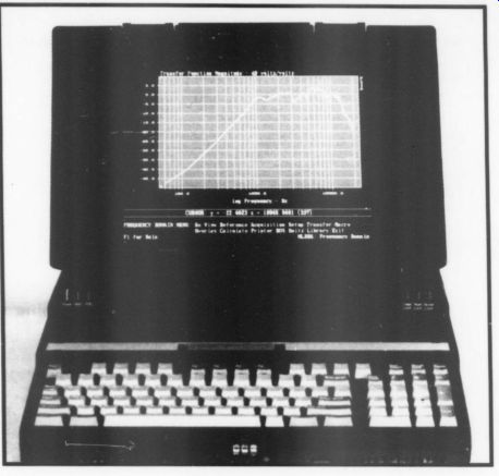

The cost-effective DRA MLSSA system consists of a custom designed plug-in card and powerful software that install into IBM or compatible personal computers including portable computers for field measurements.
The software's intuitive menu system is easy for beginners to learn yet doesn't hinder experienced users. Start making meaningful measurements in hours rather than days, weeks or months.
MLSSA.
Now even MLSSA uses advanced maximum-length sequence (MLS) measurement technology for fast noise-resistant measurements. Instrument bandwidth extends to over 40 kHz for ultrasonic coverage of tweeter drivers.
MLSSA also offers an extensive and growing list of post-processing functions including energy-time curves for room reflection analysis, STI and RASTI for speech intelligibility estimation and 3D cumulative spectral-decay plots for loudspeaker performance evaluation. Thiele-Small speaker parameter measurements are also available as an option.
To learn more call or write for literature and a free demonstration disk.
OVERSEAS DISTRIBUTORS: Germany, Austria: Harmonic Design, West Germany, Tel +49 07042/7085, Fax +49 7042/78411, England, Ireland, Hong Kong: Munro Associates, England, Tel +44 01-480 7121, Fax +44 01-702 3834; Sweden, Finland: Lab Gruppen, Sweden, Tel +46 300-16823, Fax +46 300-14246; Switzerland: ANADA AG, Switzerland, Tel +41 01/810 30 22, Fax +41 01/810 43 45; Denmark: Monitor Technology, Denmark, Tel +45 66 14 59 58, Fax +45 66 14 91 81; Norway: Ingenior Per Grov AS, Norway, Tel +47 (02) 307760, Fax +47 (02) 327743; Australia: Audio & Recording, Sydney, Tel +61 (02) 666-9935, Fax +61 (02) 666-3752; Italy: Audio Link, Italy, Tel +39 0521/598723, Fax +39 0521/598848.
DRA Laboratories
607 W. Nettletree Rd
Sterling, VA 22170, Tel (703) 430-2761, Fax (703) 430-0765
---------
When you write for HELP!!!
1. Please enclose a self-addressed stamped envelope (SASE).
2. Leave room for replies on your sheet of questions.
3. Don't ask for authors' addresses. They like their privacy too. We will forward your letter if, and only if it contains a re ply envelope. If the author lives abroad, enclose an addressed unstamped air-mail envelope and one international postal reply coupon, available at your post office.
4. Please resist the temptation to use us as design consultants, research assistants, product index clerks, project trouble shooters or equipment evaluators. Doing so slows up our editing.
5. If you have a problem with one of our circuits, fully describe the problem and what you have done about it. Include all significant voltage and/or current readings, and don't forget that SASE!
---------------
KT-2: THE BORBELY PREAMP KIT [4:85, 1:86)
Erno Borbely's preamplifier rivals commercial units costing several times the KT-2 kit price. Three requirements compete against each other in the choice of circuit topology and components. The three, sometimes exclusive, design goals are low noise, high gain and wide dynamic range. The key is the use of the best available discrete transistors rather than operational amplifier ICs.
The first stage input is directly coupled to the gates of a complementary pair of low noise JFET transistors. The circuit design, high voltage power supply and device matching, together, achieve wide dynamic range, linearity and low noise.
The second gain stage is a complementary, common emitter pair, directly driving a similar output stage. The high signal-to noise ratio established in the first stage is preserved here. Mr. Borbely uses the best available complementary bipolars: ROHMs 2SB737/2SD786 pair. They have low source impedance, good linearity and an extremely low shot/flicker noise.
The servo amplifier, an LF411CN, can null input offsets of as much as one hundred millivolts and provides DC coupled performance, eliminating output coupling capacitors.
The input circuit board also has passive high frequency RIAA rolloff. The two RIAA networks are separate, allowing cleaner implementation.
The next board contains three complementary gain stages, a servo amp and an active low frequency section of the RIAA net work. Power is 48V, about 18V higher than the first board. This board contains regulators for all gain stages.
KT-2 includes five sections for each channel. Each is built on its own board. In addition, a tape buffer, line amplifier and power supply are included. The kit comes complete with two function switches, Alps volume control, two toroidal power transformers, gold-plated connectors and precision components. An article reprint is included. The kit does not contain hook-up wire, cable, solder, housing or knobs. $650 KT-2 Sections: (1-5) Available separately. Inquire for pricing.
KT-2/KW-3: With an elegant power supply upgrade to KW-3 (see Power Supply section).
Prototype photo: not representative of kit format.
KV-3: CURCIO AUTO MUTE [1:86]
Included in the kit is a small circuit board, parts and a relay to delay the sound output for 45 seconds from Joe Curcio's Daniel tube preamp. This delay protects power amps/speaker drivers from turn-on transients. Unlike solid state preamps, which may be left on continuously without ill effect, tubed preamps should be turned off when not in use to extend tube life. Also may be used to delay any low-level stereo signal from any preamp where 15-20V DC is available. $18
KT-1: CURCIO'S DANIEL VACUUM TUBE PREAMP 2:85
Joe Curcio's no-compromise vacuum tube/semiconductor hybrid preamplifier pays special attention to the issues of sensitivity, low noise, stability and the sonic contribution of the individual components. Each channel has three gain stages. The first is a modified cascode configuration offering wide dynamic range, low noise and two possible levels of gain: either 38dB, which is sufficient for most moving-coil cartridges, or 32dB for high output cartridges. The second stage is a parallel dual triode fixed at 26dB gain. Between these stages Curcio implements the RIAA equalization with a passive RC network. Output is available after the second stage or, for an added 26dB, at the output of an identical third stage.
Output impedance in either case is 20k. The 6DJ8 dual triode vacuum tube is used throughout the amplifier.
The most notable feature of the design is the on-board regulation of each tube's B+. Filaments are powered by separately regulated DC for each channel. The power supply primary AC is switched by low voltage DC. Thus no 60Hz current is present on the main board, always a potential noise problem in low level gain stages. Within the power supply housing the filament and B + are switched by an optically coupled, zero-crossing triac and an electromechanical relay. The kit is complete with all needed parts for the amplifier and its power supply. Not included are housings for the amplifier or power supply and knobs for the rotary controls.
$385Y KS-6: CURCIO VACUUM TUBE STEREO PRE-PREAMP [5:84]
Joe Curcio addresses the problem of the low output levels of moving-coil cartridges in this two channel, two-tube amplifier. In his design a lot of attention is paid to the power supply. The power for the filaments is regulated DC. The tube's plate supply regulator is in two sections and maintains low impedance across a wide bandwidth. The kit is sold with two 6DJ8 vacuum tubes although several other types may be used. The article reprint included with the kit lists several alternates. KS-6 comes complete with two circuit boards (43%," x 2%," and 43," x 3%"), high quality metal film resistors, capacitors, phono jacks, tubes and sockets, fuse and fuse holder and all semiconductors. Housing for neither the amplifier nor the power supply is included. $135Y Prototype photo: not representative of kit format.
GKB-1: THE CURCIO DYNACO ST-70 MODIFICATION [GA 1:89]
Joe regulates all voltages in his amp design (except filaments) and drives the outputs with a constant current cascode differential driver, direct-coupled to a triode-configured output stage. Field tested for two years in over two dozen sites, the Curcio ST-70 fits within the existing chassis, using only the power and excellent output transformers from the original unit. Old Colony's kit includes boards and all needed parts right down to new mica-filled sockets for the output tubes. All parts are exceptionally high quality and the sound is the best available from the venerable ST-70 chassis. $345Y ST-70 chassis and transformer not included in kit.
KX-3: CHATER 40W ALL-MOSFET POWER AMPLIFIER [2, 3:88] Bill Chater's carefully planned design for a 40W all-MOSFET amplifier includes several novel and exciting features, such as servo controlled bias at both the driver and output stages, and a servo nulled offset to control output drift. Listening tests reveal excellent headroom and extremely fast overload recovery. Yet the circuit requires no adjustments, uses only one optional capacitor in the signal path, and is free of turn-on and turn-off thumps. Contains all parts except the chassis, hook-up wire and connectors. $180 KX-3S: CHATER 40W ALL-MOSFET STEREO AMPLIFIER [2, 3:88] Includes two KX-3s and one KX-3P power supply. $540Y Prototype photo: not representative of kit format.
KV-2S: THE LANG 20W CLASS A MOSFET STEREO POWER AMP
[2:86] Using four push/pull power MOS-FETs this 20W/channel amplifier is a beautiful modular unit with each channel on a 5.7" x 6.1" circuit card which includes direct mount arrangements for the output devices. A %"" thick L-bracket couples the power drivers' heat to an external heatsink which can be the wall of the enclosure or a rack mount panel. Ideal for multi-amplifier systems, especially electrostatic drivers. Rated by some experts as the most advanced, innovative power amp design published by Audio Amateur.
Specifications are impressive: 20W into 4-ohm loads, + 0-0.5dB @ 20Hz-20kHz; +0-3dB @ 10Hz-60kHz; Input: 0.775V = 0dB (max power); 22dB voltage gain; Input impedance: 40 k-ohm: Noise: (100mV into 40) unweighted -66dB; "A" weighted -90dB; Transient IM distortion: - 80dB; Harmonic distortion: - 84dB @ 20W; -100dB @ 4W/49. Power consumption: 80W/channel; Quiescent current: 2A/channel.
All parts supplied, two separate power supplies (+24V @ 100mA: + 15V @ 8A) with toroidal type transformers and Hitachi MOSFETs, heat-coupling bracket and article reprint. Stereo.
$285 KV-2DM: THE LANG 20W, CLASS A MOSFET DUAL-MONO POWER AMP [2:86] Contains two amplifier channels and two each of the + 15V and + 24V power supplies for dual-mono-mode operation (each channel independently powered). $350
KS-3: BORBELY DC 100 MOSFET POWER AMP [2:84]
Erno Borbely keeps the MOSFET output circuit of the Servo 100 but designs a new driver/bias section and dubs the resultant amplifier, the DC 100. The highly symmetrical circuit features floating constant current sources and a complementary pair of monolithic JFETs as the input stage. Excellent thermal tracking in this stage ensures minimal offset drift at the output in spite of the 26dB gain available at DC. My. Borbely's conservative design and insistence on stability results in a real workhorse amplifier with a strong heart. Full power output into 8-ohm is 100W, into 4-ohm it is 125W.
This power is not at the cost of THD which is 0.0025% (1kHz) and 0.0065% (10kHz). Slew rate without the input filter is 75V/uS. This kit is similar to the KS-1 in that it comes complete with board (4 1/4" x 6.5"), heatsinks, active and passive components and instructions. Power required for the amplifier is the same as for the Servo 100. Refer to the power supply section for suitable power supplies.
Single channel. $160 KS-3M: BORBELY DC 100 MONO AMP [2:84]
Includes one KS-3 and one KS-3PB power supply. $285 Two or more $270 KS-35: BORBELY DC 100 STEREO AMP [2:84] Includes two KS-3s and one KS-3PA power supply. $470
KS-1: BORBELY SERVO 100 MOSFET POWER AMP [1:84] Erno Borbely's design for a more powerful MOSFET output single channel amplifier. The circuit uses bipolar and field effect transistors to their best advantage, MOSFETs in the output section and bipolars at the input. The driver section is a symmetrically balanced amplifier with an open loop gain of 56dB over a wide bandwidth. The bandwidth is restricted at the input and the resulting rolloff at 20kHz is 3dB. Just over half the gain available is fed back.
Overall closed loop gain as a result is a clean 26dB. The amplifier design provides an input capacitor to be used if excessive DC off set is present in a preamp's output. A shorting option is provided on the PC board to remove this input capacitor if DC coupling is possible. The kit comes with the circuit board (4" x 6"), quality resistors and capacitors, heatsinks and an article reprint detailing the design and the kit construction. Requires +40V at 3A.
A suitable power supply capable of powering one KS-1 is the KS-3PB. For two channels, the KS-3PA is recommended. See the power supply section for complete descriptions. $150 KS-1M: BORBELY SERVO 100 MOSFET MONO POWER AMP [1:84]
Contains one KS-1 and one KS-3PB power supply. $275 Two or more, $260 KS-1S: BORBELY SERVO 100 MOSFET STEREO POWER AMP [1:84] Contains two KS-1s and one KS-3PA.
Prototype photo: not representative of kit format.
KP-3A: BORBELY 60W MOSFET Amp [2:82]
This kit is based on Erno Borbely's design for a single channel workhorse to drive today's power hungry speakers. Whether used in a multi-amp system with active crossover or in a simpler two amplifier passive crossover arrangement this unit provides power, fidelity and rugged reliability. As a professional designer. Mr. Borbely is quite aware of the shortcomings of bipolar power transistors. The thermal runaway and hot spot degradation of bipolars are problems avoided by the power MOSFETs chosen for this design. The amplifier's THD specifications are 0.002% @ 1kHz and 015% @ 10kHz (60W into 89). Internal slew rate is 40V/uS. This rate is limited to 2V/uS at the input by a low-pass filter. Maximum power output into a 4% load is 75W. The kit is complete with board (3 " x 6 ") and all parts except for an easily constructed air core output coil. An instructive article reprint is provided. The amplifier requires + 50V @ 2A with surge current capability several times that. A suitable power supply is the KP-3P detailed in the power supply section.
Prototype photo: not representative of kit format.
$450 One channel, $90 KM-7: CITATION 12 MOSFET MODIFICATION [2:81]
Harman Kardon's 60W/channel Citation 12 forms the basis of a new amplifier with improved performance devised by Nelson Pass of Threshold Corporation. The original Citation's power supplies and much of its circuitry remain as first designed. This modification replaces the original 40636 bipolar output power transistors with IRF-130-MOS power field effect transistors. The bias circuit is also changed. The amplifier is a significant sonic improvement over the original, particularly in the high end where the Citation 12's veiled characteristic is replaced by a detailed, somewhat sweet sound. The imaging and midrange definition also are much improved. The bass response, one of the Citation 12's strongest points, remains much the same. Distortion over most of the spectrum is lowered significantly. This package contains all parts and detailed instructions needed for the modification. $170 Prototype photo: not representative of kit format.
KK-13CH: WILLIAMSON 40/40 [4:79]
A Reg Williamson's straightforward single supply bipolar power amplifier is highly recommended to both the experienced builder and the newcomer. The new builder will appreciate the relatively simple circuit with its uncomplicated power needs. The veteran audio constructor might consider several of these in a system with active crossovers. The modest, by modern standards, output power of 40W is plenty when powering a single driver over a restricted bandwidth as in multi-amp active crossover systems. This power level is also enough for many apartment dwellers who share thin walls with neighbors. Figures for total harmonic distortion at full power output (40W/ 8-ohm) are 0.05% @ 1kHz and less than 0.1% @ 15kHz. Transistors are Toshiba high performance types, 3" x 5" circuit cards are included and all parts except heatsinks. The 65 68V @ 2A DC power requirement can be supplied by the William son designed KK-13P. $170 KJ-5-7: NELSON PASS CLASS A 40W AMP, A40 [4:78] This highly popular bipolar design from Nelson Pass of Threshold Corporation is as rugged as it is clean. Rugged because of hefty output transistors and clean because of carefully designed Class A circuitry. Mr. Pass direct-couples this amplifier to its load. selecting output transistors with six times the dissipation rating needed in normal amplifier operation. Anyone who has had to replace out put devices or speakers because of a timid designer's excessive attention to the bottom line (economic) can appreciate this. This no-compromise approach in the A40 leads to impressive THD figures. At 40W output the 1kHz distortion is 0.1%, at 10kHz the figure is an impressive 0.03%. This kit contains two boards(3"" x3") and all parts for two channels, including eight heatsinks and all parts for one +44V @ 8A (KJ-5-4) stereo power supply.
$465 West of Rockies, $KX-3P: CHATER 40W MOSFET POWER SUPPLY
[2, 3:88] Chater supply for one or two KX-3 amplifier channels.
KW-3: BORBELY IMPROVED PREAMP POWER SUPPLY [1:87] This single channel, low impedance supply was designed for the exacting requirements of Erno Borbely's moving-coil preamp (2:86, 1:87). The design utilizes polypropylene caps, 1% metal film resistors and LM317/337s in the preregulator and Signetics NES5534 in the op amp regulator. The kit includes a low profile 24V toroidal transformer, 4 " x 5 " circuit board and all board mounted components. Chassis and heatsink are not included.
$135 Two or more, $125 filter capacitors, bridge rectifier and line fuse. $175 KS-3PB: SERVO 100 OR DC 100 MONO [1, 2:84] This supply is similar to the KS-3PA but has a smaller toroidal transformer (225VA) and two 10,000xF filter capacitors. It is designed to supply a single channel of a Borbely power amplifier, Servo 100 or DC 100 or the equivalent. Separate supplies for each channel provide better performance and channel separation.
$125 KP-3P: BORBELY 60W MOSFET AMP POWER SUPPLY [2:82] This hefty unregulated power supply is conservatively designed to power two S0W Borbely power amps. It will maintain a mini mum output of 45V (bipolar) when supplying two fully loaded amplifiers (60W into 8%). The kit is complete with all parts except the filter capacitors and chassis.
TRANSFORMER 2X36V 200vA 11SVAC KL-4A: SULZER OP AMP PREAMP POWER SUPPLY REGULATOR
[2:80] This unit supplies quick acting DC regulated power, with an ultra low impedance as seen by the load of very high quality transistorized or IC preamplifiers. The impedance at the outputs (+ 15 and - 15V DC) is less than 10 milliohms from DC to 100kHz. Each output is able to source or sink up to 30mA. The regulator requires a bipolar 21V DC filtered source such as the KL-4B. $40 KL-4B: SULZER DC RAW SUPPLY [2:80] A complete kit of parts to build an unregulated bipolar DC sup ply with 20V/300mA outputs. Each output is filtered by a 5,000uF capacitor. Ideal for powering two KL-4A regulators. $60 KL-4C: SULZER DC SUPPLY [2:80] Same kit as KL-4B except a high quality, low hum and noise +22V toroidal transformer is supplied for the very highest possible performance. (See transformer section for KL-4D specifications.) $85
KK-7: WALDRON TUBE CROSSOVER POWER SUPPLY [3:79]
Designed to power the Waldron vacuum tube crossovers, this kit is capable of powering four crossover boards, a total of eight 12AX7/ECCC83 tubes. Maximum output for the supply is 300V at 70mA regulated and 12.6V DC at up to 1.5A for filaments. In addition a positive bias of 47V, regulated at 500 uA is available.
Comes complete with all needed parts, printed circuit board (5" x 5"), transformer, capacitors, semiconductors, fuse and line s1oy KE-5: OLD COLONY POWER SUPPLY A small economical bipolar unregulated supply with outputs of + 18V at 55mA each. All parts are mounted on the board (2'4" x 3"). Filtering is provided for each output by capacitor input RC networks.
$20 KJ-5-4: NELSON PASS A40 [4:78] Designed to power two Pass A40 Class A power amplifiers under their maximum rated loads. The transformer is a 500VA ILP toroidal. The kit comes complete with all parts, including four 9,000yF filter capacitors and clamps, two high current bridge rectifiers, line cord, fuse and holder. $175 West of Rockies, $180Y 118V PRI/BBV CT@ 8A KJ-8A: DYNACO MARK iii POWER SUPPLY MOD [1:78] An inexpensive way for the Dynaco Mark III owner to upgrade an already superior power amplifier. After the modification, hum and noise are down an additional 11dB, full load B + is up 10%, and the output at 20kHz is raised 4W. Response is flat within 0.05dB over the range 20Hz-20kHz. Also included are all parts necessary to add a balance control and an adjustable, independent bias control for the Mark III. $38 KF-3: GATELY REGULATED SUPPLY [2:75] A bipolar power supply capable of either + 18V or + 15V @ 100mA at the outputs. Regulation is by zener referenced pass transistors mounted on a small heatsink (supplied). Each output is shunted by 1,000xF capacitors. Kit is complete with all needed parts including transformer and printed circuit board (2" x4").
KE-2: REGULATED POWER SUPPLY [4:74] This lab quality bipolar regulator has outputs of + 15 and - 15V each capable of 1.5A. Regulation is by means of a pair of op amps referenced to an IC three-terminal regulator. The negative output is a voltage "mirror" of the positive output. This mirroring means the two voltage magnitudes will always be exactly equal. an important point for the powered device. Two LM395K ultra high reliability power transistors are the regulator pass elements. The kit comes with the board (3" x 4") and all board mounted parts.
To construct a power supply based on this regulator two additional parts will be needed: a transformer (36V CT @ 2A). and a heat sink for the LM395Ks. $51y TRANSFORMERS KJ-5-6: ILP TOROIDAL POWER TRANSFORMER: four 22V secondaries @ 5.5A, 121VA. As supplied with KJ-5-4. $75 KL-4D: TOROIDAL, +22V, VA, may be used for +18, +15 or 42V supplies up to 250mA. $55 KS-3TA: TOROIDAL. Two 40V windings @ 500VA. Powers two channels of Borbely's Servo 100 [1:84] or DC 100 [2:84] amplifiers.
$140 KS-3TB: TOROIDAL. Two 40V windings @ 225VA. Powers one channel of Borbely's Servo 100 [1:84] or DC 100 [2:84] amplifiers. $88
SBK-C1A: ELECTRONIC CROSSOVER [SB 3:82] A single channel, two-way crossover. May be built with 6, 12 or 18dB/octave rolloff. The kit comes complete with all needed parts, 4136 IC and circuit board (3" x 3"). When ordering be sure to select the corner frequency, one of the following: 60, 90, 120, 250, 500, 1k, 2k, 5k, or 10kHz. A suitable power supply is the KL-4A/ KL-4B or KW-3 or equivalent (see power supply section). $32 SBK-C1B: THREE-WAY CROSSOVER [SB 3:82] This kit is similar to the SBK-C1A but adds a midrange output.
When ordering select two frequencies from the list above. $60
STEREO, BI-AMP CROSSOVER BASS [SB 3:82) This kit provides a single bass channel made up of summed left/ right low-pass filter outputs in addition to the left and right HP outputs. Choose one frequency from the list above.
$64 SBK-A1: LINKWITZ CROSSOVER/FILTER/DELAY [SB 4:80)
A This kit is the result of a very detailed investigation by Siegfried Linkwitz into active crossover design. His special attention to group delay compensation is evident in this kit's circuitry. The detailed article reprint supplied with the kit not only outlines the design's main points and tradeoffs but also provides details on constructing an excellent 3-box speaker system. Linkwitz also cites the advantages of active over passive crossover systems. The kit includes all high quality precision components and board (5" x 8") for one channel of a three-way filter/crossover. The 100Hz and 1.5kHz rolloffs are 24dB/octave. Below 30Hz the slope be comes 12dB/octave. Delayed turn-on for the bass is provided for driver protection. A suitable power supply is the Sulzer KL-4A/ KL-4B or KW-3 or equivalent (see power supply section). Dr.
Linkwitz has become world famous for his work on crossover behavior. Single channel, $75 Two channels, $140
LOW PASS KK-6L:WALDRON TUBE CROSSOVER, Low Pass [3:79]
A variable corner frequency low-pass filter, Butterworth 18dB/octave type. Includes three-gang pot, level control, (3) frequency determining capacitors and 12AX7 tubes. Complete parts and 2%" X 4%" circuit board. Specify one frequency range per single channel kit. 19-210; 43-465; 88-960; 190-2,100; 430-4.650; 880 9,600; 1,900-21.000Hz. $60 HIGH PASS KK-6H: WALDRON TUBE CROSSOVER, HIGH PASS [3:79] * Similar to the KK-6L except high-pass type. Select one frequency range from those listed above. Single channel, $62 Waldron Power Supply KK-7 is recommended for up to four filters (a stereo, bi-amp system). For specifics on this kit see the power supply section.
KC-4A: ELECTRONIC CROSSOVER, TWO-WAY [2:72] A single channel two-way active crossover designed around the LF351 IC. The filter rolloff is 12dB/octave with corner at one of the following frequencies (choose one), 60, 120, 240, 480, 960, 1.920, 5kHz or 10kHz. These units may be cascaded for 24dB/octave rolloff. Kit is complete with all parts including board (2" x 3"). Requires a power supply, + 17V @ 25mA. Suitable supplies include the KE-5 and KF-3. S14y THREE WAY KC-4B: ELECTRONIC CROSSOVER, THREE-WAY [2:72] A Similar to the KC-4A but adds a center-pass filter. Specify two frequencies (see above, KC-4A) when ordering.
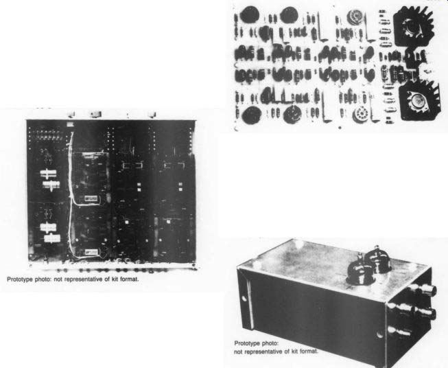
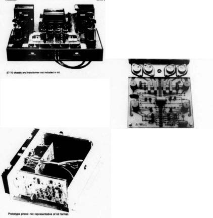
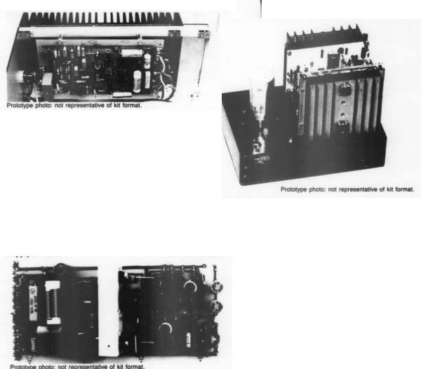
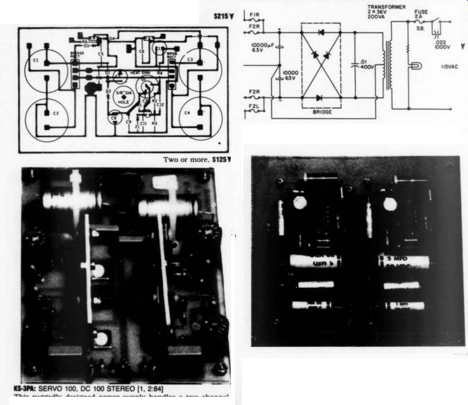
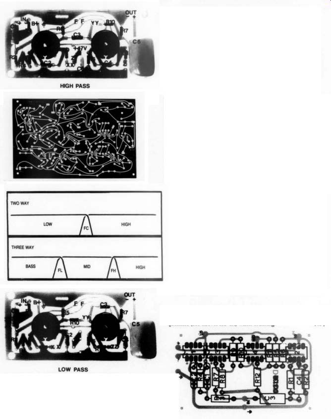
Ask TAA
By Gary Galo
Contributing Editor
ANALOG DEVICES AD711 SERIES Manufacturer: Analog Devices, One Technology Way, PO Box 9106, Nor wood, MA 02062-9106, (617) 329-4700.
ANALOG DEVICES' AD711 series of IC op amps are among the most exciting de vices of their type I've encountered in some time. The AD711, AD712 and AD?713 are the single, dual and quad versions, respectively, of this family of high-speed BIFET devices. Slew rate is typically 20V/uS with a unity gain band width of 4MHz. Noise voltage is moderately low, typically 18nV/VvHz at 1kHz. In this respect, the AD711 series is similar to other BIFET input devices, including the Texas Instruments TL071.
Many of TAA's contributors have commented favorably on the AD711 family's sonic characteristics. Since I agree with their assessments, Iwon't comment fur ther on the sound of these devices. In stead, I'll concentrate on their extremely low DC offset.
Having used BIFET input op amps for many years because I prefer direct cou pling my circuits, I thereby avoid the sonic compromises introduced by using coupling capacitors. Unfortunately, most IC op amps have an output offset too high to allow direct coupling. Gen erally, if a device or circuit has an out put offset of less than + 5uV, the circuit can be direct coupled. Back in the early 1980s I was using National Semiconduc tor LF351s extensively in electronic crossovers. At that time Old Colony was selling them for $1 each. I would hand select these devices and typically reject 50% of them for having output offset greater than 5uV. National Semiconductor did offer a selected version, the LF351AN, but it was so expensive I found it cheaper to buy a batch at $1 each and toss those which didn't meet my requirements.
TABLE 1
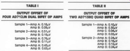
Table 1, Table 2: OUTPUT OFFSET OF TWO AD713B0 QUAD BIFET OP AMPS
Then I switched to the Texas Instruments TL071, a device similar to the LF351. But in tests, the TL071 was more stable into capacitive loads. In addition, I found 75% of them met my requirement of less than 5uV. Still, this was not an entirely satisfactory situation. Plus, if you were looking for a dual or quad device (such as the TL072 or 074) it was difficult to find a dual device with satisfactory output offset from both amplifiers, and nearly impossible to find four such amplifiers in quad devices.
The AD711 series is an ideal solution to the output offset problem. Analog Devices has solved the difficulty in matching the FET input transistors by laser trimming them during the manufacturing process. This ensures closely matched input transistors. The least ex pensive versions of these devices are those that bear the suffix “JN” and have the loosest tolerances on DC offset. The 'KN' devices have tighter tolerances.
I tested the AD711JN and AD712JN, along with the AD713BQ. The “B" devices can operate over a wider range of temperatures than the “J” and “K” devices, the former rated at - 40 to + 85°C and the latter at 0 to + 70°C.
The “Q” suffix indicated a ceramic DIP package rather than the plastic package used in the '"N” versions.
For testing I configured the devices as unity gain voltage followers operating on +16V. I tested eight AD711JNs and found all but one to have an output off set of less than 1uV, and the one device was still an acceptable 3.5uV. I put four of the quad AD712JNs to the test, and found both sections of all four devices to have an output offset of well below 1uV, and most were less than 0.5uV (Table I). Two AD713BQs were sent to me for testing, and all four sections o both devices yielded an output offset of less than 0.5uV (Table II).
The results are most impressive, in deed. Up to now, I have never used quad op amps, but the AD713 and the Linea Technology LT1058 (discussed below have convinced me a quad device can meet even the most demanding output offset requirements. Given their excellent sonic characteristics, the members of the AD711 family should find their way into many high performance audio circuits. To obtain the best sonic performance, only the highest quality associated components should be used, including metal film resistors, polypropylene capacitors, etc. In addition, use a pair of low ESR electrolytic capacitors to bypass each device, if space will permit. Values in the 220-470uF range are acceptable; the higher, the better.
Old Colony carries the AD711, 712 and 713 devices. The AD712 and 713 employ the industry standard pinouts for dual and quad devices (4558, TL074, for example). My only regret is that Analog Devices does not appear to offer a quad version which is pin-compatible with the oddball, dated, 4136 op amp.
Texas Instruments offered a TL075 version of their series to replace the 4136.
Given the superiority of the AD713, I hope Analog Devices will offer a 4136-compatible version as well.
LINEAR TECHNOLOGY
Linear Technology Corporation may not be a household word to audio amateurs, but they are gaining an excellent reputation in the audio industry for their high performance audio integrated circuits.
Over the past year or so I have had a chance to use and evaluate several Linear Technology devices, supplied to me by LT staff scientist Walt Jung (who is a household word to us).
First is a series of precision, high-speed BIFET op amps which offer serious com petition to the Analog Devices AD711 series. These are the LT1056, LT1057 and LT1058 single, dual and quad op amps, respectively. The LT1056s and 1057s I tested contain a CN8 suffix, and the LT1058s have a CN designation.
These devices feature a 14V/uS slew rate and a 5MHz gain bandwidth product, with a resulting input dynamic range (V_TH) of 0.446V. By comparison, the AD711, 712 and 713 offer a 16V/uS slew rate, 3MHz gain bandwidth product, with nearly double the Vp: 0.849V.
The LT1056 series excels in the area of DC offset. Like the AD op amps, they feature actively-trimmed input FETs.
Both dual and quad versions offer extremely low offset on each section, allowing direct coupling of all four sections of the LT1058 quad devices. In my comments on the AD op-amps I call the AD713 the first quad op amp I would consider using. I now add the LT1058 to that short list. To test for output offset I configured each section of the dual LT1057 and quad LT1058 as unity gain voltage followers. Tables III and IV show the output offset for four samples of each device, well below 1uV in each case.
If common mode rejection is critical, the LT devices are far superior to those from AD. CMR on the AD711 series is less than 40dB at 20kHz. The Linear Technology LT1056 series feature CMR of over 80dB at 20kHz, more than 40dB better than the chips from AD. If you are designing transformerless balanced in puts, the LT devices are the obvious choice.
New Buffers One of the most remarkable devices I've encountered is the LT1010CT buffer.
The LT1010 is an extremely fast (75V/ uS) device with extremely low output impedance. It can deliver + 150mA into a 75 ohm load. The LT1010 is not an op amp but a unity gain buffer designed to be used in conjunction with conventional op amps. In such applications, it is normally placed inside the feedback loop, with the op amp feeding the buffer (whose input impedance is extremely high), and the buffer, in turn, driving the feedback loop. This allows the op amp to provide the necessary voltage gain, without its performance being compromised by loading external to the circuit.
When used inside the loop, the DC off set of the circuit will be that of the op amp itself.
The LT1010CT comes in a 5-lead T0220 plastic case, with connections for positive and negative supply voltages, in put, output and bias. The external bias connection is perhaps the most outstanding feature of this device. By lowering the bias resistor to 50%, the output stage is operated pure Class A. In this case, the device will require a small heatsink, such as the 5W coolers sold by Digi-Key (don't just clip them on; bolt them with 4/40 hardware and use thermal compound).
Figure 1 shows a typical LT1010 application, in this case a high performance line-level preamp stage designed by Walt Jung. The LM334 current source, with resistor trim, biases the LT1056 op amp for Class A operation and, as such, re places the more conventional, but less elegant pull-down resistor. The resistor should be adjusted for 2mA of current.
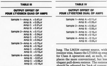
TABLE IV -- OUTPUT OFFSET OF FOUR LT1057CN8 DUAL OP AMPS
This is an excellent line-level circuit which, if powered by a low impedance supply, will deliver true high end audio performance.
Walt Jung and LT Applications Manager Rich Markell have also designed a low distortion unity gain buffer using the LT1010 with a pair of JFETS. The complete circuit, first published in Electronic Design, is shown in Fig. 2.2 The JFETs should be matched for I-D of 0.5mA. R2 may be trimmed for zero DC at the output (less than + 5uV is fine for direct coupling). The authors originally set the bias resistor at 150 ohm, but reducing the value to 500 biases the device heavily Class A and is preferred for high performance audio applications.
The same heatsinking requirements mentioned above apply here. This circuit will deliver outstanding performance in any situation where a unity gain buffer is required. I use a pair in my POOGE-4 Magnavox CDB-650 in place of the 0002-style buffer originally specified (TAA 1 and 2/88). You could also use this circuit as a tape output buffer.
Note that this buffer has no overall feed back and features an open loop THD of around 0.02%.
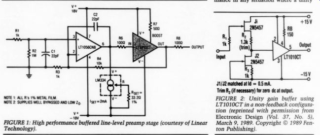
FIGURE 1: High performance buffered line-level preamp stage (courtesy of Linear Technology). FIGURE 2: Unity gain buffer using LT1010CT in a non-feedback configuration (reprinted with permission from Electronic Design (Vol. 37, No. 5), March 9, 1989. Copyright © 1989 Fen ton Publishing).
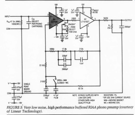
FIGURE 3: Very low noise, high performance buffered RIAA phono preamp (courtesy of Linear Technology).
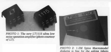
PHOTO 1: The new LT1115 ultra low noise operation amplifier (photo courtesy of LT). PHOTO 2: 1.2M Spice Macro-model diskette is free for the asking (photo courtesy of LT).
Ultra Low Noise
One of the most recent additions to the Linear Technology family of op amps is the LT1115 (Photo 1). This ultra-low noise device is virtually identical to their excellent LT1028, albeit with slightly relaxed DC specifications. Another important difference between the two is that the LT1115 is guaranteed to meet several critical audio performance specifications, both for the device itself and the application circuits provided in the data sheet.
Audio applications were not a primary emphasis for the LT1028. With a noise level of 0.9nV/VHz, the LT1115 is ideal for phono and microphone preamps. Figure 3, from the LT1115 data sheet, is a Jung-designed low-noise RIAA phono preamp using the LT1010 buffer inside the RIAA feedback loop. The low-impedance RIAA network allows full exploitation of the low-noise potential of the LT1115, and the LT1010 has more than ample current to drive it. This circuit has low enough output offset to be direct coupled.
In this circuit, the LT1115 is operated Class A using a current source consisting of the JFET and resistor. The resistor value should be selected for 2mA of cur rent, which can easily be measured with a digital multimeter. With careful component selection and a first class low impedance power supply, this circuit will deliver state-of-the-art performance.
This current source also can be used with the LT1056 in the line-level stage described above. This arrangement is, perhaps, simpler than the one shown in Fig. 1, particularly if the LM334 current source is not available.
An even easier approach is to use a JEET which, by itself, provides the necessary 2mA of current. A 2N5457 will work fine, in which case the resistor is eliminated, with the gate and source being tied together. You will have to hand select the 2N5457s for 2mA of current.
Note, the drain of the FET is tied to pin 6 of the op amp. The LT1115 data sheet contains several other excellent circuits, including a passively equalized RIAA phono preamp for moving coil cartridges, a moving coil head amplifier and a high performance transformer-coupled microphone preamp.
Voltage Regulators
Linear Technology also manufactures a variety of IC voltage regulators. The LT1086CT positive regulator is pin-compatible with the LM317. It is supplied in a TO-220 package and will deliver 1.5A of current. LT also manufactures their own version of the LM337 negative regulator, which they call the LT337AT.
I've used these adjustable regulators in several dual-polarity power supplies and have found their performance excellent.
They feature low dropout voltages, and regulation superior to the normal 371 and 337 devices. Sample regulator circuits are given in the LT data-book, but these devices can be used in any circuit specified for 317s and 337s.
Software, P Spice, the IBM PC compatible version of Berkeley's circuit analysis pro gram, is used extensively by the engineering community. Linear Technology has developed Spice macro-models for more than 40 of their IC amps. These macro-models simulate DC, AC, transient and overload characteristics of the amplifiers. LT has released these macro models on a 1.2M diskette, free for the asking by calling LT's Literature Distribution Department (Photo 2). A demonstration version of MicroSim's PSpice is also included on the disk, allowing you to try out your own circuits using LT op amps.
One of the more impressive demos on this disk plots the RIAA frequency response of the circuit shown in Fig. 3.
Figure 4 shows the measured RIAA response along with the simulation done by PSpice. Look carefully at the scale; the smallest increments are 0.2dB. The demo diskette contains a batch file for installation on your hard disk. Although it will operate in any IBM compatible computer, you really need a math co processor to run these programs in any reasonable length of time. Even an 8MHz 8088 computer with an 8087 co-processor will do quite nicely on these, al though an 80286/80287 combination (or 386/387) is even better. Without a co processor, you might as well go and make coffee while the programs are running. For more information on all of the items discussed here contact: Linear Technology Corporation, 1630 McCarthy Blvd., Milpitas, CA 95305, (800) 637-5545. Mention Audio Amateur and this column.
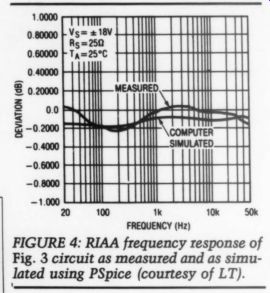
FIGURE 4: RIAA frequency response of Fig. 3 circuit as measured and as simulated using PSpice (courtesy of LT).
REFERENCES
1. Tellig, Sam, 'The Audio Anarchist," Stereophile, Feb. 1990, p. 67.
2. Jung, Walt and Rich Markell, 'Low Distortion Video Buffer,” Electronic Design, March 9, 1989, p. 90.
READERS' COMMENTS
Current Debate, Part 1 The 4/89 issue of TAA is up to its usual standard. Now I've got to decide whether or not I want to do anything to my trusty old GFA-555.
There is, however, something I feel should never have appeared in your fine magazine, at least not in its present form, which is liable to cause you some embarrassment. I am referring to Gary Galo's seemingly summary dismissal of Norman Crowhurst's book on electronic fundamentals because he (Galo) appears not to understand the meaning of conventional current in electrical engineering.
The engineering definition of current is “the net transfer of positive charge.”
{ Note the word net; it makes no difference in circuit analysis whether a coulomb of electrons goes one way or a coulomb of protons goes the other; all we are interested in is the resultant differences in, or rates of change of, charge.
It's too bad old Ben Franklin defined the electron as negative, but he did, and circuit analysis has been developed on that basis.
The conventional definition of current allows us to take voltage drops in the direction of current flow, just as pressure drops occur in the forward direction of fluid flow in the old water-pipe analogy.
Likewise, you can think of batteries, dynamos, and generators as pumps, in which flow exits the high-pressure port of the device. You should not take this analogy too far, of course, and no engineer really thinks in these terms. How ever, in hydraulics we really do have to worry about what direction the water is going, and in addition our resistances are nonlinear for turbulent flow, which is usually the case.
Regarding tubes and transistors (including diodes) in engineering circuit analysis, proper equivalent circuits are always used. Why does Mr. Galo think the arrows in the symbols for diodes, transistors, and so on point the way they do? It simply makes no difference which way the electrons are moving, and proper attention to mathematical sign conventions will always yield the right answers, provided the loop equations have been properly set up and solved.
Worrying about electron flow direction in AC circuit analysis is pointless, for the most part; here we must scrupulously observe phase as well as amplitude, and all will come out right in the mathematics.
Norman Crowhurst is one of the grand old men of audio, and to suggest that he is confused about electron flow, or that he contradicts himself in any way, is unfortunate, and incorrect in any case.
There has always been a stubborn streak in non-professionals about electron flow; without engineering training, they do not understand the mathematical basis of conventional current and assume that engineers are just being difficult when they try to explain it. There is also the assumption that only technicians really understand the equipment, and engineers are lost in some ivory tower, completely out of touch with reality. There are indeed a few of these, but most of us have our feet planted firmly on the ground.
I am also well aware that knowledge is knowledge, and one does not necessarily need to go to college to gain it.
There have been many very successful autodidacts. The advantage of a well laid-out course of instruction is that presumably the wide experience and knowledge of the good professors will have allowed them to concentrate on the fundamentals without omitting anything vital.
This letter is not to be construed as a personal attack on Gary Galo. He has contributed greatly to audio, not least his enthusiasm and his unique perspectives. He is certainly entitled to his opinions, in any case. This is a defense of Norman Crowhurst, not that he needs one from the likes of me; but I hope that this current-versus-electron-flow bugaboo can soon be laid to rest, once and for all.
By the way, I recommend the second edition of Horowitz and Hill's The Art of Electronics. It is a marvelous introduction to the subject, or a refresher, whichever is needed. However, lovers of thermionic valves won't find much mention of them here.
CHARLES L. CRAWFORD
St. Albans, WV 25177
Current Debate, Part II
With all due respect, may I play devil's advocate? | hear the sound of an axe be ing ground as I read your book reviews in the 4/89 issue of TAA. You advise readers to 'ignore any book that teaches conventional current flow."" What do you think the edifice is made of that you are standing on if not conventions? Conventions, useful assumptions, and first principles, abound in all works of man.
Electrons are one of many types of charge carriers in the audio amateur's world. Even your way of thinking of an electron may be an old convention; I have heard physicists say that an electron is not elemental.
Next to your now sharp axe, your language galls me in the consistent use of the exceedingly conventional expression, 'current flows' or the “flow of cur rent.” Current doesn't flow, charge flows, and the flow of charge is current.
The flow of the flow of charge? That sounds like nonsense. Are you concerned with what is happening and the clear description of it, or are you venting a personal frustration?
LEON G. BYERLEY III, Tucson, AZ 85716
REPLY
... with my remarks on conventional cur rent flow versus electron current flow in my last column (Ask TAA, TAA 4/89, pp. 41-42). Obviously my comments were insufficient to satisfy those who still prefer to think in terms of positive to negative, so I'll elaborate on the matter here.
In the interest of brevity, I refrained from quoting both Forrest M. Mims III and R. H. Warring. I'd like to rectify that situation now. On page 47 of Getting Started in Electronics, Mr. Mims offers the following explanation under the heading MORE ABOUT THE DIRECTION OF CURRENT FLOW (italics are the author's):
"An electrical current is the movement of electrons through a conductor or semiconductor. Since electrons move from a negatively charged to a positively charged region, why does the arrowhead in a diode symbol point in the opposite direction? There are two reasons:
1. Beginning with Benjamin Franklin, it was traditionally assumed electricity flows from a positively charged to a negatively charged region. The discovery of the electron corrected that.
(But most electrical circuit diagrams to day still follow the old tradition in which the positive power supply connection is placed above the negative connection as if gravity somehow influences the flow of a current.)
2. In a semiconductor, as shown on page 44, holes flow in the direction opposite that of electron flow. It's there fore common to refer to positive current flow in semiconductors.
3. For accuracy, in this book “current flow” refers to electron flow. But we're stuck with symbols that indicate hole flow." Mr. Mims is, in my opinion, one of the grand old men in the field of electronics (I don't know his age, but I've been reading his excellent writings for over two decades). To suggest that Mr. Mims is confused about current flow would be both unfortunate and incorrect.
In Understanding Electronics, on page 5, R. H. Warring states (italics are the vib Conventionally, DC current is regarded as being from the positive to the negative terminals of a battery or any other DC source (such as a dynamo). It is in the hydraulic circuit, but the stream is actually composed of subatomic particles or electrons. Unfortunately, after convention had established the positive to negative flow direction, it was found that this electron stream flow was actually from negative to positive. Later, on page 6, he describes how electrons move from one atom to the next and states:
'It is this movement that constitutes the electric current flowing through the circuit, the strength of the current being dependent on the number of electrons passing any particular point in the circuit in a given time." I suspect that since the Mims and Warring books were written for what Mr. Crawford describes as “non-professionals,” the above elaborations on the subject may not be taken seriously. I will, therefore, cite several books written by electrical engineers for those involved in a university education eprint ne nda or electronics.
First, Electrical Principles of Electronics by Angelo C. Gillie, 2nd 2d, 1969, published by McGraw-Hill. On page 27 Gillie states (italics are the author's):
'Prior to the development of electron theory, it was believed that current consisted of the movement of positive charges through the conductor. Since that time, as pointed out in preceding sections, it has been found that only negative charges (electrons) can be moved in a lateral direction within a metal. The fundamental difference in the interpretation of conventional current is that it flows from the positive side of the circuit to the negative terminal of the source potential, which is opposite to the lateral direction taken by electron current. This text incorporates electron current throughout." Second, Electricity and Magnetism by B. I. Bleaney and B. Bleaney, 3rd. Ed., 1976, published by Oxford University Press. On page 60 the authors state:
"In early experiments on electricity there was no evidence for the sign of the charges forming the current, since there was no means of distinguishing between a flow of positive charges in one direc opposite direction. The positive direction of current flow was therefore taken as that in which a positive charge would move in an electric field. Thus in a circuit, the conventional direction for the flow of current is from the higher potential to the lower potential: for example, from the positive pole of a battery round the external circuit to the negative pole.
It is customary to retain this convention, although the modern theory of metallic conduction shows that the positively charged ions are fixed (italics mine), while a certain number of electrons are free to move about the body of the metal. Since the electrons are negatively charged, their direction of movement is opposite to that of the conventional current flow." Third, Basic Electronics by Kloeffler, Horrell and Hargrave, 2nd Ed., 1963, published by John R. Wiley and Sons.
On page 5 the authors state (italics are theirs):
Electric conduction is the process of transferring electrons in an electric circuit. Electric current is the coordinated movement of electrons along a conductor." The paragraph goes on to explain the ampere, the coulomb and the propagation of electric waves, at which point the authors continue:
"The movement of electrons called electron current is opposite to the conventional direction of current adopted long before the electron theory was evolved. In the past many scientists and engineers have suggested that the conventional direction of current should be changed to coincide with the direction of electron movement. Although the suggestion has merit, it is unlikely to find adoption because of established practice and the fact the 12 positive ions and other positive current carriers do move in the direction of conventional current." Note that these authors offer a different view of the movement of positive ions than Bleaney and Bleaney. To the best of my understanding, Bleaney and Bleaney are correct, and I'll elaborate on this below.
Fourth, Electricity and Electronics by Saul A. Ritterman, 1972, published by Macmillan. On page 32 Ritterman states:
"The direction of current flow is an important consideration in electronic circuits. Based on our present knowledge of the structure of matter, the free electron is the principal charge carrier.
This means that in the portion of a circuit which is external to the battery, current flow should be away from the negative terminal of the battery towards the positive terminal.
"Unfortunately, early workers in electricity did not have the mass of information which we have today about the structure of the atom. Early experiments lead to the conclusion that current flowed in the reverse direction. That is, originally it was believed that current flowed from the positive battery terminal to the negative battery terminal.
"Although we now know that this original assumption was incorrect (italics mine), most books (including this one) still use the older convention for the direction of current flow. It is admittedly incorrect but there is no problem as long as we are consistent."
Finally, Electric Fundamentals and Applications by John D. Ryder, 4th Ed., 1970, published by Prentice Hall Electrical Engineering Series. On page 7, Mr. Ryder offers a similar explanation of why this mistaken assumption continues to this day:
'An electric current is conceived as movement of an electric charge. Benjamin Franklin in 1747 was one of the first to propose that an electric current be looked upon as an electric fluid passing from positive to negative terminal in a metallic circuit external to the source.
The definition of “positive” and “negative” was made in an arbitrary manner in that early day, and was based upon an observed difference in the charges held by electrified glass and hard rubber rods.
The techniques of electrical science have been built upon this assumption, and years of usage have made it a universal convention." It should be obvious, from all of the above, that electrical engineers have perpetuated, and continue to perpetuate, an incorrect theory of current flow. I fully understand the meaning of the term conventional current flow. I simply maintain that it is difficult to under stand how electron devices really operate using the antiquated convention. In particular, I find it impossible to explain the operation of the vacuum tube in terms of conventional current flow.
I believe that Crowhurst agrees with me on this point, since his explanation of the vacuum tube, as I stated in my review, is based on electron flow. I don't know how Crawford can state that Crowhurst does not contradict himself.
As Ritterman states above, we must at least be consistent in our explanations.
Changing the direction of current flow, depending on which electron device is being explained, is a definite contradiction-one which is likely to leave the student more than a little confused.
If Mr. Crawford will re-read the second paragraph of my review he will note that I also understand why the arrows point the way they do. Repeating what I wrote in the last issue: 'What he (Crowhurst) is actually illustrating here is hole movement within the diode, but this does not tell us the direction of electron movement within the circuit." A few comments about hole movement are in order. As far as scientists have been able to determine, at this point in Earth's evolution, the holes do not actually move in the physical sense.
Given that a hole is an area where an electron deficiency exists, you can view the relationship between electron movement and hole movement much like Chinese Checkers. If you accept Bleaney and Bleaney's statement that positive ions are fixed, this analogy can also be applied to the movement of positive ions in metallic conductors.
Imagine a row of atoms in which the electrons are the majority, but at the end of the row is an atom where an electron deficiency exists, leaving a hole or net positive charge. In our Chinese Checkers analogy, the electrons are the marbles and the hole is, well, the hole. The last electron (marble) moves into this hole, leaving a hole in its place. Then, the second to last electron moves into the newly created hole, leaving another hole in its place, and so forth. As you can see, the positive charges never physically move, although there is an apparent transfer of positive charge in the direction opposite to the electron movement.
The Heathkit text, reviewed at the beginning of this column, gives a similar explanation. On page 448 author Wheeler states:
"If an electron jumps from one shell to fill in a hole, another hole is created where the electron leaves the shell. The hole, therefore, appears (italics mine) to move in the opposite direction (italics Wheeler's) of the electron. If another electron moves into the hole that was just created, another hole is produced, and the previous hole appears (italics mine) to move randomly through a pure semiconductor material. Thus the terms hole flow and electron flow." Mr. Byerley's statement that current does not flow is only acceptable if cur rent flow is defined as positive to negative. If you accept the fact that the movement of electric current is the movement of electrons, then the term “flow” is entirely appropriate, since we are describing particles which are actually moving
NTS through a conductor, from one atom to the next. I realize that Mr. Byerley's point is, in part, one of semantics but several of the books cited above use the expression “current flow” and I personally have no problem with it. Mr. Byerley is correct when he suggests that our present atomic theories are being challenged on an almost daily basis. But, the notion that the electron may not be elemental does not, by itself, change what we know about the movement of electrons.
Conventions do indeed abound in the works of man. For a substantial portion of Earth's history the alleged flatness of our planet was an accepted convention.
The notion that our flat planet was the center of the solar system was another accepted convention. Fortunately, when hard evidence to the contrary convinced even the most die-hard skeptics, those conventions were discarded in favor of a more accurate view of Earth as a round body which, along with at least eight other planets, revolves around the sun.
If you accept the writings of the electrical engineers I've quoted, it becomes obvious there should be no debate on the subject of current-versus-electron flow.
Current flow and electron flow are one in the same thing, and are certainly not opposed to one another, as Mr. Crawford suggests.
In my Audio Fundamentals course I teach basic acoustic and electronic theory to liberal arts and music students. My goal as a teacher is to give my students a practical working knowledge of the basics of electricity and electronics, in as accurate a fashion as possible. I see no sense in perpetuating the past errors, especially when those explanations lead to misunderstanding and contradiction. I do discuss, albeit briefly, conventional current flow and why we now know that it is incorrect.
In many respects, audio amateurs are much like my students (my best students, at any rate). They are often not electrical engineers and they want to know what is really going on. Telling them to simply accept an incorrect explanation because most electrical engineers refuse to part with the old “conventions” is not good enough, for me or for them. In a way, this whole subject reminds me of the arguments surrounding conversion to the metric system. We know it is a vastly superior system to what we continue to use in the United States, but we refuse to change because our conventional system is so deeply imbedded in every area of technology that the conversion would cost billions of dollars and untold inconvenience.
At Mr. Crawford's suggestion I decided to investigate Horowitz and Hill's The Art of Electronics. The library at Clarkson University, our neighboring campus with a national reputation as an engineering school (formerly Clarkson College of Technology), has a copy of the first edition. This is an excellent book for those seeking information on the implementation of solid-state devices in real world electronic circuits. The book is full of sample circuits, everything from the differential inputs to ADCs and DACs. This book even discusses the cascode. Audio amateurs and audiophiles hear much about the cascode circuit, but try to find an engineering book with an explanation of its operation.
They are few and far between. TAA readers will even find a chapter on construction techniques.
The Art of Electronics is not, in my opinion, a suitable book for the beginner. The authors do not offer an introduction to the workings of electricity, an area in which the Heathkit volume reviewed earlier excels. Such knowledge is either assumed or deemed unnecessary. Horowitz and Hill also deal exclusively with conventional current flow. However, with the background pro vided by the Heathkit text, the audio amateur will find the information in The Art of Electronics extremely useful, since common circuit techniques used in so many preamp and power amp designs are explained in an extremely understand able fashion. If your preference is for electron current flow, and you understand the difference between the two approaches, it is easy to simply reverse the arrows in the diagrams to understand how the circuits really operate.
I will contact the publisher to obtain a review copy of the second edition of this useful volume and report on it in a future issue, though probably not in this column. I suspect Ask TAA has had its fill of books on electronic theory, at least for now, and we should move on to other topics. Check the Book Reviews section for this one.
Mr. Byerley”s suggestion that I am simply grinding an axe is certainly a mis interpretation of my intentions. I believe very strongly in the viewpoints I have ex pressed, not because I enjoy grinding axes, but because I have a desire to get at the truth of these matters, or at least as close to the truth as our present level of scientific knowledge permits. As a teacher and fellow audio amateur, I en joy sharing such knowledge with others, in as accurate a fashion as I can. I am also a perpetual student, learning, hope, new
AUDIO AIDS
QUIETING ZENERS
IN ESSENCE ALL ZENERS generate noise. So I recommend filtering all zeners for low and high frequencies. All zeners (most 3-terminal regulators are merely amplified zeners) should be treated as follows: existing cap, usually at power supply existing cap, usually 5-50uF tantalum, mounted at Z added 0.1uF Mylar, mounted at Z free standing zener/embedded zener/ 3-term regulator Though this modification was originally intended for RF gear, it is equally applicable to audio-noise, IM, and so on.
BuD MOIST Elko, NV 89801
CABLE CHECKING IF YOU'VE EVER TRIED to locate which of several phono cable interconnects in your stereo system has gone open or intermittent, then perhaps you'll want to build this simple little circuit. It may even save you an unnecessary trip to the repair shop the next time your stereo acts up. Of course, you could check for cable continuity using a multitester, but even test leads equipped with alligator clips can cause problems by falling off or making poor contact. Also, if you have many cables to check, the operation can become time-consuming and frustrating.
I built this device (Fig. 1 and photo) one day to locate an intermittent in one of eight phono cable pairs in my own system. I wanted something that was solid, reliable and foolproof. The circuit is basically two identical, independent continuity testers in a single enclosure.
It quickly tests both the outer (-) and inner (+) wires of both left and right channels of a stereo phono cable. Since most phono cables are sold as Siamese pairs, I thought it would be useful to test both channels simultaneously, to avoid confusion and errors while reducing the workload.
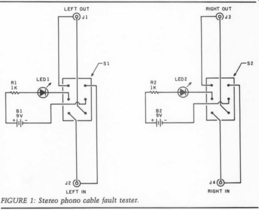
PHOTO 1: Stereo phono cable fault tester.
The device uses two 9V batteries and requires no ON/OFF switches, since no current flows unless a “good” cable is connected, completing the circuit. Since this tester is apt to sit for months or even years until needed, it is a good idea to remove the batteries after use to pre vent leakage damage. I used a green jumbo LED for the left and a red jumbo LED for the right channel continuity indicators. (Current consumption is of the order of 6.7 and 7.2mA, respectively.) Component layout is not critical, but I found it convenient to put the two dual phono jacks one above the other so the left/right IN phono plugs could be connected to the upper and the left/right ...
PARTS LIST
Numbers refer to Radio Shack catalog numbers. Substitutions may be used.
DPDT switches
green T 1 3/4 jumbo LED
red T 1 3/4 jumbo LED
1,000 ohm, 2W, 10%
carbon resistors
9V battery snaps
dual phono jack assemblies
T 3/4 jumbo LED panel lamp holders #276-080 2 9V batteries
23-583 Assorted wire, screws, nuts and bolts, heat shrink tubing, solder, solder paste, suitable enclosure, labels, optional 9V battery holders
(#270-326)
#275-8022
276-022
276-041
#271023
#270-325
#274-332
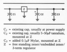
------------
OUT phono plugs to the lower assembly pair. I also used heat-shrink tubing to tidy up all the wire leads between the two switches and the jacks or the LEDs and batteries, for long-term reliability.
Once assembled, connect the batteries and switches S; and S, to either the GROUND or POS position. No LEDs should be lit. Then connect the cable under test as follows: the left and right phono plugs at one end of the cable go into the upper left and right jack pair.
The left and right phono plugs at the other end of the cable go into the lower left and right jack pair. If the cable is good, both green LEDs will light up brightly with the switches in one direction, and both red LEDs will light up with the switches in the other direction, ...
FIGURE 1: Stereo phono cable fault tester.
... even when the cable is wiggled vigorously along its entire length (most problems seem to be associated with the plugs themselves).
An intermittent will show up as a flashing green or red LED, depending on which channel has the fault. An unlit LED indicates that the cable is open. In each case the corresponding switch position will tell you whether the offending fault is in the outer shielding or the inner wire of the cable. You can then either repair or replace the cable.
As a final note, you can modify the fault tester to suit your needs. For ex ample, a guitarist might wish to eliminate the right half of the circuitry, and substitute 3/4 " phono jacks for jacks J,.,.
Or, if your cables use different plugs or plug combinations, the appropriate jacks can be substituted for or wired in parallel with jacks J,4, for added flexibility.
S. WAYNE, Cox Campbell River, BC, Canada VOW 2S6
IMPROVED SHIELDING
IN HIS EXCELLENT BOOK, Grounding and Shielding Techniques in Instrumentation (John Wiley and Sons, Inc., 1967), Ralph Morrison points out that the effectiveness of a shield (as in a shielded wire) is compromised if the shield conductor also serves as a signal carrying wire. Such is the case with our cursed "RCA“ plug system of interconnects, in which the outer shield also serves ..s the audio signal reference zero. It occurs to me that we can isolate the shield from the signal-zero conductor if we are willing to permanently affix the cable at one end, such as is commonly done with turntables (Fig. 1).
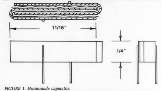
FIGURE 1: Homemade capacitor.
The signal is carried in the twisted pair portion of a “two conductor plus shield” cable. The outer shield is connected to chassis ground at its permanently affixed end and carries no cur rent. This arrangement is still a com promise at radio frequencies since the continuity of the shield is broken at the region marked X in Fig. 1. The shield can act as an antenna at radio frequencies; it should be bypassed to chassis ground as close as possible to the point where it enters the enclosure. Use a small ceramic disc, about 0.047uF and keep the capacitor leads as short as physically possible.
RON SAWYER, Seattle, WA 98144
HOME COOKING
MANY HOME EXPERIMENTERS have, at one time or another, found it necessary to improve components to complete a project over a weekend. One Sunday after noon, one of my projects used the un compromising TL070 op amp as a phono stage, which needs an external compensating capacitor. Did you ever wonder where to obtain very high quality capacitors for your op amp on a Sunday after noon? I made a successful pair in a few minutes, using basic materials and a capacitance meter to test results.
Figure 1 is a sketch of the homemade 30pF capacitors, assembled from 0.25 by 0.010" brass strip (from the local hobby shop), and ordinary plumber's 0.5 " wide Teflon thread sealing tape. Simply bend two 1 3/8 " long strips of brass nearly double, then interleave one of them with 2" of tape. Nest the remaining brass “U” inside so the tape is between all mating brass surfaces. I tapped the assembled capacitor with a hammer to supply a clamping force to hold the parts together. Solder mount leads in place, and trim away excess tape.
Tests with the capacitance meter showed 35pF or so, easily adjusted by gently sliding the two brass halves apart.
You can even adjust the caps after installation, if lead capacitance is a consideration. Note: the capacitance of parallel-plate capacitors using Teflon as the dielectric and a plate spacing of 0.020" is approximately 23pF/square inch.
The proof of the pudding is in the listening. Your brass capacitors will certainly perform with the best. Imaginative readers will further concoct all sorts of designs from plumber's tape and a variety of commonplace materials.
DARCY E. STAGGS, Orange, CA 92669
FIGURE 1: Isolating the shield.
++++++++++++++++
ASK TAA (cont)
things every day. If our body of knowledge advances to the point where new theories of electricity become widely accepted by the scientific community, I shall embrace those theories, even if they contradict my current viewpoints. But, based on our present knowledge, I stand firmly behind what I have stated here.
Finally, I find it most unfortunate that a reviewer can't make negative comments about a book or design without those comments being interpreted as a personal assault on the author. I make every effort to stick to issues in my writing, keeping personalities out of the way. I do not question Mr. Crowhurst's knowledge in the field of electronics. I simply disagree with the perpetuation of the positive-to-negative theory for the reasons cited. I, too, hope that the conventional-versus-electron flow issue can be laid to rest, but I'll refrain from being too optimistic.
Showcase
IN A CLASS BY ITSELF
by Stephen Nitikman
I BUILT THIS PAIR OF Pass Class A amps.
Note that instead of using wires across the two supply capacitors, I have used 0.25 -inch aluminum plates (Photo 1), while the power-supply connections use very short lengths of 14-gauge wire. The output connectors are gold plated, and the input RCA jacks are insulated by rubber grommets.
I wound the toroidal transformer (Photo 2) in the middle of the amp myself. For the secondaries, I used 14 gauge insulated hookup wire over the core of a broken Variac. It makes an excellent transformer, giving me more than 16A into 2 ohm per secondary winding.
The transformer has two secondaries- one per channel-which are wound bi-filar for close tracking of the center tap.
The process for making the transformer was quite simple. The core and primary of the Variac were intact, so I first covered the primary with electrical tape all the way around the core. Since I was going to use this transformer to power two channels, I wound two separate center-tapped (ct) secondaries, one for each channel.
I found that one turn of wire around the core generated exactly 0.7V. I required 44V ct, so I figured I would have to make 63 turns (44V divided by 0.7V per turn). Rather than winding 63 turns and tapping halfway through the winding, however, I opted to wind two lengths of wire together (bifilar style) and join the ends to form the center tap.
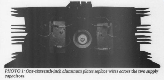
PHOTO 1: One-sixteenth-inch aluminum plates replace wires across the two supply capacitors.
In this way, I cut my chore in half, making only 32 turns per secondary. As a bonus, winding in this manner located the center tap exactly.
Of course, I could not connect just any two ends to form the center tap. To test the connection, I connected two loose ends, one from each winding, to an AC voltmeter. I then connected the other ends together, making sure that they produced 44V across the voltmeter. Properly connected, the three wires formed the secondary to power one channel.
I repeated the winding procedure over the top of the secondary (around the core) to form the secondary for the other channel. Finally, I dipped the finished transformer in varnish to keep the windings tight.
PHOTO 2: The author wound his own toroidal transformer, using 14-gauge hook up wire over the core of a broken Variac.
All the resistors are Corning metal film, and the two large capacitors on the board are solid tantalum (220uF). I bought the case, which included the side-panel heatsinks, from a manufacturer of high-quality amplifiers. This amp gets quite hot, so it will require some forced-air cooling.
For output devices, I used power Darlingtons from Lambda Electronics ( Corpus Christi, TX). The amplifier operated properly the first time I plugged it in.
Oscilloscope checks showed good wave from fidelity (using a Philips PM 5108 L function generator) past 200kHz for both channels. Sine-wave power into an 8-ohm resistive load at audio frequencies was just over 40W before clipping.
The true test of an amplifier is the quality of music reproduction. My Pass Class A amplifier has never let me down. Using a trusted pair of Tannoy speakers, my modified Marsh preamp, the Borbely servo line amp and quality input material, I have noted a lack of attenuation and no rise in response throughout the audio spectrum. The bass is tightly controlled but never boomy, the midrange is full, and the highs sparkle. The music seems to come alive, and each instrument is well defined. Clearly, this amplifier and its companion preamp are among my best efforts.
Also see: