THE BUILDER MUST ARRANGE three pairs of boards to complete a preamp chassis. I have suggested a plan in Fig. 21.
The line driver boards are located at the front of the chassis to minimize signal crosstalk by making short wire runs from the phase switches to the line driver board inputs. The line outputs can be grouped and shielded in their runs to the back panel. The RIAA boards, with or without their second-deck post-amp boards, are located at the rear panel to make short leads of the phono cartridge inputs.
One optional prototype feature is nevertheless helpful: an approximately 10 by 15.5-inch base plate of blank single-side copper circuit board material. All six signal boards are mounted on this base with 1/8-inch standoff hardware, insulated from the base plate. I wired the base plate and board assembly and then installed it in the chassis using %-inch standoffs, insulating it from the chassis. I was able to use the space beneath for cable runs.
You may run the rear panel leads via this path using Neglex shielded cable if desired. The base-plate method allows blank pieces of board shields to be soldered in place vertically between active boards if they are needed. You can use
%-inch copper tubing as signal conduits.
Solder hand-bent tubing in place before or during assembly, and draw the signal conductors through the tubing. This makes a neat 100% electrostatic shield for the signal leads, and allows re-work and changes without drilling or using mounting clamps. Connect the tubing and base plate assembly to signal ground at one point. After completing all assembly, I attached a piece of board material (insulated) to the inside of the box lid and connected it to the same signal ground point for a better shielding of the system.
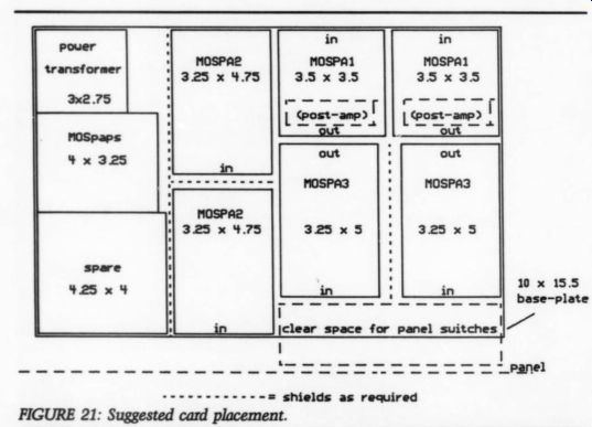
FIGURE 21: Suggested card placement.
Power Supply
The power requirement of the six circuit boards is about 9W. The voltages are delivered on four bus lines; +25V and + 15V. The regulation requirements are modest, but to set the 25V levels, regulators are used as shown in the overall circuit on Fig. 22. This dual-mono power supply form is possible by using a double secondary power transformer. The 25V regulator current demand is about 50mA each. A subsequent set of 15V regulators is used to power these slightly more critical lines.
One other consideration is the optional reed relay current. These reed relays are rated at a 24V operating voltage but will pull in at about half of that. To minimize heat and, more importantly, to control the drop-out time of the reeds, I used a 12V zener in series with the nominal 30V line voltage. This way, the reeds pull in at about +24V in the upswing of the bridge rectifier output and will hold until the 30V line has fallen to about 18V during turn-off. This results in masking any line driver output noises before the 15V lines are disturbed, so preamplifier shutdown can be quieter with the relay in operation.
The phase selector switch is another powered item (see parts list). This unit has an illuminated color chip mounted in the light path of the plastic toggle. This allows the color coding of the in-phase, mute and out-of-phase positions of the toggle. The lamp suggested in this switch frame is the #337, a miniature flange-base T1 % lamp rated at 24V, 40mA. Its power is taken from the unregulated 30V line.
Since we have two such switches for the two channels, a more balanced demand
------------------
POWER SUPPLY
PARTS LIST
----------
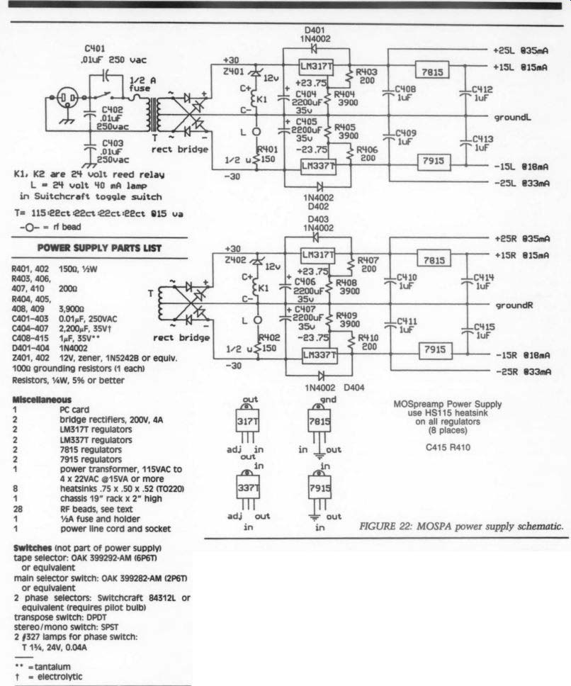
FIGURE 22: MOSPA power supply schematic.
-----------
[27]
... has wide traces for lower conductor resistances.
When you have installed the sub-assemblies, do the final power transformer wiring and make the 115V primary line connections. I have suggested a 250V AC rated capacitor across the power switch to re duce clicks from its operation. You may also want to include an EMI filter connector for the line socket. An alternative is the RF bypass capacitors shown on the 115V wires of Fig. 22. RF beads can be added at the points indicated for help in suppression of noise currents entering via the power wiring.
The base-plate construction method provides a box-within-a-box style of Faraday shield for the signal circuits. The en tire signal system including chassis-insulated input and output connectors is separate from the chassis. A resistive connection of 100 to 1,000 ohm from the base plate to chassis can establish the DC level of one to the other without providing a low impedance path for AC line currents to enter the audio system. Mount this resistor (not shown) on the back panel at a convenient hardware mounting screw. The phono cable ground lead should be provided as an insulated thumb-screw wired to the base plate.
Testing
With a complicated chassis such as this, it is probably best to complete each board and test it electrically before attempting a complete hook-up. Test the power sup ply with resistive loads, to prevent an expensive error in subsequent powering of the boards. The power supply circuit dia gram shows some nominal DC values you may expect at the various circuit points.
-----------------
Have You Seen This One?
Noise can intrude into an audio sys tem in a marvelous variety of ways.
1 encountered one rather extreme case in an early version of the RIAA boards. One channel was strikingly noisy, much more so when used BN bench After searching, 1 the circuit was only quiet on the bench, but remained noisy in the sys tem. When the trouble was found (and when the laughter subsided) it seemed fun to put it in the form of a quiz.
Was the circuit:
1. experiencing a case of radio frequency interference?
2. showing pickup from some noise on nearby wires?
3. afraid of the dark?
4. some other problem.
The answer was 3. When the chassis cover was removed the noise disappeared, only to recur when the cover was in place. The problem was a spectacularly noisy zener diode I used to develop a bias voltage for the cascode transistors. Illuminating the zener caused it to conduct smoothly, whereas a lack of photo currents left was to the zener with a resistor, in a slightly different way. The whole episode is reminiscent of the time (now long gone) when low-leakage silicon diodes were found to need a dark glass package to prevent photo verse leakage current-another wheel re-invented.
--------------------
Power each board as follows, starting with the line driver board:
1. Temporarily install 1k resistors in place of the RF beads in the output transistors' drain leads, Q311 and Q312. This will permit the circuit to tolerate a variety of possible assembly errors. (I have yet to assemble a board without some problem--it should perhaps be expected.) Monitor the 25V lines as you power up, and re-invented.
if there is enough current demand to cause the drains of Q311 or Q312 to drop below about +12 or -12V, look for the problem. The DC output level should shortly servo itself close to zero volts. If this does not happen, you have some trouble shooting to do.
2. When the circuit seems to have control of the DC situation as in step 1, proceed to an AC test for gain and output.
You must test the line driver at three gain settings, set by selecting the appropriate positions of the board DIP switches.
Since, at this point, there will not be any phase switch, you must introduce the test signal into the correct circuit point for each of the two phase inputs. Do not ground the reverse-phase input when testing in-phase gain, for if you do the in phase gain will be raised by 6dB over the correct value. A ground at the in-phase in put can be used to reduce noise if needed during test of the reverse-phase gain.
You can expect the frequency response of each amplification value to be close to that of Fig. 15 or 16 (TAA 1/90). If the high frequency response isn't quite what you expect, you can tailor the response by using slightly different values of capacitors C303 and C308. I have found it necessary to do this, because each amplifier construction has different stray capacitance, producing small effects on the high end.
Since the final adjustment should be made after installation, it might be better to leave the final choice of C303, and 308, until then.
3. Test for noise before final assembly.
The base plate and chassis shielding will probably improve the noise level, especially the hum pick-up, so don't despair if the noise level is high. When you finish the assembly, you can make a really good noise test by shorting the signal wiring at the rear panel connectors, with all shielding in place. Then you may pick up the effects of ground loops or noisy components (see sidebar, 'Have You Seen This One?").
4. You can remove the 1k-ohm resistors
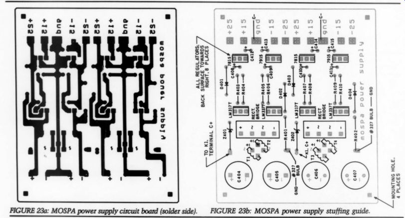
FIGURE 23a: MOSPA power supply circuit board (solder side).
FIGURE 23b: MOSPA power supply stuffing guide.
... from the Q311 and Q312 drain leads and replace the beads before final board in stallation, or you can leave them in place until all tests and wiring are complete. A belt-and-suspenders approach suggests the latter course-the 1 k-ohm resistors won't harm the performance until you make an output impedance test, or a high-level test. Since the circuit should be able to supply up to 500mA of signal current (into a 25 ohm load for instance) and should be able to supply up to at least 10V peak into 100 ohms or higher, you will want to make these tests after replacing the 1k-ohm resistors with the RF beads.
5. The other line driver board should probably be tested next, to finish that part while the test equipment and procedures are in place.
6. The tape driver boards might be next-they make use of most of the procedure now already familiar. These boards are easier to test, since there is only one phase and one gain. You should use 1k-ohm safety resistors in series with the drains of Q211 and Q212 in the same manner as in step 1, above. I've already described the expected frequency response.
7. The RIAA boards remain. If you have used the active-passive circuit version as in Fig. 6 (TAA 1/90), arrange to take the output from capacitor C22 on the card. The input should either be shorted across resistor RO2 or terminated with a load that looks like your phono cartridge.
Use short leads so as not to receive hum voltages from the test setup. Do the final noise test after putting the assembly into the chassis shielding. Again, you can protect the output transistors with temporary 1 k-ohm resistors.
8. As we did for the line driver, first be sure the circuit servo is able to pull the circuit into balance. This should occur with no more than 8 to 10V at the output of servo amplifier Al, either plus or minus to ground. The closer to ground this point runs, the better the match between input transistors Q01 and Q02. Such a match is not vital, but it feels like a good thing to have it so; any servo amp output below a few tenths of a volt implies a nice equality of the input transistors.
9. Test now for the RIAA characteristic. The best way to assure yourself this important response feature is done right is to test with an Inverse RIAA network, such as the one available from Old Colony. Introducing about a 1V sine test signal via this network sets a proper level for the test and allows you to test as though the circuit were a flat response amplifier.
Another method tests the output at the first active loop output, where the 10 ohm resistors, R31 and R32, join. The response to this point should be only that of the 50 and 500Hz parts of the RIAA curve.
That is, it should be flat with a gain of close to 52dB from DC up to the 3dB rolloff at 50Hz, and then drop to a flat response of 32dB gain at high frequencies (say 5kHz). Lowering the frequency from 20kHz downwards should show a flat response until you approach the 500Hz
-----------------
Auditioning the Chater Preamp
by Bruce Edgar, David Glacken, and Saul Sokolsky
Ever since our audiophile club heard Bill Chater's 40W MOSFET power amplifier, we were anxiously waiting to audition his companion preamp de sign. The auditioning process took place over several months that included a number of interactions which stimulated Bill to make a few improvements. When we first listened to the preamp, the imaging was very poor.
Chater subsequently found that there was sufficient crosstalk between the channels that it could be improved significantly by rerouting and shielding the signal paths. Other improvements such as lower background noise and passive RIAA equalization were easily detected as they were introduced into the preamp circuitry.
Along the way, we compared the Chater preamp to others owned by the club and club members. They included the Berning TF-12 tube preamp, and several solid-state preamps such as the PSE Studio SL, Robert Grodinsky Research RGR Model 4, and the NAD 1300. Although the top-ranked models such as Research, Krell, etc., were not included, our sample of four preamps probably covers the spectrum of pre amps used by TAA readers.
In a club demo with the PSE preamp, we found the Chater to be dramatically better than the PSE in almost every regard. It has much better depth of image, ambience retrieval and image focus. It was much smoother and notably more relaxed and unrestrained in its reproduction of complex musical passages. These differences stood out most noticeably with the Cantate Domino LP, on which the female voice sounded much more natural. The Chater also displayed more soundstage height, and its bass control is better.
The Chater bettered the PSE in essentially every aspect of music reproduction which is of importance to us.
In previous club demos, usually half of the club members could hear subtle differences between components. With the Chater, everyone heard the difference in all the aspects of imaging.
The Chater and the RGR preamps were found to be much more similar in character. They are virtually identical in their imaging properties and in the unrestrained quality of their musical reproduction. There are some differences, however. The Chater is rather warmer but duller than the RGR. That is, the sound of the Chater is more “tube-like” in quality, while the RGR, relatively speaking, has a more “solid-state” type of sound. The RGR's presentation is cooler and more etched, with razor-sharp transients.
The Chater is warmer, with a softer top end, and with less sharp (but still extremely good) transient response. Tube aficionados would argue that the Chater sounds more like live music.
The other difference noted was slightly better image focus with the Chater.
The comparison with the NAD 1300 gave similar results.
The Berning tube preamp represents the top end of our comparison price range. In contrast to the solid-state preamp comparisons, the Berning sounded sweeter and warmer com pared to the Chater. The Berning had a wider soundstage. But in many other aspects the Chater was clearly better.
It exhibited a very obvious clarity in reproduction, better focusing and stability of imaging, better resolution and detailing of sound and better dynamics. The latter feature helped the sound of many CDs.
Overall, we found the Chater pre amp to be in the middle between tube and solid-state preamps, with a slight leaning toward the solid-state end. The switching options, high power tape and line drive amps, and channel-select able phase-switching capabilities along with its sonic attributes make the Chater preamp a real winner. We consider this an outstanding preamp which very likely cannot be significantly bettered within the realm of *'af fordable” audio equipment, and which should reward its constructor with years of enjoyment and pleasurable listening. This preamp exemplifies the goals of the audio amateur hobby.
-----------------------
... turn-up frequency, where it should rise to 3dB above the high frequency plateau.
With this part of the curve in proper operation, the addition to the circuit of the output time-constant formed by R34 and C22 should result in the correct overall response. You can check against the dB values listed in Table A in the RIAA sidebar (TAA 1/90).
10. If you have elected to make the circuit with the all-passive version of the RIAA curve, it is easy to test the first active loop. This loop should have a flat gain of 32dB from below 10Hz up to about 35kHz, rolling off to a 2 or 3dB drop at about 80kHz. These high frequency details are likely to vary according to your assembly and parts variations, but the errors will not affect the RIAA result by more than a few tenths of a dB.
With the first active loop working correctly, you can then attach the small passive-equalizer board with the post amplifier parts to the circuit and test as in the procedure in step 9. Remember to transfer the servo input wire to the post amp output as described in the earlier cir cuit description. A final test would be to
measure the ability of the board(s) to develop the design output level of up to 10V peak or more. You will probably find this is easily exceeded, and distortion visible on the oscilloscope might set in at about 15V peak.
Either result is fine; the maximum cartridge output level expected is about 50mV peak, which would result in a kHz output from the RIAA section of about 2V peak. Testing at other frequencies will of course lead to other maximum input level numbers, as the RIAA curve naturally calls for this result.
Final Items
One important measurement has not been mentioned. There is a difference be tween an operating preamplifier and one with the same test results but a better sound. This difference is to be found in the crosstalk. Early listening tests of the preamp led to a vague feeling of loss in the sound, described sometimes as a loss in the midrange. This was definitely not the case, as careful measurements showed.
It was when I made a crosstalk test that I saw the probable cause.
The circuit has the ability to provide very good cross-channel isolation, but a little injudicious lead or board placement can reduce this to so-so levels. The dual mono power supply design is able to isolate conducted coupling of signals be tween the two channels. This leaves the radiative coupling to be dealt with. To test for this property, use a 20kHz sine wave test signal at about a 1V peak level as an input to one line-level channel input, and short the other channel input at the rear panel connector. Observe the no-signal channel output at its rear panel connector. There may be more 20kHz signal at this "off" channel output than you expect. It is very easy for a few picofarads of cross coupling to generate this effect.
If this is found, you must troubleshoot for its source(s), shielding inputs or boards from each other until the crosstalk drops to acceptable levels. Using the high-frequency end of the band is meant to accentuate the effect for ease in measurement. I have found that just the “straight line' coupling from one set of the stereo volume or balance control potentiometer lugs to the opposite set can give enough 20kHz signal to be seen in this test. A grounded shield of copper-clad board can be soldered into the intervening space to attenuate this cross coupling.
When you have managed to locate all the offending spots of coupling, the residual signal will be low enough to be masked in the noise level, about 90dB or more below 1V at the equivalent input point. You will then want to make the same test using the RIAA inputs instead of the line-level inputs.
When you have this final element in hand, you can at last install the preamplifier in your system and enjoy listening with a sense of accomplishment.
++++++++++++++++
Also see: