AMAZON multi-meters discounts AMAZON oscilloscope discounts
The construction of an inductor is determined largely by the frequency range in which it is to operate. In general, low-frequency inductors have many turns and employ a laminated iron core. High-frequency inductors have fewer turns and employ either an air core, powdered-iron, or ferrite. The stray capacitance between the turns and between the layers of turns is an important factor in high-frequency coils, and special winding configurations may be employed to minimize this capacitance.
Current and voltage considerations also determine the constructional features of an inductor. The gauge of the wire, for example, is selected in accordance with the amount of current the coil must carry. Receiver coils, which normally carry only a few milliamperes of current, are therefore wound from fine wire.
Transmitter coils, however, of ten carry much greater currents and are wound from heavier wire or copper tubing.
The spacing between turns, the insulation of the wire, and the insulation between layers of turns must be adequate to prevent voltage breakdown and arcing. An inductor designed for use in high-voltage circuits will therefore have heavier insulation than one designed for low-voltage applications.
LOW-FREQUENCY INDUCTORS
Inductors designed for low-frequency applications are generally large both in inductance and in physical dimensions. Such inductors include filter reactors and audio-frequency chokes. Large inductances are required to produce an appreciable amount of reactance at the relatively low frequencies of operation. These inductors therefore have many turns of wire on an iron core.
(The "iron" core is frequently siliconsteel to reduce core losses.) Since core materials possessing suit able magnetic proper ties are electrically conductive, eddy currents are induced in the core as it is cut by the changing magnetic field of the coil. These currents produce power (I^2R) losses which must ultimately be made up by the source. To minimize such losses, the core is composed of many thin slices, or laminations, which are varnished to electrically insulate them from each other. As a result, the eddy currents are conf ined and cannot circulate from one lamination to another. A higher-resistance pat hway is therefore presented to the eddy currents, the magnitude of which is consequently re duced. The result is decreased power losses in the core.
The technique of reducing eddy-current losses by dividing the core into smaller segments accounts for the powdered-iron core in some inductors designed for higher frequencies. The magnetic powder is mixed with an insulating binder material so that each magnetic particle is electrically insulated from all others. Widely circulating eddy currents are therefore prevent ed, and core losses are cor respondingly smaller. The magnetic powder and insulating binder substance are molded (usually rod shaped) to fit into the coil. This rod of core material, known as a slug, is normally mounted so that it can be moved into or out of the coil, usually by a screw. This permits the inductance to be varied. Resonant circuits are often tuned this way, and the technique is known as permeability tuning.
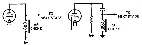
Fig. 1. D-c component of plate current saturates core in A but not in shunt-fed circuit B. (A) Pulsating direct current passes through inductor. (B) Only Alternating current passes through inductor.
CORE SATURATION
In many applications, the inductor carries a pulsating direct current (with a super imposed AC component ). An example is an inductor connected as a load in the plate circuit of an amplifier tube. The DC component tends to saturate the core, which reduces the inductance because the magnetic field in a saturated core tends to remain nearly constant. Since the constant field does not cut the turns of the inductor, it can no longer produce a counter emf. Core saturation can be prevented by using a capacitor to block the DC component and allowing only the AC component to pass through the coil. A shunt pathway, of ten a resistor, carries the DC component. Fig. 1 illustrates this tech nique for preventing core saturation in an AF choke. The same Method may be used to prevent core saturation in transformer-coupled audio amplifiers.
Another technique, commonly employed in power-supply filter chokes, is to leave a small air gap in the magnetic pat hway of the core. Since air does not saturate, the magnetic lux is limited to a less-than-saturation value.
HIGH-FREQUENCY INDUCTORS
High-frequency inductors such as RF chokes and tank coils are generally more critical than low-frequency types with respect to core losses and stray capacitance. Laminated iron cores are not used in RF components because (1) the core losses would be excessive at these high frequencies, and (2) less inductance is required than in low-frequency circuits. High-frequency inductors therefore employ either air cores, powdered-iron slugs, or ferrite cores. Ferrites are high-permeability ceramic materials made of metallic oxides such as iron, nickel, manganese, and zinc.
Because of the high resistivity of ferrites, eddy-current losses are relatively small.
Coil forms for RF applications must be made of "low-leakage" materials. Some substances which are good insulators in low frequency circuits are poor insulators in high-frequency circuits.
Low-loss materials commonly employed for RF coil forms include mica-Bakelite, polystyrene, phenolics, and ceramics. Al though paper-tube coil forms are still very popular, there is a strong trend toward the use of plastic forms. The plastic coil form is superior for high-frequency applications, and is easier to manufacture. Staple-on or riveted terminals are required with paperforms; with plastic forms, the terminals are simply em bedded in and protrude from the plastic.
The coil may be "packaged" for mechanical and environmental protection. Depending on the application, a coating of lacquer or Durez (a thermosetting plastic) may provide suicient prot ec tion. For high-reliability applications, molded or capsulated inductors are used. The molded type is similar in appearance to an ordinary resistor. In fact, some types have color stripes like resistors to indicate the value of inductance in microhenrys.
Capsulation is accomplished by placing the coil in a case, then pouring in potting compound. Coil leads are allowed to ext end out ward through the potting compound. When hermet ic sealing is required, a complet ely closed case is used, and the coil leads are brought out through feed-through terminals in the case.
The pot-core inductor has its core both inside and out side the coil. The coil winding is placed in a cup-shaped piece of core material (powdered-iron or ferrite). Another cup is placed, in ver ted, on top of the first cup. In addition, a fixed or movable rod of core material ext ends into the coil. The coil is thuscom plet ely surrounded by core material. Pot-core construction produces a highly efficient pat h for the magnetic lux.
DISTRIBUTED CAPACITANCE
As stated ear lier, pure inductance is a theoret ical concept that cannot be realized in pract ice. A pract ical inductor always has a component of resistance. It also has some capacitance--between turns, between layers of turns, between the turns and the shield (if a shield is used), and between the turns and the chassis or other nearby components. This capacitance is known collectively as the distributed capacitance. In low-frequency circuits, the efect of this distributed capacitance is negligible.
At higher frequencies, however, the capacitive reactance becomes comparable in value to the inductive reactance. At the frequency at which these two reactances are equal, the inductor becomes a resonant tank. Although this self-resonance is ad vant ageous in some applications, it is more of ten regarded as an undesirable efect of the distributed capacitance of the coil.
At frequencies above self-resonance, the capacitive reactance is smaller than the inductive reactance and tends to shor tout the coil for RF signals. RF chokes are used to "keep out " high frequency signals. The distributed capacitance, however, allows the RF signal to bypass the coil and therefore defeats the purpose of the choke. At the frequency of self-resonance and the odd multiples thereof (3f, 5f, 7f, etc.), the coil behaves like a parallel resonant (high-impedance) circuit. At even multiples (2f, 4f, 6f, etc.), the coil behaves like a series-resonant (low-impedance) circuit.
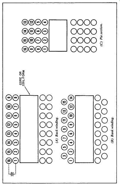
Fig. 2. Winding conigurations.
The single-layer coil has the least distributed capacitance, but it also provides the least amount of inductance for a given volume. Multi-layer coils are therefore required to produce adequate inductance for most applications. The distributed capacitance, however, is relatively large because of the capacitance between adjacent layers of the coil.
Special winding conf igurations help minimize the distributed capacitance of multi-layer coils. This is illustrated in Fig. 2.
In Fig. 2A, the second layer of turns is wound back toward the starting pointof the first layer. The last turn of the coil is therefore adjacent to the first turn, and the capacitance between these turns bypasses the entire coil. This bypassing efect can be minimized by bank winding as shown in Fig. 2B. Here, the first and last turns are more separated than the others, and the bypassing efect is reduced accordingly. Another Method of reducing distributed capacitance is to use more layers, with fewer turns on each. Here again, as shown in Fig. 2C, the separation of the first and last turns is relatively large.
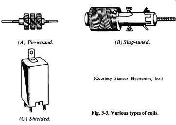
Fig. 3. Various types of coils. (A) Pie-wound. (B) Slug-tuned. (C) Shielded.
The universal Method of winding is used extensively and is a compromise between the low capacitance of the single-layer coil and the higher inductance of the multi-layer coil. This Method of winding employs a zig-zag motion so that adjacent layers are not parallel. Because adjacent turns, layer to layer, are not parallel, distributed capacitance is relatively small. This type of winding is illustrated in Fig. 3 A. Further reduction of distributed capacitance is achieved by winding the coil in sections called "pies."
This splits the capacitance into series elements, reducing total capacitance.
The use of a ferrite core also helps reduce distributed capacitance. Because of the ext remely high permeability of the ferrite core, fewer turns are needed to produce a given amount of inductance. The physical size as well as the distributed capacitance of the coil are therefore reduced.
SHIELDING
Because a magnetic field is established by current in a coil, and because this field will induce voltage in any conductor it cuts, undesirable coupling effects may occur. Magnetic coupling be tween the coils of a receiver, for example, will produce feedback from one stage to another and may cause the receiver to oscillate.
Such undesirable coupling can be eliminated by shielding each coil with a metal container that encloses the coil and therefore conines the magnetic field. Shield cans are generally made of aluminum, but copper or brass may be used. As the magnetic field of the coil cuts across the shield, it induces eddy currents in the shield material. These currents establish a "counter" magnetic field that cancels the portion of the inductor field that would otherwise escape.
Eddy currents induced in a shield represent a power loss which must ultimately be made up by the signal source. This loss can be reduced by the use of a shield large enough that it does not it the coil too closely. Another factor favoring an increased coil-to-shield spacing is the reduction of capacitance between the turns and shield (which is normally grounded).
VARIABLE INDUCTORS
Some applications, such as bandSwitching, tuning, phase shifting, and telemetering, require the use of Variable rather than fixed inductors. Several types of Variable inductors are illustrated in Fig. 4. In Fig. 4A, the inductance is changed simply by Switching to one of several taps on the coil. Another Method (Fig. 4B) employs a movable core; the far ther it is moved into the coil, the more magnetic material is placed in the pat hway of the lines of force. The number of lines therefore increases, and the inductance increases accordingly. The slug-tuned inductor is representative of this Method.
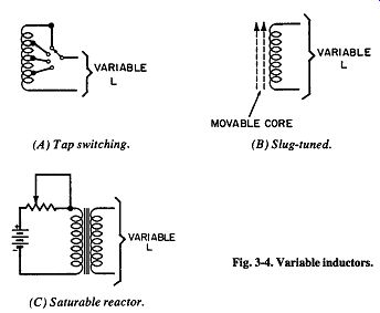
Fig. 4. Variable inductors. (A ) Tap Switching. (B) Slug-t uned. (C) Saturable
reactor.
Variable-pitch windings are used to produce a more linear variation as the slug is moved into the coil. If the turns of the coil are evenly spaced, the inductance will vary most rapidly as the core first enters the coil. The inductance will increase more slowly as the slug progresses inward. With Variable-pitch winding (turns spaced at one end and crowded at the other), nearly linear variation can be achieved.
In Fig. 4C, the inductance can be varied by changing the degree of core saturation. An increase of direct current through one of the coils increases the extent to which the core is saturated.
As the core becomes more saturated, the inductance of the second coil decreases. This type of Variable inductor, the saturable reactor, is frequently employed in industrial-control circuits and in magnetic amplifiers.
TOROIDAL INDUCTORS
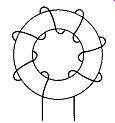
Fig. 5. Toroidal inductor.
The toroid, shown in Fig. 5, is a highly efficient shape for an inductor. The doughnut-shaped core provides a cont inuous magnetic path, and most of the lux is conined to the volume enclosed by the winding. This type of inductor has the advantage of providing a large inductance for a given physical size. The coil in Fig. 5 has only a few turns, but many more may be used (depending on the intended frequency of operation). In addition to providing large inductance in small physical size, the toroidal inductor has the further advantage of being relatively immune to stray magnetic fields. A disadvantage is its higher cost because of the greater dificulty of winding a coil on a core of this shape.
The cores of toroidal inductors can be manufactured in several ways. One Method utilizes a long, narrow strip of magnetic steel.
The strip is then rolled (like a reel of recording tape) to produce a ring-shaped core. Another Method is to stamp out washer-shaped pieces of steel, and then stack these "washers" to the desired thickness of the core. For either type of construction, the core of ten is coated with epoxy before the coil is wound. This protects the wire from sharp edges. Powdered-iron or ferrite cores also are used for high-frequency toroidal inductors.
Litz wire is frequently used to minimize skin-effect losses in toroidal inductors designed for radio frequencies up to about 1 MHz. At higher frequencies, so few turns are required that large-diameter solid wire can be used.
To cushion the coil and to protect the core from winding pressures that may alter its magnetic properties, the toroid core may be coated with silicone rubber. For environmental protection, the toroidal inductor may be either molded in Bakelite or capsulated in epoxy. A metal case may be employed when hermetic sealing is required. Both molding and capsulating are expensive procedures. When cost is a primary factor and environment al protection is secondary, the toroid may simply be mounted on a plastic coil form or at tached to a piece of fiberboard.
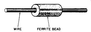
Fig. 6. Ferrite-bead inductor.
FERRITE-BEAD INDUCTORS
Typically, an inductor consists of a coil wound on a magnetic core. The greater the permeability of the core material, the fewer the turns required to achieve a given value of inductance. The development of high-permeability ferrites has made possible an inductor of inverted construction: a magnetic core surrounding a wire. As shown in Fig. 6, a ferrite "bead" is strung on a wire to produce the equivalent of a radio-frequency choke. Even though the "winding" is simply a st raight piece of wire perhaps an inch long, this choke may have an impedance of several hundred ohms in the megahertz frequency range.
For increased inductance, the ferrite bead may have several holes through it and the wire may be threaded back and forth several times. Also, several beads can be strung in series on the same wire.
The ferrite-bead inductor, sometimes referred to as an induc tance multiplier, has several advantages over the conventional radio-frequency choke. It is simple to manufacture, it int roduces very little stray capacitance, and it has almost no DC resistance.
This bead type of inductor has found application in noise-suppression, anti-parasitic, and decoupling circuits.