AMAZON multi-meters discounts AMAZON oscilloscope discounts
Like the resistor and capacitor, the inductor is a basic component of electronic circuitry. It is therefore used in practically all types of electronic apparatus. Because its reactance increases as the frequency increases, the inductor can be used to attenuate high frequencies without appreciably reducing the amplitude of low frequencies or direct current. Or, with a different circuit con iguration, it can be made to favor the high frequencies. With a capacitor, the inductor is used in tuning, bandpass, and band rejection circuits.
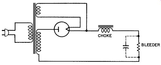
Fig. 1. Power-supply filter choke.
POWER-SUPPLY FILTER CHOKE
The ability of the inductor to oppose changes of current ac counts for its usefulness as a power-supply filter component. As indicated in Fig. 1, the filter choke is connected in series with the rectifier and voltage source (transformer secondary). During the portion of the AC input cycle when the rectifier current is increasing, the counter emf of the choke is positive on the cat hode side. This prevents the current from increasing as much as it would, were it not for the counter emf. During the portion of the AC input cycle when the rectifier current is decreasing, the count-er emf of the choke is negative on the cathode side. This keeps the current from decreasing as much as it would if the choke were not in the circuit. Because the choke at tempts to maint ain a more nearly constant current, the voltage drop across the bleeder (and also across the load) tends to remain more constant. The output voltage does not rise as high as it would without a filter choke, nor does it drop as low. The variation of output voltage (ripple) is therefore held to a small value. The filter capacitor (dotted line in Fig. 1) further reduces ripple by holding the output voltage more constant. Additional chokes and capacitors may be added to Fig. 1 for improved filtering. Although a half-wave circuit is shown, the above comments also apply to a full-wave circuit.
The filter choke is wound onto a soft-iron core, with typical values of inductance ranging from 5 to 30 henrys. In electromagnetic speakers, the field coil serves also as a filter choke.
Current in a filter choke tends to saturate the core and therefore to reduce the inductance. Some chokes have a small air gap in the iron core to reduce saturation efects. A choke designed to maint ain a pract ical minimum (critical) value of inductance at maximum current is termed a swinging choke.
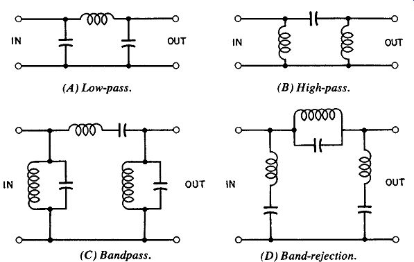
Fig. 2. Frequency-selective filters. (A) Low-pass. (B) High-pass. (C) Bandpass.
(D) Band-rejection.
FREQUENCY-SELECTIVE FILTERS
Frequency-selective filters can be classified as (1) low-pass, (2) high-pass, (3) bandpass, and (4) band-rejection. A low-pass filter (Fig. 2A) is one which will attenuate high frequencies, but will allow low frequencies to pass practically undiminished in amplitude. High frequencies are at tenuated because they en counter a high reactance in the series inductor. In addition, the high frequencies tend to be bypassed through the low reactance of the shunt capacitors. For low frequencies, the series reactance (X,) is small and the shunt reactance (Xc) is large. The cut of ffrequency (dividing point between high and low frequencies) is determined by the values of L and C. The filter of a power supply is actually a low-pass filter.
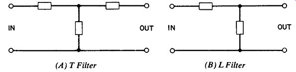
Fig. 3. t and L Filters. (A) t Filter (B) L Filter
A high-pass filter is illustrated in Fig. 2B. Low frequencies are at tenuated in it because they encounter a high reactance (Xc) in the series component and are bypassed through the low reactance (X1) of the shunt components.
The bandpass filter in Fig. 2C employs resonant circuits (Xt = Xp). It will pass a narrow band of frequencies and attenuate those above and below this band. The series-resonant circuit of fers low impedance to the frequency at which the inductive reactance is equal to the capacitive reactance (and to a narrow band of frequencies centered around this resonance point). In addition, the parallel-resonant circuits of fer high impedance to this band. Frequencies outside the passband encounter high impedance in the seies components and are bypassed through the low impedance of the shunt tanks.
The band-rejection filter shown in Fig. 2D will attenuate frequencies within a narrow band and pass those above and be low it. Here, a parallel-resonant circuit is the series component of the filter, and the shunt pat hways are series-resonant circuits.
Frequencies at and near resonance are at tenuated because they encounter a high impedance in the series component of the filter (parallel tank) and are bypassed through the low impedance of the shunt pat hways (series-resonant circuits). This band-rejection (also known as a band-stop or band-exclusion) filter can be employed as a wave trap in a receiver, to attenuate an inter fering signal.
The circuits illustrated in Fig. 2 are classified as pi filters because the coniguration of the components resembles the Greek letter pi. Other conigurations sometimes used are shown in Fig. 3; they are known as t and L filters because of their resemblance to these letters.
TELEMETRY
Telemetry is employed for remote measurement of pressure, temperature, acceleration, fluid low rate, and other physical variables. Such systems are used extensively for remote instrumentation in aircraft, missile, and satellite experiments.
For a given value of capacitance in an oscillator tank circuit, the frequency of oscillation is determined by the value of induct-ance. An application utilizing this frequency-determining characteristic is illustrated in Fig. 4. Here, a movable-core inductor is used in the tank circuit of the subcarrier oscillator of a tele met ering system.
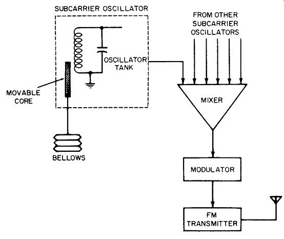
Fig. 4. Inductance-controlled subcarrier oscillator.
In Fig. 4 the movable core of the inductor is positioned by a mechanical linkage from the bellows. Since the bellows expands or cont racts in accordance with the pressure changes to which it is exposed, the frequency of the subcarrier oscillator represents the pressure. The subcarrier output is fed to a mixer along with other subcarrier frequencies representing temperature, speed, low rate, etc. These subcarriers then modulate the main carrier of an f-m transmitter. At the ground station, an f-m receiver picks up this transmission. The subcarrier frequencies are then separated and measured to provide indications of pressure, temperature, speed, etc.
PHASE-CONTROLLED RECTIFIER
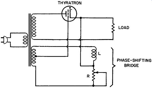
Fig. 5. Phase-controlled rectifier.
In phase-controlled rectifiers, thyratrons instead of diodes are used as the rect ifying elements. The advantage of this arrange ment is that the rectified output to a load can be controlled simply by shifting the phase of the thyratron grid voltage. A half-wave, phase-controlled rectifier is shown in Fig. 5, but the circuit can be extended for full-wave operation by the use of two thyratrons fed from a center-tapped secondary winding.
The relative values of inductance and resistance in the phase shifting bridge determine the angle by which grid voltage lags plate voltage. If this angle is small, say 30°, the positive alternation of grid voltage will occur slightly After the start of the positive alternation of plate voltage. The thyratron therefore fires (ionizes) early in the cycle as shown in Fig. 6A. Assume now that the phase-shifting bridge is adjusted to make grid voltage lag plate voltage by a larger angle, say 150°. The positive alternation of grid voltage now occurs near the end of the positive alternation of plate voltage. As indicated in Fig. 6B, the thyratron now fires late in each cycle.
A compar ison of Figs. 4-6A and B indicates that the average current through the load becomes smaller as the phase angle of the gid voltage is increased. The load is a resistor in Fig. 5, but in actual practice it might be the armature of a DC motor, for example. The speed of this motor could then be controlled simply by varying the resistance in the phase-shifting bridge. This tech nique of motor control is used extensively in industry. By eliminating the need for pulley or gear changes, it permits smooth, stepless control of motor speed.
Fig. 6. Phase of gid voltage determines firing time of thyratron. (A) Early firing. (B) Late firing.
A fixed inductor and Variable resistor are shown in the phase shifting bridge in Fig. 5. An alternative is to use a fixed resistor with a variable inductor, an ar rangement frequently employed where automatic control of motor speed is required. The inductor in such circuits is a saturable reactor (see Fig. 3-4), the DC coil of which is connected to the plate circuit of a tube. The bias of this tube therefore determines the degree of core saturation of the reactor. Since the degree of saturation determines the value of inductance, the reactor functions as a variable inductor in the phase shifting bridge. According to the signal applied to the grid of the tube that controls the reactor, the thyratron can be made to fire earlier or later in the cycle. If the motor speed is to be held constant, the control signal can be obtained from a small DC generator coupled to the motor shaft. This is now a closed-loop control system: the thyratron controls the motor, the motor drives the DC generator, the generator supplies bias for the control tube, the control tube determines the saturation of the reactor, and the reactor determines the phase angle of the thyratron grid voltage.
A change of motor speed therefore shifts the phase of the thyratron grid voltage, binging the motor back to its correct speed.
Controls of this type are used to regulate the motor speed against power-line variations and changes of mechanical load on the motor shaft.
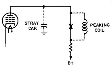
Fig. 7. Peaking coil ext ends high-frequency response.
PEAKING COILS
The high-frequency response of an amplifier stage is degraded by stray capacitance in the plate circuit. As indicated in Fig. 7, this stray capacitance shunts the plate load resistor. Since the reactance of the stray capacitance decreases as the frequency increases, the load impedance into which the tube works becomes smaller at higher frequencies. For this reason the high-frequency gain of the circuit drops off sharply.
The effect of stray capacitance can be counteracted by including an inductor in the plate circuit (Fig. 7) or in the grid circuit of the following stage. In either case, it becomes par tof the plate load impedance. Since the reactance of this peaking coil increases as the frequency increases, the load impedance of the tube does not decrease at the higher frequencies. As a result, amplifier gain does not drop off until a much higher frequency is reached. In this manner an amplifier, the gain of which does not ext end appreciably beyond the audio range, can be compensated for response up to several megahertz. High-frequency compensation of this type is commonly employed in oscilloscope amplifiers, radar receivers, and tv sets.
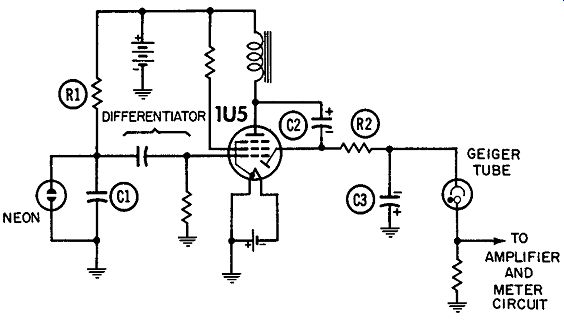
Fig. 8. Inductive kickback power supply.
HIGH-VOLTAGE SUPPLY
The counter emf of an inductor can be used as a source of high voltage for the operation of high-voltage, low-current devices such as the Geiger counter. An inductive kickback supply for a portable Geiger counter is illustrated in Fig. 8. Capacitor C1 charges through resistor R1 until the voltage across it is suf icient to ionize the neon lamp. Capacitor C1 then discharges through the ionized gas until the remaining voltage is no longer adequate to maint ain the ionization. The neon lamp now deionizes and the capacitor recharges. This repeated charge and discharge produces a sawtooth waveform across C1. In the different iat or circuit each cycle of sawtooth is conver ted to a negative pulse. As each pulse drives the 1U5 below cut off, the magnetic field of the inductor collapses. The resulting counter emf charges capacitor C2 through the diode section of the 1U5, and the charge is then transfer red through R2 to C3. The voltage across C3 (the output of the supply) is applied to the Geiger tube. Because of the rapid collapse of the magnetic field each time the 1U5 is driven below cutoff, the counter emf is large in magnitude. For this reason the output voltage of the supply is considerably greater than the voltage of the B battery.
TV APPLICATIONS
Inductors employed in tv receivers include power-supply filter chokes, tank inductances, peaking coils, delection yokes, focus coils, and width and linearity controls.
The focus coil is mounted on the neck of the picture tube so that it surrounds the electron beam. Direct current is passed through it to establish a magnetic field. Since the electrons in the beam tend to repel each other, the beam tends to spread as it approaches the screen. If this scat tering effect is not counteracted, the scanning spot on the screen will be large and the picture will lack fine detail. The magnetic field of the focus coil "squeezes" the electron beam to a smaller cross-section area. When the current in this coil is properly adjusted, the electron paths converge toward the screen to produce a small, sharply deined scanning spot.
The delection yoke contains both horizontal--and vertical deflection coils ar ranged so that their magnetic fields are at right angles to each other. Saw tooth currents are passed through these coils to produce magnetic fields that increase linearly with time.
One of the fields delects the electron beam horizontally and the other delects it vertically. Since the horizontal sawtooth is much higher in frequency (15,750 Hz) than the vertical sawtooth (60 Hz), the beam sweeps across the screen many times during each of its vertical excursions. As a result, the scanning spot traces many vertically displaced horizontal lines.
As shown in Fig. 9, the width control is connected across a portion of the secondary of the horizontal-output transformer.
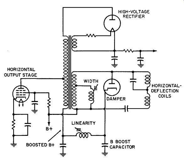
Fig. 9. Deflection, width, and linearity coils.
This secondary supplies delection current to the horizontal coils in the yoke. Because it shunts a portion of the secondary winding, the width coil limits the magnitude of the signal coupled to the yoke. The deflection signal (and the width of the picture) can therefore be controlled by varying the inductance of the width coil.
Boosted B voltage for the plate of the horizontal-output tube is produced by charging the boost capacitor through the damper diode. The source voltage of this charge is the B supply in series with the voltage in the output-transformer secondary. The boost capacitor therefore charges to the sum of these two voltages. A ripple component appears in the boosted voltage, at the frequency of the horizontal sawtooth. This ripple is shifted in phase by the inductance of the linearity control, and the amount of shiftis determined by the amount of inductance. By proper adjustment of this control, the plate voltage of the output tube can be made to vary during the sawtooth cycle to improve the linearity of the sawtooth current needed for beam delection.
MAGNETIC AMPLIFIERS
The inductance of a saturable reactor decreases with an increase in core saturation. This characteristic is utilized in magnetic amplifiers. In the two typical circuits shown in Fig. 10, a few milliamperes (or even micro-amperes) of current through the control winding can control amperes of current through the load.
A small increase in control current, for example, will increase the core saturation. As a result, the inductance of the load coil will decrease. Since there is now less reactance in series with the load, the load current increases accordingly.
The load coil of the reactor is center-tapped, and the diodes are connected so that current through the two halves is in a direction that aids the control current. Since the load current helps to saturate the core, these circuits are referred to as self-saturating magnetic amplifiers. The load in Fig. 10 is shown as a resistor, but in practice it may be a relay, solenoid, motor, furnace heating element, etc. Alternating current lows through the load in Fig. 10A. The one in Fig. 10B, which provides both control and rectification, is used for controlling current through a DC load.
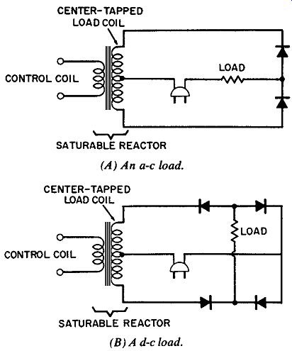
Fig. 10. Magnetic amplifiers.(A) An AC load. (B) A DC load.
Special core materials have been developed for use in magnetic amplifiers. Typically, they are such that the core suddenly saturates when current exceeds a critical value. This can be compared to the sudden "firing" of a thyratron. An additional bias winding is of ten included on the reactor. The magnitude of the bias current determines whether the reactor "fires" early or late during the AC supply cycle.
Like vacuum-tube and transist or amplifiers, magnetic amplifiers can be connected in cascade for increased gain. The load in Fig. 10B, for example, may be the control coil of a second stage of the same type. Likewise, the control coil of a third stage can be connected as the load of the second stage.