AMAZON multi-meters discounts AMAZON oscilloscope discounts
When the magnetic field of an inductor changes, the lines of force cut across the turns and induce a voltage (counter emf) in the coil. Furthermore, the changing field also will induce a voltage in any other nearby coil. This is the principle of transformer action . A transformer consists of two or more coils on the same core, or at least close enough so that the flux lines of one coil will cut the turns of the other.
TURNS RATIO
The transformer coil to which the input voltage is applied is designated the primary winding. Current through it establishes a magnetic field that induces voltage in the other coil (secondary winding). Because the magnitude of the induced voltage depends on the number of turns on the secondary as compared with the number on the primary, the turns ratio is an important characteristic of the transformer. It is defined as the ratio of the number of primary to the number of secondary turns:
turns ratio =-
Ns where, Np is the number of turns on the primary, Ns is the number of turns on the secondary.
If the secondary has more turns than the primary, the transformer has a step-up ratio. A turns ratio of 1:3, for example, indicates that the secondary has three times as many turns as the primary. A step-down transformer has fewer turns on the secondary than on the primary. A turns ratio of 20:1 therefore indicates that the secondary has one turn for every twenty on the primary.
In general, step-up transformers are used to increase voltage, and step-down transformers to decrease it. Transformers with 1:1 ratios are sometimes employed when it is desired to ret ain the same amount of voltage but to isolate one circuit from another.
VOLTAGE RATIO
Because the voltage induced in the secondary of a transformer may be either larger or smaller than the voltage applied to the primary, the transformer can be regarded as a voltage-changing device. A transformer for operating a neon sign, for example, produces thousands of volts output by Stepping up the power-line voltage (115 vac). By contrast, a filament transformer Steps down the line voltage to 2.5, 5, or 6.3 volts, or any other value required by the heat ers of the tubes.
Since the magnitude of the voltage induced in a coil depends on the number of turns being cut by the magnetic field, a secondary winding with many turns will have more voltage induced in it than a secondary with fewer turns. If, for example, the magnetic field induces a tenth of a volt in each turn of the secondary, a 2000-turn secondary will have 200 volts induced in it, and a 3000 turn secondary will have 300 volts induced. Mathematically, the voltage ratio (primary to secondary) is equal to the turns ratio:
E
£=
N, where, Np and Ns are the number of turns of the primary and secondary, Ep and Es are the voltages of the primary and secondary respectively.
In the example shown in Fig. 1, the voltage induced in the secondary can be determined as follows:
= 345volt s
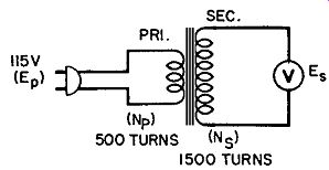
Fig. 1. Step-up transformer.
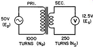
Fig. 2. Step-down transformer.
As indicated in the calculation above, the secondary voltage is three times as great as the primary voltage because the secondary has three times as many turns as the primary. In practice, the secondary voltage is somewhat less than the calculated value.
If a load is connected across the secondary, the resulting current will produce an IR drop in the resistance of the secondary winding. For this reason, the secondary voltage decreases when a load is connected. In a well-designed transformer, however, this decrease is negligible. The transformer designer can anticipate and compensate for the decrease by slightly increasing the number of secondary turns.
A Step-down transformer is shown in Fig. 2. Here the secondary has only one-fourth as many turns as the primary. Secondary voltage is therefore equal to one-fourth the primary voltage:
E 's 50 1000 250 50 X 250 1000 12.5 volts
CURRENT RATIO
Although a transformer can increase voltage, it does not provide "something for nothing."
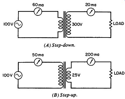
Fig. 3. Current ratios. (A) Step-down. (B) Step-up.
The voltage increase is accompanied by a current decrease. The current drawn from the secondary wind-ing is determined by the load connected to it, but the primary current will be greater than the secondary current in the same ratio that the secondary voltage is greater than the primary voltage. If, for example, the secondary voltage is four times as great as the primary voltage, the primary current will be four times as great as the secondary current. A transformer that has a Step-up voltage ratio therefore has a step-down current ratio.
In the example shown in Fig. 3A, the secondary voltage is three times as great as the primary voltage. If a load connected to the secondary draws 20 milliamperes of current, the primary current will be 60 milliamperes. In Fig. 3B the secondary voltage is one-fourth the primary voltage. If the load connected to the secondary draws 200 milliamperes, the primary current will be one-fourth this value, or 50 milliamperes.
Mathematically, the current ratio is related to the turns ratio as follows:
2? =3
…where, Np and Ns are the number of turns of the primary and secondary, I p and Is are the currents of the primary and secondary.
In practice, the primary current is slightly greater than the calculated value because the primary draws additional current to make up for core losses. For this reason, the output power of the secondary (Es times Is) is always less than the input power to the primary (Ep times Ip). The ratio of output power to input power is the efficiency of the transformer and is generally expressed as a percentage:
power out E- x !? % efficiency =---x 100 =-r-r x 100 power in Ep x Ip
For iron-core transformers, the efficiency of ten exceeds 90%.
IMPEDANCE MATCHING
Because it can make one value of impedance appear to be another value, the transformer is useful as an impedance-mat ching device. This impedance-changing characteristic of the transformer is illustrated in Fig. 4. In Fig. 4A, a 100-volt source is connected to "something" inside the box.
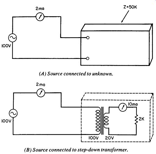
Fig. 4. Relected impedance. (A) Source connected to unknown. (B) Source
connected to Step-down transformer.
Since this "something" draws 2 milliamperes of current from the 100-volt source, its impedance is 50,000 ohms:
E 100 Z I.002 50,000 ohms
Fig. 4B shows that this 50,000-ohm "something" is actually a 5:1 Step-down transformer with a 2000-ohm impedance connected across its secondary. Since the secondary output is 20 volts, the 2K load draws 10 milliamperes of current. Furthermore, since the turns ratio is 5:1, the primary current is one-if th the secondary current, or 2 milliamperes. The 100-volt source there fore "sees" an apparent impedance of 50,000 ohms rather than the actual impedance of 2000 ohms. The apparent impedance is usually referred to as relected impedance. In other words, 2000 ohms in the secondary is relected as 50,000 ohms in the primary.
Numerically the impedance ratio is equal to the square of the turns ratio. In the above example, the turns ratio is 5 and the impedance ratio is therefore 25 (50,000 ohms to 2000 ohms).
Expressed as a formula, this relationship is:
where, Np and Ns are the number of turns of the primary and secondary, Zp and Z5 are the impedances in the primary and secondary.
Example: What value of impedance is relected into the primary of a 9:1 Step-down transformer with a 10-ohm load across the secondary?
Solution:
WNa2 Zp
'M v « 10 \ \ ) Zp To = 81 Zp
= 10 x 81 = 810 ohms
A typical use of an impedance-matching transformer is shown in Fig. 5. The transformer is used to match the low impedance of the speaker to the higher impedance of the output tube. Since the turns ratio is 40, the impedance ratio is 402, or 1600. The 4-ohm voice coil therefore relects an impedance of 6400 ohms into the primary, a reasonable load impedance for the output tube.
AF TRANSFORMERS
Audio-frequency (AF) transformers are used for interstage coupling and for coupling microphones to amplifiers, and amplifiers to speakers. Both step-up and step-down ratios are employed, the former for increasing the signal level and the lat ter for im pedance-mat ching applications. These transformers have laminated cores of iron or steel. Silicon-steel is preferred, to reduce core losses at the higher audio frequencies.
Audio-frequency transformers are physically large except for the miniaturized types designed for transist or circuits. In vacuum tube amplifiers, interstage transformers of ten have a Step-up ratio (typically 1:3) to increase the signal voltage. In transistor amplifiers, however, Step-down transformers are frequently employed to match the low input impedance of the transist or to the higher output impedance of the preceding stage.
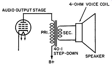
Fig. 5. Impedance-matching transformer.
Ideally, the AF transformer should have a lat response through out the audio range. In practice, however, the response tends to fall of fat the low and high ends of the audio spectrum. Low frequency response drops because the inductive reactance is small at these frequencies, and the amplifier therefore works into a smaller load impedance. This can be corrected by increasing the number of primary turns to increase the reactance. The distributed capacitance, however, also will increase, and high frequency signals will be bypassed through this capacitance.
Improved low-frequency response is therefore obtained at the expense of high-frequency response.
A bet ter way of increasing primary inductance is to use core material of higher permeabilit y. A number of nickel-iron alloys are available, some with permeabilit ies approaching 1,000,000.
Higher primary inductance can therefore be obtained with fewer turns and consequently with less distributed capacitance. The self-resonance of the transformer windings can sometimes be utilized to improve the high-frequency response.
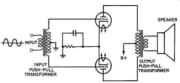
Fig. 6. Push-pull transformers.
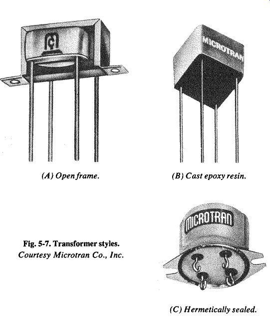
Fig. 7. Transformer styles. Open frame. (B) CaStepoxy resin. (C) Hermetically
sealed.
Push-pull transformers have a center tap on either the primary or secondary. An input push-pull transformer, shown in Fig. 6, has a center-tapped secondary to feed the two grids 180° out of phase with each other. The output push-pull transformer has a center-tapped primary winding. Each tube draws current through half of this primary. Although the tubes draw current in opposite directions through their respective halves, the current through one-half increases when the current through the other half decreases. An additive effect is therefore produced to provide an increase of output as compared to a single-ended stage. The output push-pull transformer in Fig. 6 has a Step-down ratio to match the low impedance of the speaker voice coil.
Fig. 7 shows several styles of transformer construction and packaging. Open-frame construction is illustrated in Fig. 7A, caStepoxy resin protects the transformer in Fig. 7B from extremes of temperature and humidit y, and hermetic sealing is illustrated in Fig. 7C.
RF AND IF TRANSFORMERS
Laminations of nickel-iron alloy such as those used in AF transformers are not suit able for RF or IF transformers. At these higher frequencies, eddy-current losses would be intolerably high. The nickel-iron alloy, however, can be produced in the form of fine particles, and coated with an insulating material and binder. It can then be molded into a rod-shaped core to it inside the coil.
This core of powdered iron has relatively little eddy-current loss; the insulating material between the particles produces the effect of a high-resistance core. The core may be threaded so that it can be turned into or out of the coil. This method of varying inductance is commonly employed in IF transformers.
Intermediate-frequency transformers for communications receivers (as distinguished from home entertainment receivers) use temperature-stable ferrites rather than powdered iron. Used with temperature-compensating capacitors, ferrite-core coils assure stability of tuning. Ferrites are combinations of metallic oxides such as iron, nickel, manganese and zinc, pressed into the desired shape. Because ferrites have high electrical resistivity, eddy current losses are low. It is therefore unnecessary to powder the ferrite core.
At frequencies above about 50 MHz, magnetic cores introduce considerable losses. Unless high-grade core materials are used, the Q of the coil may be less than that of an air-core coil. At these frequencies, magnetic cores should be used only for fine adjustment of frequency rather than for wide-range variation.
Non-ferrous core mateials such as copper or brass permit adjustment of inductance without int roducing magnetic losses (Although they do produce eddy-current losses).
Skin-effect losses and distributed capacitance become significant at radio frequencies. These effects can be minimized by the use of Litz wire, hollow tubing, and special winding conigura tions as described in Section 3. Radio-frequency transformers are usually shielded, as indicated in Fig. 8, to reduce undesirable coupling and feedback effects.
Radio-frequency transformers are used for interstage coupling and for coupling a signal to or from an antenna. One or both windings of the transformer may be shunted by a tuning capacitor.
This combination of inductance and capacitance constitutes a resonant tank which tunes the circuit to a narrow band of frequencies.
The front end of a radio receiver in Fig. 9 shows some typical uses of RF transformers. T1 couples the signal from the antenna to the grid of the RF amplifier. The secondary of this transformer is tuned by one section of the tuning capacitor and its trimmer.
This tank selects the desired signal from among the many signals in the antenna circuit.
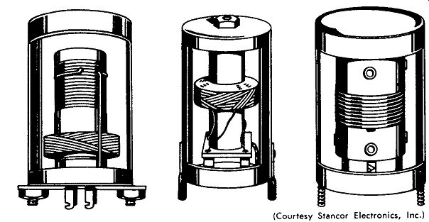
Fig. 8. Shielded RF transformers. (Courtesy Stancor Electronics, Inc.)
Transformer T2 couples the RF signal from the plate of the amplifier to the grid of the conver ter. Again, the secondary is resonated by the tuning capacitor for improved selectivity. T3 is the oscillator transformer. The cat hode and first two grids of the conver ter tube function as a triode oscillator, the second grid operating as the triode plate. Oscillator "plate" current through one winding of T3 induces a voltage in the other (control-grid) winding. As a result of this feedback, the circuit oscillat es and the electron st ream in the conver ter is modulated at the frequency of oscillation. The grid tank of the oscillator is tuned by another section of the same Variable capacitor that tunes the RF and con ver ter stages. The oscillator frequency therefore changes as the receiver is tuned from one station to another. A trimmer and padder in the oscillator tank are adjusted to make the local oscillator "track" with respect to the tuning of the RF and converter stages.
When these tracking adjustments are correct, the oscillator frequency will always differ by a fixed amount from the signal frequency being received. This fixed-frequency difference is the intermediate frequency (IF ) to which transformer T4 is tuned.
Intermediate-frequency transformers are similar to RF transformers but are designed to operate at a fixed, or int ermediate, frequency equal to the difference between the RF signal and local oscillator frequency. In broadcast-band receivers, the intermediate frequency is commonly 455 kHz. In other types of equipment (f-m, tv, and radar, for example), the int ermediate frequency may range from 10 to 60 MHz. As indicated in Fig. 9, both the primary and secondary of the IF transformer are tuned-either by tr immer capacitors as shown, or by movable slugs in the coils.
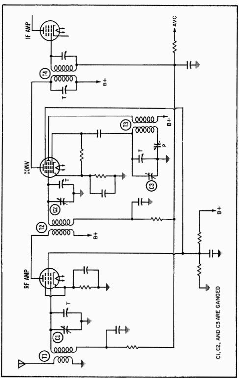
Fig. 9. Front end of radio receiver.
A modulated radio signal contains sideband frequencies as well as the carrier. Even After this signal has been conver ted to an int ermediate frequency by the action of the local oscillator, it still includes sidebands above and below the int ermediate frequency. The response of the IF stages must therefore be sufficiently wide to include these side-band frequencies. In communication receivers, int elligibility is the primary requirement and a narrow response is adequate (and also desirable, to permit the re ceiver to separate the desired station from other stations operating on nearby carrier frequencies). In broadcast receivers, tone quality is important. The response must therefore be wide enough to include the sidebands cor responding to the high audio frequencies. In tv receivers the IF response must be wider to ac commodate the sidebands corresponding to the line detail of the picture. This requires a bandpass approximat ely 4 MHz wide. By contrast, the entire standard radio broadcast band is approximately 1 MHz wide.
The bandpass of an IF amplifier can be widened by (1) connecting loading resistors across the tanks to lower the Q, (2) stagger tuning the IF stages, or (3) increasing the primary-to-secondary coupling of the IF transformers. Stagger tuning is accomplished by tuning successive IF stages to slightly diferent frequencies, allowing the amplifier to respond to a wider band.
The efect of increased coupling in IF transformers is illustrated in Fig. 10. If the primary and secondary are loosely coupled, the selectivity curve will be as shown by curve A. If the primary and secondary are brought closer toget her (tighter coupling), the selectivity curve widens and the response increases as shown by curve B. At critical coupling, the amplitude of this curve is maximum. If the coupling is increased beyond the critical value (overcoupled), the selectivity curve becomes wider but develops a double hump (curve C). Although some IF transformers are constructed to permit variation of the primary-to-secondary coupling, these are exceptions. More of ten, the degree of coupling is determined by the designer, and the transformer built accordingly.
The Q of the tank coils also determines the width of the band pass response. In general, communications receivers employ high-C? coils for narrow response, and broadcast receivers employ tanks of lower Q for wider response.
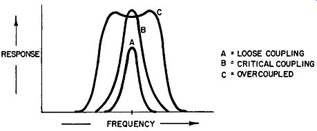
Fig. 10. Effect of coupling on bandpass response.
A = LOOSE COUPLING; B = CRITICAL COUPLING; C * OVERCOUPLED
POWER TRANSFORMERS
The power transformer is a voltage-changing device which supplies the operating potentials in radio receivers and other types of equipment. Typically, the transformer has a high-voltage secondary (200 to 400 volts), the output of which is rectified to supply the B voltage for the plates and screen grids. In addition, the transformer has one or more low-voltage secondar ies to energize the heaters of the tubes. In some types of equipment, separate transformers are employed for the B supply and for the heater voltages. More of ten, however, a single transformer with multiple secondaries is employed. A typical receiver-type power transformer is illustrated in Fig. 11. The high-voltage secondarySteps up the 115 volts alt enating current from the line to 350 volts on each side of the center tap (700 volts total). The center tap is provided for use with a full-wave rectifier. A 5-volt secondary supplies heater power for the rectifier tube, and a 6.3-volt winding supplies heater power for the other tubes. Heater windings are sometimes center-tapped to simulate a tap on the heater.
This is useful for reducing hum. Several taps may be provided near one end of the primary winding (for use in localities where the line voltage is unusually high or low). Since switching to a different tap on the primary is equivalent to changing the turns ratio, this technique compensates for abnormal line voltage.
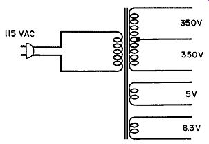
Fig. 11. Typical power transformer.
The gauge of the wire used for the various transformer windings is selected on the basis of expected current drain. Heater windings, for example, are wound with heavier gauge wire than the high-voltage secondary. Total heater current of the tubes in a receiver is generally several amperes. In contrast, total plate and screen currents rarely exceed a few hundred milliamperes.
Transformer wire is enamel-insulated. This insulation and the insulation between the layers and between the windings and the core must be adequate to prevent arcing. The high-voltage secondary is most critical with respect to insulation requirements because the potential between opposite ends of this winding is generally 500 to 1000 volts. This is one reason for the use of separate plate and heater transformers in high-voltage equip ment such as large radio transmitters.
Most of the magnetic lux produced in the transformer is confined to the iron core. Some flux, however, is established in the air around the transformer, and this flux will induce "hum" voltage in nearby wires and other components. For this reason, the transformer is usually encased in a metallic shield. In addition, an electrostatic shield is sometimes employed between the primary and secondary windings to prevent RF and noise voltages from entering through the power lines.
Power-transformer characteristics are specified according to the voltage and current ratings of the windings. A typical rating, for example, would be 375-0-375 volts at 150 ma, 5 volts at 2 amps, and 6.3 volts at 6 amps. This indicates that the high-voltage secondary is center-tapped and produces 375 volts in each half.
This voltage is specified at the rated value of current drain (150 ma). If the current drain is less than the rated value, the secondary voltage will be somewhat higher because of the re duced IR drop in the winding. The above ratings also indicate that the transformer has two heater windings with 5- and 6.3-volt outputs (at 2 and 6 amperes, respectively).
The ef iciency of a transformer is limited largely by its core losses. Research by transformer and steel manufacturers has led to the development of improved core materials and therefore to more ef icient transformers.
A principal source of core loss (explained briefly in Section 2) is hysteresis. This type of loss occurs because the core ret ains some of its magnetic lux After the current that produced it has been reduced to zero. As a result, each alternation of input power must overcome the magnetic lux of opposite polarity leftf rom the preceding alternation. The expenditure of power to accom plish this is the hysteresis loss of the core. The greater the residual magnetism in the core, the greater the power required to overcome it when the current reverses. Hysteresis loss also increases with an increase of frequency (at higher frequencies, the magnetic flux of the core must be reversed more times per second).
Another form of core loss occurs because the core material is electrically conductive. Current is therefore induced in the core by the Alternating magnetic field. The input power expended in inducing these eddy-currents is wasted because it does not produce any useful output from the transformer; Eddy-current loss can be reduced by the use of laminated core material of low conductivity. A laminated core consists of thin slices of core material insulated from each other to increase resistance to eddy currents. Both hysteresis and eddy-current losses manifest themselves as heat in the core.
The "iron" core of a transformer is usually siliconsteel. About three or four percent of silicon is added to the steel to increase its resistivity, reducing eddy-current losses. The core material is further improved by grain or ientation. Grain orientation, accomplished by cold-rolling and heat treating, aligns the crystals of steel in the direction in which they can most easily be magnetized.
The resulting steel therefore has a preferred or easy direction of magnetization; a characteristic called anisotropy. The reduced hysteresis losses in grain-oriented steel have led to increased use of 400-Hz transformers in military and airborne equipment. The advantage of 400-Hz operation over the usual 60-Hz operation is the significant saving in size and weight. All other things being equal, a 400-Hz transformer requires much less iron than the 60-Hz type. Before the development of grain-or iented steel, increased hysteresis loss at 400 Hz voided the advantage of lower weight. Now, even 800-Hz operation seems attractive.
C-core construction best utilizes the advantage of grain-oriented core material. The grain-oriented steel is produced in a long, narrow strip. This ribbon of core material is then rolled up (like a reel of recording tape) to produce a circular--or oval-shaped core. The core is then cut in half to produce two C-shaped pieces.
After the prewound coils are placed on the core, the two halves are it ted toget her again. The advantage of this tape-wound core is that its "easy" direction of magnet ization is the same as the direction of the lines of force established when the transformer is in operation.
ISOLATION TRANSFORMERS
In addition to its other purposes, the transformer functions as an isolation device. There are no direct wire connections between the primary and secondary; these circuits are coupled only through the magnetic field of the transformer. This feature of isolation is essential, for example, in an amplifier where the plate voltage of one stage must be blocked from the following grid. The transformer couples the AC component (signal) but blocks the DC level.
Transformers designed to serve no other purpose but isolation usually have a one-to-one ratio (sometimes slightly higher to make up for losses). These transformers are rated in watts to indicate the magnitude of the load that can safely be connected to the secondary. Service technicians frequently employ such transformers while working on AC / DC receivers. The transformer isolates the chassis from the power line, reducing the possibility of accidental shock.
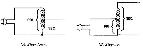
Fig. 12. Autotransformers. (A) Step-down. (B) Step-up.
AUTOTRANSFORMERS
The aut otransformer is an exception to the rule that there is no direct metallic connection between primary and secondary. In the aut otransformer, the same turns are used for both windings.
If all of the turns are used as the primary, as in Fig. 12A, the autotransformer has a step-down ratio. A step-up autotransformer is shown in Fig. 12B. Here, the turns below the tap serve as the primary, and the entire winding is used as the secondary. The autotransformer is sometimes constructed with several fixed taps or a movable tap to permit variation of the secondary voltage.
FLYBACK TRANSFORMER
The fly back transformer employed in tv receivers utilizes aut otransformer action. As indicated in Fig. 4-9, the portion of the winding between the tap and B supply serves as the primary.
This primary is connected into the plate circuit of the horizontal output tube. The entire winding functions as the secondary and is connected to the high-voltage rectifier tube. Because the horizontal-output tube is excited by a sawtooth input, the primary current alternately builds up and decreases. The decrease causes the magnetic field of the primary winding to collapse. This collapsing field cuts across the entire winding, inducing thousands of volts. Additional windings on the flyback transformer supply heater power to the rectifier tube and couple the sawtooth to the horizontal-delection coils.