Model railways are probably the second most popular use for soldering. In this Section 1 will cover soldering of all gauges from N to O and all aspects from trackwork to white metal.
Equipment Recommendations Soldering Irons
All types of gas irons would be suitable for most applications especially for N and 00 gauge although If would be doubtful as to their use in O-gauge, unless the flame head is used, other than for electrical wiring. They would not be suitable for wiring to O-gauge track.
Rechargeable irons would only be suitable for soldering electronics and other small work around the layout. They are unlikely to be suitable for soldering to track in any gauge.
As they would therefore have only a very limited use, they would not be very suitable for this application.
With electric types, obviously different sizes will be required for different gauges.
Voltage
Most people will use 240 volt soldering irons throughout their layout, although 12 volts is also a possibility. A word of warning when selecting a 12 volt soldering iron for this use.
As I have mentioned previously, it is the current rating (amps) that is critical with 12 volts. Before buying a 12 volt soldering iron check the capacity or output of the power supply that you intend to use to power it.
If you are going to use your controller then it is important that you check the capacity (amps) of the single output you are going to use, not the overall capacity of the controller. It is my experience that most controllers, whilst having a total capacity of 2.5 amps, actually have several outputs, the biggest of which is usually only 1 amp. This could power no more than a 12 watt soldering iron. Anything bigger will need its own separate power supply costing a large amount of money, so it is best to avoid 12 volts for this application.
Wattage
My recommendations are as follows:
N Gauge Up to 18 watts for all work, with bits up to 4.5mm for trackwork.
25 to 50 watt irons will be required for making models in brass, nickel silver, copper or white metal.
00 Gauge
Up to 25 watts for all work with bits up to 6mm for trackwork.
25 to 70 watt irons will be needed for brass, nickel silver, copper or white metal.
O Gauge
25 to 70 watts for most work with bits up to 12.5mm for trackwork.
Over 100 watts for brass, copper, nickel silver and white metal.
The above recommendations are for average use and some of the sizes can be varied depending on the work to be done.
Remember that it is better to have a larger soldering iron with a smaller bit fitted than a small soldering iron with a big bit.
Solder Types
Soldering for model railways will be similar to that of electronics so for most applications the same solders can be recommended. At the same time you should not choose a solder that is too thick, as previously explained.
Suitable sizes are:
N & 00 Gauge Up to 20 swg.
O Gauge
Up to 20 swg for wiring, etc., and up to 16 swg for track-work.
Fluxes and Tools
An earlier Section dealt with the different fluxes. For some reason there is a glut of unidentifiable bottles available in the model railway business. Take note of the warnings already given in the flux Section.
Tools again will be the same as recommended in the electronics section.
Starting to Solder
It should now be obvious that the majority of soldering around a model railway is the same as for electronics and therefore the same technique applies. The main differences will be when soldering to the track or when actually building the models.
Soldering Track
When soldering to the track there are several areas to keep in mind. Firstly, never solder on the inside of the track, however tempting this may be. If you do, the train will almost certainly be derailed due to the restriction of the gauge.
Secondly, never allow the solder to flow onto the top face of the track, this again will cause the train to be derailed.
Finally, while British Rail can get away with continuous welded rail, it is totally impractical to do this with model railways. The British Rail technique is to form a weld almost by recasting that part of the joint. If you try to emulate this you will surely fail due to the different expansion factors of the rail and the solder. If you are laying track outdoors, it is wise to use good quality fishplates and then solder wires across the joints on the outsides of the two rails. Then, if oxidization prevents good electrical conduction across the fishplate. it will be maintained through the wires.
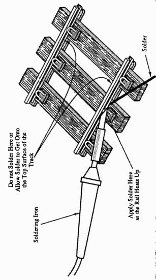
Fig. 10.1 Tinning the rail ---- Do not Solder Here or Allow Solder to Get
Onto the Top Surface of the Track
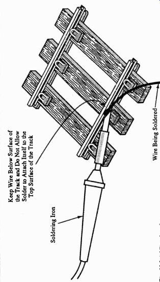
Fig. 10.2 Adding the wire --- Keep Wire Below Surface of the Track and Do
Not Allow Solder to Attach Itself to the Top Surface of the Track
The procedure for soldering to the track is as follows, remembering that a much bigger soldering iron bit will be required due to the mass of metal in the rail:
(i) Tin the wires as previously explained.
(ii) Apply the soldering iron bit to the outside of the rail and allow the rail to heat up (Figure 10.1).
(iii) Apply pre -fluxed solder to the rail, not to the soldering bit. If you do it this way, the solder will only melt when the rail is at the correct temperature. As previously mentioned, do not allow the solder to get onto the top face of the rail.
(iv) Lay the tinned wire along the tinned rail, but before soldering it to the rail check that the position of the wire will not foul the track. Apply the soldering iron bit to the wire (Figure 10.2) and watch the solder melt on both the wire and the track. This should happen fairly quickly. If it does not then you should be using a bigger soldering iron or bit.
(v) Remove the soldering iron and hold or support the wire very steadily until the solder has hardened, at which time you should have successfully completed the joint.
There are several problems that you may encounter when soldering areas like track. As most track is now on plastic sleepers there is a danger that leaving the soldering iron on the rail for too long will almost certainly melt the sleepers. This will be more likely if you use a soldering iron bit that is too small, as the rail will take much longer to heat up to the required temperature. Secondly, if you use bare solid wire to solder across the track joint, it is more than possible that when soldering the second end of the wire, the first joint will melt and become dry. I suggest that PVC -coated stranded wire be used for bridging the joints. It will not only prevent so much heat travel but will also be more flexible and absorb the obvious vibration from the trains much better.
Soldering of Larger Parts
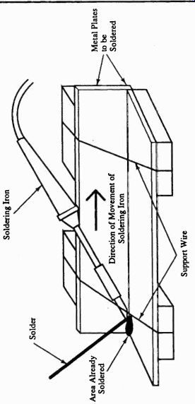
Fig. 10.3 Soldering larger items
As has been mentioned several times previously, larger brass, nickel silver and copper parts need a much larger soldering iron and bit to ensure good soldering. The reason for this is that they dissipate heat very quickly, which is why manufacturers of soldering equipment use copper for their soldering iron bits. Whilst this works very much in the favor of the soldering iron bit, it unfortunately works against the modeler due to the heat being dissipated away from the joint very quickly. The other problem is that of joints that have already been made coming apart because the heat from the soldering iron has travelled beyond the work area. When soldering larger items (boilers, frames, coach sides, etc.) it is wise to get them mechanically set up and supported before starting to solder. Even for N Gauge, you will need a fairly large soldering bit for these materials, probably as large as 6mm. You will probably think that this is too large for the area to solder but in my experience anything smaller will cause the inevitable dry joint. Remember that the faster you can complete the joint, the less distance the heat will flow.
The technique for soldering larger areas of these materials is as follows:
(i) Thoroughly clean the areas to be soldered. If possible smooth out any cut or file marks with a fine abrasive like emery cloth, etc. When cleaned, do not touch the areas with your fingers. The grease from your fingers will repel the solder and again cause a dry joint.
(ii) The parts to be soldered should be mechanically set up before soldering, either by wiring them in place or by supporting them in some other way. I have emphasized previously the heat dissipation factor of these materials. You will probably not be able to hold the parts in place with your fingers long enough for the solder to solidify, due to the heat travel. This will mean that if the joint is not otherwise supported you will inevitably have to let go of the material before the joint is complete to stop burning yourself.
(iii) Once the areas to be soldered are set up, make sure that the soldering iron can be applied to the joint without difficulty.
(iv) If you need to use additional flux then carefully apply this with a paint brush only where it is needed.
Again, all these materials should require only an inert flux. If you use an active flux then you will have to scrub the excess flux off after you have completed the joint.
(v) Apply the soldering iron to the parts to be joined with a bias to the tinned area of the soldering hen bit touching the larger piece of material. Remember that for successful soldering both parts must reach the required temperature.
(vi) Apply the solder to the material, not the soldering iron bit (Figure 10.3). You should test the area of material slightly away from the joint (approximately 0.5mm) ensuring that the solder melts at that point.
Run the solder into the joint and for long runs (e.g. coach sides or boilers) slowly move the soldering iron away from the area already soldered, running the solder after the soldering iron and applying the solder to the material and not the soldering iron. If you have difficulty with this operation then either the soldering iron or the soldering iron bit are not large enough. This means that you will not successfully complete this operation unless you increase the size of one or other item, regardless of the size of the work to be soldered.
(vii) Finish off by removing the soldering iron and running the solder up to the end of the joint.
(viii) Filially, and most importantly, leave the whole area to cool for several minutes. Due to the heat dissipation, a large area of the material will have been heated and will take some time to cool right down.
If you are going to solder several parts together, like for example coach bodies, then these should be pre-assembled and supported to prevent one part falling off when trying to solder another.
Another tip is to use standard solder for the major seams on the larger parts and a lower melting point solder for all the fittings. Remember that no matter how small one of the parts to be soldered may be, it is the larger part that it is most important to get to the right temperature. Obviously, if the same solder that has been used for the main body is used for the fittings, then it is possible to melt the solder on the main body seams. For the same reason, I would not recommend the soldering of white metal parts onto these materials, bearing in mind that, as these materials retain their heat for a long time, it is more than likely that the white metal parts will melt.
Finally, I would reiterate the warning that if you have used active flux, any excess will have to be scrubbed off, so avoid its use if at all possible.