The first FM antenna an audiophile usually comes into contact with is the ribbon dipole packed with most FM tuners and receivers, an antenna that is adequate for non-critical applications in high-signal strength areas. However, since the theme of this series of articles is quality FM antenna systems, the ribbon dipole will be relegated to the carton and the discussion of outdoor antennas will commence.

Omnidirectional Antennas
Omnidirectional antennas pick up signals equally well in all directions without the need of a rotator. Although high-gain omnis are possible, with few exceptions the only omnis readily available are the types shown in Figs. 1 and 4. Both of these antennas are variations on the simple folded dipole.
The Channel Master 4405 shown in Fig. 1 is simply a folded dipole bent into an S-shape to convert the dipole's "figure eight" horizontal-plane polar pattern (Fig. 2) into an approximation of a circular pattern (Fig. 3). The resulting antenna has a gain of about -1 dB relative to a /-wave dipole. This type of omni is sold by Winegard (FR-1), JFD Electronics (AFM450), Kay Townes (FMOD-G), Gavin (FMS), and of course Channel Master.
The Lance FMO shown in Fig. 4 consists of two folded dipoles arranged at right angles to each other and t connected by a 1/4-wave phasing harness. This yields a pattern somewhat like that shown in Fig. 5. This type of omni, often called a "turnstile" antenna, has less gain than a 1/2-wave very popular antenna is also sold by Winegard (FM-3T), S&A Electronics (WCF-5), Antenna Corp. of America (AC-103), Kay Townes (FMND-1G), Gavin (FM-7), Jerrold (C677M), RMS Electronics (F-3), Channel Master (4403), and Antennacraft (GFMSS). Antennacraft also makes the G2FMSS, which consists of two vertically stacked turnstiles to achieve a few dB more gain and vertical-plane discrimination.
This means that it has minimal pickup of noise and multipath signals originating above and below it.
When properly located and installed, one of these antennas and some 300-ohm twin leads comprise a very satisfactory antenna system for a large percentage of FM enthusiasts.
The popularity of these antennas is due to the fact that when properly located and installed they provide a good S/N ratio for decent reception in metropolitan and suburban areas, are small and lightweight, low priced, easy to mount, and require no operation (rotation) in use. Their chief disadvantage is they afford no protection against multipath and noise pickup in either the horizontal or vertical planes.
A possible disadvantage is low gain, although as you will see in a later issue this can be an advantage in some situations.
High-Gain Directional Antennas.
A high-gain antenna is needed when a distant station must be received with adequate quieting or when one antenna must drive a number of tuners. A high-gain antenna may also be needed in strong-signal areas, not because of its high gain, but because of the directionality that accompanies high gain.
Directionality (narrow beamwidth and high front-to-back ratio), is the best countermeasure for multipath distortion and various types of r.f. interference. The idea is that a highly directional antenna will pick up lots of signal in the direction it is aimed, but very little signal in other directions (where, presumably, the r.f. interference or multipath is coming from). These directional characteristics also permit listening to a distant station on the same frequency as a nearby (stronger) station. Naturally, these benefits are obtainable only if the desired station lies on a different bearing (direction) from the undesired stations or interference signals. Further discussion of this aspect of directional antennas continues in the section on reception problems at the end of this series of articles.

Fig. 1--The Channel Master 4405 antenna is a folded dipole bent into an "S
shape."

Fig. 2--Polar pattern of a folded dipole.

Fig. 3--The polar pattern of an S dipole.
A very common type of directional antenna is a 3- to 5-element yagi (or beam) antenna. These usually consist of a folded dipole with reflector, and one or more directors (Fig. 6). The reflector and directors change the bidirectional (figure eight) pattern of the dipole to an essentially unidirectional (single main lobe) pattern, like that shown in Fig. 7. Generally, the greater the number of directors, the narrower the beamwidth and the higher the gain of the antenna (at certain frequencies). The parenthetical phrase indicates the "catch"; this type of antenna is capable of high gain and narrow beam width over a portion of the FM band, but cannot provide consistent performance over the full FM band. Still, if cost is a factor, these simple yagis can be quite useful in all but the most critical situations. Even a very simple yagi will provide better S/N and multipath performance than an omni.
The vertical-plane pattern of a small yagi is such that signals above and below the antenna are rejected, as well as those lying along azimuths not covered by the main lobe.
The very best directional antennas are those built to the log-periodic formula, which may be either pure logs or logs with directors. The characteristics that qualify this type of antenna as "best" include high absolute gain, excellent gain flatness across the entire FM band, excellent impedance match (VSWR) across the FM band, and nearly constant polar patterns at any frequency in the band. As you may conclude, the matter of consistent performance across the entire FM band is essentially what sets log periodics apart from the simple yagis.
A small but high-performance log periodic is the Winegard CH-6060 shown in Fig. 8. This ruggedly built antenna has less than 0.4 dB gain variation and only 7° beamwidth variation across the entire FM band, producing about 8 1/2 dB gain with just a 60-inch boom length. A weatherproof housing on this antenna encloses a cartridge offering a choice of 300- or 75-ohm output impedance, so it can feed coaxial cable directly, without the need of an external antenna balun. As you can see from its polar patterns (Fig. 9), it has excellent front-to-back (F/B) ratio (20 dB minimum) and deep side nulls, with a beamwidth of 63-70°. A much larger version, the CH-6065, offers 1 to 2.4 dB more gain, and narrower beamwidth.
Jerrold's QFM-9 (Fig. 10) is a longer antenna (101 inches) costing about the same as the CH-6060. The QFM-9 has slightly less gain (7 dB average), but unusually narrow beamwidth and the same excellent F/B ratio and deep side nulls. The beamwidth of the QFM-9 is only 56° over most of the band, narrowing to 49° at the upper end. This very narrow beamwidth at 108 MHz can be used to advantage in combating CB harmonic interference, as you will see in a future issue. (Note: All antenna gain figures in this article are from their respective manufacturer.
Because of the many complex factors involved in determining absolute antenna gain, the gains claimed for antennas not measured at the same time on the same test range should not be compared without considering that an error of up to 2 dB between antennas is not unusual.)

Fig. 4--The Lance FMO turnstile antenna consists of two folded dipoles arranged
at right angles to each other.

Fig. 5--Polar pattern of the turnstile antenna.
Factors that might be considered disadvantages of log periodics and long yagis are size, weight, and inconvenience. High gain and directionality' are achieved at the cost of great size; antennas such as the Winegard CH-6065 can be over 140 inches long! Aside from the aspect of something this size above your dream cottage, large size also means lots of bucks, both for the antenna and a secure mount. Arid, except for cases where only a single station is within reception range or where all stations lie in the same direction, these antennas must be repositioned (via an antenna rotator) each time you listen to a station in a different direction from the previous one. Here the really good antennas extract the maximum in inconvenience; the very large and directional antennas must be positioned more accurately than smaller antennas with wider beam-widths. (There is no free lunch.)

Fig. 6--A typical 5-element yagi antenna.

Fig. 7--Undirectional pattern of a typical yagi antenna.

Fig. 8--The Winegard CH-6060 high-performance, log periodic antenna.

Fig. 9--Polar patterns for two Winegard log periodic antennas. The CH-6065
(top) has a narrower directional pattern than the CH-6060 (bottom).
Using Your TV Antenna For FM Reception.
Many people who desire a moderate-gain directional FM antenna do not wish to erect a separate antenna and rotator when they already have a large and rotatable TV antenna on their roof. This can be a sound idea with the right antenna-or a terrible idea with the wrong one.
Some TV antennas are designed to provide low-band frequency coverage that holds up well to 108 MHz just as the antenna comes out of its carton.
Other antennas are designed to block FM reception as shipped, but can be modified to receive FM at full gain.
Still other antennas are designed with frequency coverage that falls off rapidly after 88 MHz, and cannot be readily altered for good FM reception.
The Jerrold VU-932S (Fig. 11) is an outstanding example of an all-channel antenna that provides excellent FM performance as shipped. As shown in the VU-932S gain chart in Fig. 12, this compact antenna will provide 3 to 4 dB gain over the full FM band. Since this antenna is also a superb TV antenna (whose performance was verified by the author in competitive measurements), it is highly recommended as an "everything" antenna for metropolitan and suburban areas. At this point I might mention that the VU-9325's performance is not typical of most TV antennas claiming FM coverage. The FM performance of most TV antennas falls off as shown by the center gain chart in Fig. 12. However, since a fair amount of directionality remains even at the high end of the FM band, antennas of this type are usually satisfactory for strong-signal areas.

Fig. 10--The Jerrold QFM-9 high-performance log periodic antenna with an
unusually narrow beamwidth.

Fig. 11--Jerrold Electronics VU-932S all-channel antenna.

Fig. 12--FM gain characteristics of several TV antennas. The Jerrold VU
934S curves (right) show TV and FM performance before (solid line) and after
(dotted line) modification.
The Jerrold VU-9345 is a larger version of the antenna just mentioned. It also offers superb performance, but it must be modified per the manufacturer's instructions to function on FM. This antenna is an excellent example of an antenna designed to block FM signals as shipped, but which can be easily modified (by snapping off the FM control elements) to provide superb FM gain. The gain curves at the right of Fig. 12 show the VU-934s's performance before and after modification. The solid line is for the antenna as shipped; there is a huge "hole" in the response after 90 MHz and in this condition it will perform terribly on FM. The dashed line shows the antenna's gain characteristics after the FM control elements are snapped off. Now the VU9345 has extremely flat gain over the full FM band. In fact, the FM performance of this antenna approaches that of an 8-element log periodic! This is the ideal TV/FM antenna for the far suburbs.
When signals of all kinds are provided by one antenna, a device called a band separator must be used at the bottom end of the transmission line to direct the FM signals to the FM tuner and TV signals to the TV set. With this device most of the signal in each frequency band is automatically applied to the proper receiver. Quite a few TV accessory manufacturers offer three way band separators that provide VHF, UHF, and FM outputs from a single output from a single input. They are available in both 300and 75-ohms input impedance and always have 300 ohms output impedance. (In an all coax system, a balun can be connected to the FM output terminals of the band separator.) The Jerrold FS-1314-FM (shown in Fig. 13) is included with the VU-series antennas mentioned in the preceding paragraphs.
Unfortunately, there is a serious fault in the band-separator technique.
There is no frequency separation between TV channel 6 and the bottom of the FM band, so even a super-sharp filter network (not possible at consumer prices) will attenuate 88 to 90 MHz FM signals in the FM output and channel 6 in the TV output. The solution is to not use a band separator, but to manually switch the entire antenna signal to the FM tuner or TV set (See Fig. 14). Naturally, both entertainment devices cannot be used simultaneously with this technique. The Jerrold DCS is a superb 75-ohm cable switch at a reasonable cost. If the FM stations are so strong as to interfere with your TV reception, you can insert a Winegard T-FM7 FM band-stop filter in the cable going to the TV set.

Fig. 13--Typical VHF/UHF/FM band separator.
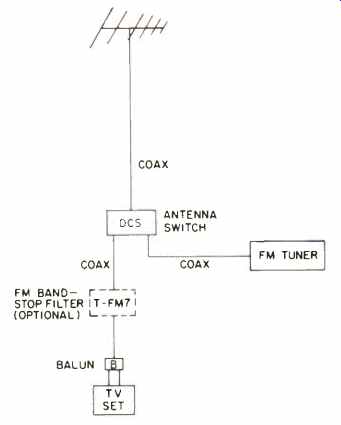
Fig. 14--Manual switching technique to direct the entire antenna output
to either the FM tuner or the TV set.
Where to Mount the Antenna
Advice on where to mount an FM antenna invariably includes sure-fire phrases like "as high as possible" and "in the clear." While these are quite true, attempting to achieve "as high as possible" could involve an expensive
and sometimes prohibited tower, while "in the clear" could require you to move from some locations! For most of us, the selection of a place to mount an FM antenna is limited to finding the best place on our residence to erect a 10-foot mast. The lucky will live in a one-family house amid a sea of one family houses or in the highest apartment house in the area. The unlucky will have a small home right next to an apartment or water tower. This latter group can only pray that some orientation of their high F/B ratio log periodic will yield a sufficiently strong signal that is reasonable free of multipath effects.
My advice is actually on where not to mount your antenna. Do not mount it close to a TV antenna; the proximity of another antenna operating in roughly the same frequency range will disturb the directional characteristics of each antenna, thus increasing the likelihood of multipath pickup.
Similarly, never mount the FM antenna on the same mast as the TV antenna; you cannot get sufficient separation with simple masting to allow this.
Don't use too short a mast; stick with the standard 10-foot mast for omnis and small logs, and a well-guyed 20 foot mast for large log-periodics. Don't put the mast on the side of your house adjacent to a heavily-trafficked road if you want low-noise, weak-station reception. Don't mount any antenna, particularly one on a high mast, anywhere near power lines. Many people have been killed by masts tipping over into power lines during installation.
-----------
Manufacturer's Directory
Antennacraft
P.O. Box 1005, Burlington, IA 52601
Channel Master
Ellenville, NY 12428
Jerrold Electronics
P.O. Box 487, Hatboro, PA 19040
Lance Industries
P.O. Box 4156, Sylmar, CA 91342
Winegard Co.
3000 Kirkwood St., Burlington, IA 52601
-----------
(Source: Audio magazine, Jan. 1978; Michael J. Salvatti)
Next: Antennas Part II--Transmission Lines & Signal Distribution (Feb. 1978)
Also see:
FM Specifications Revisited by Leonard Feldman (April 1978)
Audioprism 7500 Indoor FM Antenna (Dec. 1989)
= = = =