(part 1)

THE IDEAL TRANSMISSION LINE
Something has to connect the antenna to the tuner, so after selecting your antenna you must select the transmission line. The basic choice is between twinlead and coaxial cable.
Twinlead must be installed so it is held several inches from metal objects, does not run parallel to other wires or metal pipes, and does not come closer than one-inch to nonmetallic structures. Coaxial cable can be taped to the antenna mast, run along drain pipes and rain gutters, through and between walls, etc. Twinlead as commonly installed is susceptible to picking up extraneous signals, such as CB interference and impulse noise. Coaxial cable (particularly the foil-shield variety) is virtually immune to r.f. pickup. The low line losses generally attributed to twinlead are obtainable only when the line is new, dry, and perfectly installed. Wet standard twin lead has far greater loss than even ordinary coax, and the impedance irregularities and other aberrations introduced by practical installation requirements increase the line loss of twinlead in any weather. Coaxial cable, on the other hand, has the same loss regardless of weather or surroundings.
Table 1 shows the price/loss relationships between the various types of twinlead and coaxial cables. (For valid price comparisons, only Belden cables are listed in this table.) Notice that every type of coax has lower losses than wet standard twinlead. Shielded twinlead (Belden 8290) is not affected by weather or surroundings, but costs twice as much as coax (Belden 9283) with the same loss figures. The RG6type coax being compared against the high-performance shielded twinlead also has the advantages of far lower wind resistance and high flexibility.
A final advantage of coax: Most high performance signal distribution components (which will be covered later) are made only in 75-ohm impedance models. Clearly, coaxial cable is the ideal transmission line for most FM installations regardless of signal strength.
Coaxial Cable
Nearly any standard (RG59U type) coax is a big improvement over most twinlead, but the newer foam-dielectric cables are preferred because they have even lower losses. Foam-dielectric cables with copper-braid shields (upper cable in Fig. 1) are sold in precut lengths with connectors attached and are widely available in electronic-parts stores and from audio dealers. However, if you want the very best in terms of electric field shielding (for absolute minimum noise pickup), use cable with an aluminized-mylar foil shield and aluminum-braid covering (lower cable in Fig. 1). Although somewhat "rarer" in consumer outlets, this cable is actually less costly than copper-braid coax (Belden 8241 for example). Recommended RG59U-sized foil-shield cables are Belden 9275 and 9282, Jerrold CAC-59, and Winegard CL-2700. It is very easy to install F connectors on this type of cable.
However, if you do not want to bother with this easy job, you can obtain the Winegard CX-series of cables. These are available in precut 25, 50, 75, and 100-foot lengths with connectors installed! This cable (Fig. 2), like the others just mentioned, has a No. 20 inner conductor and foam dielectric, so losses are quite low.
If the transmission line is very long, and the desired signal is very weak, an RG6-type cable is indicated. This cable is slightly larger in diameter than the RG59U types, but is still small enough for easy consumer installations. It also has a foam dielectric and foil-and braid shield, but has a No. 18 center conductor for lower losses. Recommended cables are Belden 9283, Jerrold CAC-6, and Winegard CL-2800. These cables, and all of those mentioned in the preceding paragraph, were personally tested by the author and found to have better-than-rated performance and excellent mechanical quality.

TABLE 1 Transmission Line Performance & Cost Data *
Twinlead
If a non-rotated antenna is feeding a single tuner, certain types of twinlead are suitable under certain circumstances.
For locations very far from both the FM transmitter and interference sources, and which are also located in very-dry climates (a vacation home in the Arizona desert, for instance), tubular twinlead with No.20 conductors has the potential for delivering maximum signal to the tuner. The round cross-section of this line holds dust, pollutants, and moisture away from the most intense part of the electric field, thus minimizing dielectric losses. I recommend Belden 8275 (Fig.3) because it is available in precut lengths of 50, 75, and 100 feet with connectors installed, and is filled with foam to keep dirt and occasional moisture from entering the cable ends.
Its round cross-section gives it less wind resistance and better electrical performance after weathering than the "foam-filled" flat twinlead sold by many manufacturers.
In week-signal areas subject to frequent rain and/or interference, low loss shielded twinlead is ideal. Belden 8290 (which has losses comparable to RG6-sized coax) becomes cost effective at lengths of 50 feet and under, since baluns need not be purchased.
For strong-signal areas, Belden 9090 is ideal; it is cost effective for lengths of 75 feet and under. Because of the foil shield, these lines have nearly as much immunity to electric fields as foil-and braid coax; because they are balanced lines which cannot be unbalanced by proximity effects they also have high immunity to the magnetic-field component of radiated interference.
Both the 8290 and 9090 are available at consumer outlets in precut lengths of 50, 75, and 100 feet with terminals installed.
Connecting the Cable
Most high-quality receivers of recent manufacture have a 75-ohm input connector. In this case, all that is needed is to attach an F-connector to the cable end and screw it on the receiver. If your receiver is either a low-cost or older model, the only input terminals will most likely be 300 ohms (balanced input). In this case, an input transformer is required. This device, popularly called a "balun," performs both the unbalanced-to-balanced conversion, and the required impedance transformation (75 to 300 ohms). These devices (Fig. 4) are low-cost and available at nearly any electronics parts store. Nearly any model will work satisfactorily for FM, although the very best indoor baluns are the RMS Electronics MA-730B, Sony EAC-20W, and Channel Master 7281. These baluns have losses below 0.5 dB and an SWR below 1.2 over the FM band.
Since nearly all FM antennas are designed to feed 300-ohm balanced line, a balun is also required at the antenna. Here the choice of baluns is much more critical. Since the antenna balun is exposed to the elements (pun intentional), the balun must obviously be waterproof. Moreover, it must also be physically compatible with the terminals of the FM antenna you select. Some antennas have widely spaced terminals or have an obstruction between the terminals. The only type of balun capable of interfacing with any FM antenna made is one having long (4-inch) leads of No. 18 solid-conductor wire at its 300-ohm end. Suitable baluns are the RMS Electronics ATR-375, Lafayette 40347, and Channel Master 0090. All of these baluns have low loss (0.4-0.7 dB) over the FM band and are encapsulated in plastic and supplied with a rubber boot to cover the cable connection (see Fig. 5). The rubber boot supplied with Winegard CX-series of prefabricated cables also fits these baluns.
If a Jerrold antenna (QFM-9 or VU series) is used, their STO-82 balun can be used. But this superb outdoor balun will only mount on Jerrold antennas.
Operating Several Tuners
From One Antenna In many locations the desired FM signal levels are many times higher than needed for high-quieting reception. In this circumstance, one antenna can operate several tuners, providing the proper devices are used to divide the signal while maintaining high isolation between the tuners and impedance matching throughout the system. There are two ways of doing this, directional couplers and splitters.

Fig. 1--Typical standard coaxial cable with copper-braid shield at top.
The foil-shield coaxial cable with aluminum over-braid is at bottom.

Fig. 2--Winegard CX-series prefabricated cable is available in lengths of
25, 50, 75, and 100 feet.

Fig. 3--Belden 8275 tubular twinlead.

Fig. 4--Quality indoor baluns.

Fig. 5--Outdoor baluns.

Fig 6--Series connection of FM tuners by means of single-tap directional
couplers.
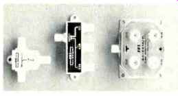
Fig. 7--One-, two-, and four-tap directional couplers.

Fig. 8--Application diagram of a four tap directional coupler.

Fig. 9--Four-way and two-way splitters.

TABLE 2--Performance Characteristics of RMS Directional Couplers
Directional Couplers
When the signal strength is extremely high, the best way is with directional couplers. These devices are simply connected in series along the line distributing the signal (Fig. 6). A 75 ohm terminating resistor connected to the output port of the last coupler in the line completes the system. Impedances remain matched throughout the system even if a tuner is disconnected from a tap (tuner output port). Another unique feature of a directional coupler is that the signal loss in the reverse direction (called isolation) is very much higher than the signal loss in the forward direction (called tap attenuation). This is shown in Table 2.
Hence, oscillator radiation from one tuner cannot get into the distribution system in sufficient strength to cause interference with the other tuners.
Remember, a receiver tuned to 90 MHz is generating a 100.7 MHz oscillator signal. Although modern receivers have very little leakage of their oscillator radiation into their antenna terminals, enough may get out to cause trouble in some circumstances.
Directional couplers are available with 1, 2, or 4 taps (see Fig. 7). Depending on where the antenna downlead enters the building and the layout of the rooms, it may be more convenient to use a multitap directional coupler as shown in Fig. 8, rather than the series technique of Fig. 6.
Each series of directional couplers offers several different values of tap attenuation. This allows the system designer to compensate for cable losses from one end of the distribution system to the other. For example, if a 100-foot length of solid-dielectric RG59U cable is used between each tap, the values shown in Fig. 6 will provide approximately equal signal to each tuner.
Splitters
A signal-distribution system using directional couplers can be quite expensive, since one directional coupler is needed for each tuner when the series technique of Fig. 6 is used. A multiple-tap directional coupler will reduce the system cost somewhat, but the high-level signal requirement of the directional coupler remains.
A rather inexpensive technique, and one better suited to moderate signal levels, uses a signal splitter (Fig. 9). These devices operate with far lower signal loss to each tuner since they simply divide the signal into 2, 3, or 4 equal parts (Fig. 10). The disadvantage of the signal splitter is that the isolation between tuners is net as dependably good as when directional couplers are used; to achieve maximum isolation each splitter output must be kept terminated. If a splitter output is not properly terminated, reflections will result that can affect every part of the system with effects similar to that of multipath.
If the signal level is high (as in metropolitan areas), a splitter offers a third alternative to the methods described last issue for operating TV sets and FM tuners from the same TV/FM antenna. The splitter would simply replace the DCS cable switch in Fig. 1-14, eliminating the need for manual switching.
Some excellent 75-ohm splitters with 2, 3, and 4 outputs are listed in Table 3.
The performance data in this table are not taken from manufacturers' literature, but are the results of measurements made by the author at 100 MHz.
For those diehards who insist on using twinlead, a good and readily-available 300-ohm splitter (the RMS Electronics C-2UV) is included. Notice however, that the isolation of this splitter (the best 300-ohm unit available) is nowhere near that of the 75-ohm splitters.

TABLE 3 Signal-Splitter Characteristics

Fig. 10--Application of a two-output signal splitter.
MANUFACTURER'S DIRECTORY
If you cannot purchase the desired signal-distribution component from your local electronics supply store, write to the manufacturer at the address below for ordering information:
Channel Master
Ellenville, NY 12428
Belden Corp
Box 1331, Richmond, IN 47374
Jerrold Electronics
Box 487 Hatboro PA 19040
Lafayette Radio Electronics
111 Jericho Turnpike, Syosset NY 11791
RMS Electronics
50 Antin PI., Bronx NY 10462
Winegard Co.
3000 Kirkwood St., Burlington Iowa 52601
-----------
(Source: Audio magazine, Feb. 1978; Michael J. Salvatti)
= = = =