
by LEONARD FELDMAN
A number of years ago, the Editors of Audio asked me to test and evaluate a half dozen or so of then-popular outdoor FM antennas. To this day, my neighbors look at me with raised eyebrows, no doubt convinced that I am either slightly eccentric or awfully hard to please: During that testing period I hired the services of an antenna installer who would climb up to my chimney top every two or three days, remove the FM antenna that had been painstakingly mounted there a few days before, and proceed to mount a new one in its place. This went on for the better part of a whole month!
When the present Editor asked me to do another survey and test of FM antennas, my first reaction was, "Thanks, but no thanks!" Cold weather was approaching, and I wasn't ready for more of those neighborly stares. Happily, I learned that the actual testing, this time, would be done in Stamford, Connecticut, by the prestigious CBS Technology Center and under the supervision of Frank Barr, Manager of their Product Evaluation Laboratory. My job would simply be to interpret and explain the data. Having worked with Frank Barr on a variety of other test projects, I agreed.
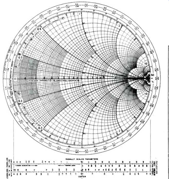
----The reference Smith chart shows the relative predominance of
resistive, capacitive and inductive components in an antenna's impedance. Resistances
fall on the horizontal line, inductive reactances above and capacitive reactances
below.
Testing outdoor antennas meaningfully is not simple, as I learned from discussions with Mr. Barr. Furthermore, as is obvious from the "specifications" listed (and not listed) in Table I, most manufacturers of antennas provide only the most meager data regarding their products; the tester is left on his own to come up with tests and numbers that enable proper evaluation of antenna performance under given reception conditions.
The Test Site and Setup
The test site was the CBS Technology Center, some 35 miles from most of the FM transmitting antennas in mid-Manhattan, New York. A source antenna was mount ed on the roof of the laboratory. The antennas under test were mounted on top of a testing tower approximately 75 feet above ground level and about 400 feet away from the source antenna. The dynamic range of the test facility was in excess of 50 dB. The average radiation uniformity across any given antenna under test was approximately 1 dB. Transmissions of the test signals were done only during the normal vertical blanking period of the nearest TV station in order to prevent interference with any FM or TV station in the vicinity.
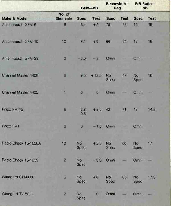
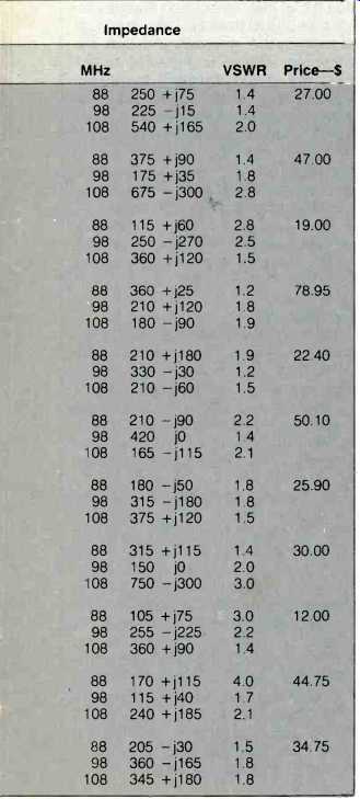
Table I--Manufacturer's specifications and measured test data. A +j value
for impedance represents inductive reactance, while a-j value represents capacitive
reactance. No specs are given by Radio Shack; the balance list impedance at
300 ohms, except for Winegard's CH-6060 which is listed as 75/300 ohms.
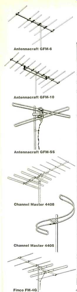
Antennacraft GFM-6 Antennacraft GFM-10 Antennacraft GFM-SS Channel
Master 4408 Channel Master 4405
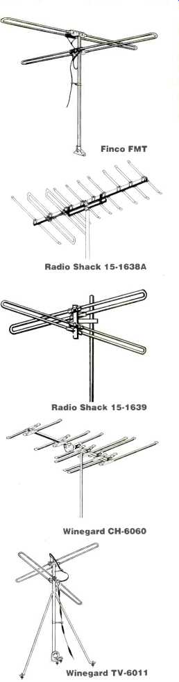
Radio Shack 15.1638A, Radio Shack 15.1639, Winegard CH-6060, Winegard
TV-6011
Antenna Characteristics
As a general rule, when you see an antenna that has many rods or elements, you can assume that it is highly directional. That is, it is more sensitive to signals arriving perpendicular to its active elements than it is to signals coming in from other angles, or even from the opposite direction. Such directionality is desirable in an FM antenna for at least two reasons. First, antennas that are highly directional also have high "gain." Gain, when referring to an FM antenna, must always be related to a standard reference antenna whose gain is arbitrarily said to be 0 dB. In these tests, the reference antenna was a simple, standard half-wave dipole, cut to a length which is resonant at the frequency of the received signal with which it is tested. Rabbit ears and the flat twin-lead antennas provided with FM tuners and receivers are the most common dipoles. Six of the antennas tested are multi-element, directional types, and these would be expected to have gain well above 0 dB. The remaining five are so-called omnidirectional types, and these might be expected to show 0-dB gain values or even slightly negative gain. The measurement of gain was made from the frontal or main lobe (0°) of the polar plots taken for each antenna and reproduced here. For example, a gain of 6 dB as listed in Table I (summary of test data) means that the particular antenna delivers twice the voltage or four times the power (in dBf) compared to a standard half-wave dipole. The higher the gain and directionality of the antenna, the longer and narrower the front lobe becomes.
Directivity and Beamwidth
While antenna gain is certainly an important parameter to be considered in judging an FM antenna, it is assuredly not the only one. The polar patterns plotted by CBS Technology Center for the 11 antennas provide us with other useful information. For the six directional antennas, measurements of beamwidth and front-to-back ratio were also made. Beamwidth is the antenna's front radiation angle, which is defined by the half-power points (-3 dB). If this angle is too great, the antenna is insufficiently directional, and it may have trouble rejecting reflected signals. If the beamwidth is too narrow, you may have trouble locating the precise position that gives the best reception on one station, possibly sacrificing some quality on other stations.
The six highly directional antennas tested are designed to be used in weak signal areas but may also be suited for close-in reception conditions where problems such as multipath reflect ons and co-channel or adjacent channel interference exist.
Omnidirectional antennas, though always much lower in gain and lacking any significant directionality, may still be the best choice in certain situations.
For example, if you live in an area which is relatively free of multipath problems, receives strong signals, but receives them from many points on the compass, a low-cost omnidirectional antenna may suffice. If, on the other hand, you have multipath problems, weak-signal conditions and station signals arriving from many points on the compass, your only solution may be to select a directional antenna and add a powered rotator.
The last characteristic which can be determined from the polar plots is called front-to-back ratio. It is the ratio between the signal gain of the front lobe and the gain of the signal coming in from the rear (180°). Although all antennas also have some lobes to the sides and rear, those with the smallest back lobes are likely to have the best rejection of signals coming from the back of the antenna. This is especially important if you happen to be located between the two transmitters, each off in a different direction.
Antenna Impedance
If you've ever examined the rear panel of an FM tuner or receiver, you have probably seen the notation "300 ohms" next to the two screw terminals to which the antenna down-lead is connected. Many tuners also incorporate coaxial connectors which bear the notation "75 ohms." These numbers refer to the input impedance of the r.f. circuitry of the FM set. Ideally, there should be a perfect match between your antenna, its down-lead or cable, and the input impedance of your FM receiver or tuner. All of the antennas tested for this report have a nominal impedance rating of 300 ohms, with the exception of the Winegard CH-6060. The CH-6060 is basically a 75-ohm unit, but it is supplied with a matching transformer that can be set for either 75 or 300 ohms. If your FM tuner or receiver is equipped only with a 75-ohm input terminal, it is possible to use a 300-to-75 ohm transformer device which, in theory at least, maintains a correct match between the antenna and the circuits to which it is connected.
When a proper match is maintained between antenna and FM tuner, maximum power transfer takes place between the two. In practice, such a perfect match is seldom achieved. The impedance of an antenna is hardly ever exactly its nominal value (300 or 75 ohms), and even if it is, it is not likely that this value will be maintained over the entire tuning range (in this case, from 88 to 108 MHz). Furthermore, an ideal antenna would have an impedance which is purely resistive, whereas in actual practice an antenna's impedance is usually partly resistive and partly reactive (inductive or capacitive).
Mismatches in impedance cause some of the signal energy received to be reflected back up the transmission line, to the antenna. If the antenna is totally resistive, it absorbs this reflected energy. But if, as in most cases, there are reactive components in the antenna's impedance, some of the reflected wave bounces back yet again towards the tuner or receiver. Such reflections can cause various forms of distortion in the received audio program, most of which sound like multi-path distortion.
While deviations from the purely resistive ideal make for a less-than-perfect antenna, performance degradation (even with relatively large mismatches and rather highly reactive components) is not as great as you might think. So, while the a.c. impedances shown in the test results of Table I seem, in many cases, to be far from the "ideal," note that both resistive and reactive components normally vary rather widely over the FM frequency band, and at some frequency the overall impedance may be closer to the ideal value of 300 ohms, and purely resistive at that.
Although Table I lists only the impedances observed at 88, 98, and 108 MHz for the 11 antennas tested, these values were obtained using a display known as a Smith chart. A detailed photostatic view of the Smith chart is shown for reference along with Smith chart 'scope readings for each of the 11 antennas measured. The bright dots in each 'scope photo show the impedance value for the identified frequencies. A purely resistive value will appear as a bright dot along the display's horizontal center line. An impedance dot in the upper hemisphere of the display indicates an inductive reactance. Dots appearing below center indicate the capacitive reactance. An antenna having a purely resistive impedance of exactly 300 ohms would produce a dot lying exactly on the horizontal axis, where the numeral 1.0 is seen in the reference Smith chart.
Note, for example, that the Finco (Finney Co.) FM-4G comes close to this ideal at a frequency of 98 MHz, at least insofar as its being purely resistive.
The Channel Master 4405, at 98 MHz, also comes very close to the ideal value of 300 ohms (resistive) with minimal capacitive reactance which would have negligible effect. In Table I under "Impedance," the first number in each measurement tells the resistive component, while the number following the letter "j" depicts the reactive component. A "+j" means inductive reactance while a "-j" means capacitive reactance.
The Voltage Standing Wave Ratio (VSWR), also tabulated in Table I, is the ratio of the highest and lowest voltages in a transmission line and is a function of the impedance match between the antenna and the FM receiver. Under ideal conditions, the VSWR would have a value of 1.0. All of the FM antennas tested exhibit values greater than 1.0, showing that some portion of the electromagnetic energy is being reflected instead of being delivered with maximum efficiency to the antenna. I should stress that "perfection" in antenna design is never completely achieved, particularly when an antenna has to cover a wide range of frequencies.
Test Results
The results obtained by CBS Technology Center and summarized in Table I pretty well speak for themselves.
Clearly, when it comes to antennas for FM there is no such thing as a single "best" model for everyone, since qualities that are important in a particular geographic location will be less important in another.
The highest gain was exhibited by the Channel Master 4408 (12.5 dB), with the Antennacraft GFM-10, Finco FM-4G and Winegard CH-6060 next in line. Those seeking a narrow-beam-width (highly directional) antenna may also want to choose the Channel Master 4408, though the Radio Shack 151638A, the Antennacraft GFM-10 and the Winegard CH-6060 all did quite well in this regard. If high front-to-back ratio is what you need, the six-element GFM-6 by Antennacraft did very well (a high 19 dB), followed closely by the Winegard CH-6060 and the Radio Shack 15-1638A (17.5 and 17 dB respectively).
As for antennas with "best" impedance characteristics and lowest voltage standing wave ratios, no clear winner emerges since, as I said, these characteristics vary widely with frequency of the signal being received by the particular antenna. I did note that VSWRs for the Channel Master 4408 and 4405, the Finco FMT, and the Winegard TV-6011 did not exceed 2.0 at any of the frequencies at which they were tested.
General Conclusions
Using a good FM antenna is probably the single most significant improvement you can make for good FM reception. As pointed out by the CBS Technology Center, this fact is often overlooked by many, who insist upon using the ribbon-wire dipole supplied by the manufacturers of most tuners and receivers.
The six directional antennas tested were designed to be used in weak signal areas or, as stated earlier, in areas having reception problems attributable to signal reflections. If you are trying to receive very distant signals or plan to use one antenna for more than one set (an arrangement which obviously reduces signal strength available to each set), one of these antennas would be a good choice. Mounting should be on a separate mast, away from other antennas and power lines, and, if need be, an antenna rotator should be used.
The remaining five antennas tested are omnidirectional. Compared with a standard dipole, these units have very little gain and often even a loss. They should only be used in strong signal areas which are free of multipath and r.f. interference. No rotator is needed, and an omnidirectional antenna can generally be mounted on an existing TV antenna mast, although a distance of at least four feet should be maintained between it and any other antenna already on that mast. In addition, any antenna installation should be kept well away from any power line as a safety precaution.
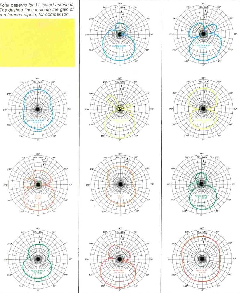
Polar patterns for 11 tested antennas.
The dashed lines indicate the gain of a reference dipole, for comparison.
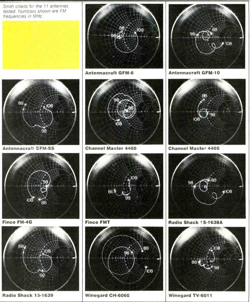
Smith charts for the 11 antennas tested. Numbers shown are FM frequencies
in MHz.
==================
ANTENNA TYPES AND TERMS
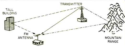
How multipath occurs. Note that the signal being broadcast by the
transmitter will arrive at the home antenna by three different paths.
Antenna performance is always rated relative to the performance of a reference dipole. You may never see such an antenna on a rooftop, but if you did, it would look like a flattened-out Channel Master 4405 or like one of the crossbars on the other omnidirectional antennas shown. Rabbit ears and the flat, twin-lead antennas provided with FM tuners and receivers are the most common dipoles.
A reference dipole's directivity also resembles that of the Channel Master 4405 except that the dipole's figure-8 pattern is narrower, with less side pickup.
Omnidirectional antennas should theoretically be equally sensitive in all directions. In practice, their patterns usually range from the fat figure-8 of the 4405 to the pinched-in circle of the Winegard TV-6011.
Directional antennas come in several types (yagi, log periodic, et al.) which almost invariably consist of several parallel elements, one behind the other.
While they are usually far more sensitive in their forward direction than any other, plots of their directivity usually show some sensitivity to the back or sides.
Directional antennas tend to have more obviously asymmetrical directivity plots, too.
Directivity is needed both to concentrate an antenna's sensitivity in one direction for weak-signal pickup, and td exclude unwanted signals. In fringe areas where the listener lives roughly halfway between two stations sharing the same frequency, such signals may include co-channel interference.
Unwanted stations may also include strong stations on a frequency near that of the desired one, especially if the tuner's selectivity is poor.
Directional antennas are also frequently used to reduce multipath pickup, where the incoming signal is accompanied by signal reflections (see illustration). Since reflections follow longer paths than the direct signal, they are delayed. A mixture of direct and delayed signals can cause distortion on FM, equivalent to "ghosts" on television. A directional antenna can exclude these delayed signals to pick up only the direct signal. In some situations, a directional antenna can be aimed to exclude a direct signal accompanied by several reflections. Instead, it should be aimed to pick up a reflection coming in alone from someplace else.
-Ivan Berger
==============
(adapted from Audio magazine, Jan. 1983)
= = = =
Also see:
The Problem with FM (March 1985)
Antennas FM -- Try a Rhombic FM Antenna (Jan. 1982)