by BERT WHYTE
This column is devoted to "aid and comfort for the audiophile." Every now and then, it is worthwhile to address our attention to equipment other than the major items of amplifiers, loudspeakers, tuners, turntables, and cartridges. Much of this "minor" equipment might be dismissed as gadgets and gizmos, but more often than not these items are amenities and conveniences which not only add to the enjoyment of an audio system, but make a very significant contribution to its overall quality.
Many audiophiles are afflicted with what might best be called "tape-loop trauma." They have acquired so much auxiliary equipment and so many signal processing devices, all of which require high-level inputs and tape-monitor loops, that even the most elaborate preamp/ control centers lack sufficient input capabilities.
Consider that a well-equipped audiophile may own a cassette deck (or two), perhaps a pair of open-reel tape decks, external Dolby and dbx noise-reduction systems (including dbx disc playback), an expander, an equalizer, a time-delay system, an autocorrelator, a click suppressor, a Tate SO decoder, a hologram or audio image enhancer, and Lord knows what else. Up to now, integrating all these devices into a work able, flexible, hum-free system has been a classic exercise in frustration. The smaller interconnect devices, such as those made by Russound, have been helpful, and if you are still into four-channel sound, they make a box to help cope with those problems. However, folks with a knowledge of professional studio practice are well aware that a patch bay and jack system is really the answer to multiple-device and interconnect problems.
However, they've equally been aware of the intimidating lob of soldering and construction such a project entailed, to say nothing of the very considerable initial expense.
A bright young fellow named Orrin Charm had the good sense to recognize this interconnect problem and devised an elegant, truly flexible patch bay system based on professional recording and broadcast studio practices. Charm's Audiovisual Systems Model PB-289G patch bay system is the embodiment of all his ideas on this subject. The PB 289G is 19-inch rack-mountable, to EIA standards, or it may be placed on a shelf on four supplied rubber feet. The unit is but 1.7 inches high and 5.5 inches deep, and its chassis is welded steel with a double-anodized black aluminum front panel. The rear panel has 16 color coded two-channel inputs (32 gold plated RCA phono jacks) and 16 two- channel outputs (32 more gold-plated RCA phono jacks). The front panel has 16 stereo inputs and 16 outputs using three-conductor Bantam jacks with gold cross-bar contacts; patch cords are three-conductor Bantam. Plugs and jacks are said to be capable of a minimum life expectancy of 10,000 cycles.
The front panel also has an extra pair of stereo phono jacks for temporary use of external components and a special blue colored corresponding Bantam jack for utilizing these jacks. On the right of the front panel are patch cord jacks labeled "MuIt 1" and "MuIt 2" which in essence function as built-in "Y" connectors to feed a signal to several components simultaneously.
Internally, this patch bay uses a fully shielded printed circuit design with no discrete wiring or active circuitry. There is an ultra-low resistance ground plane on the input board, providing a true single-point ground for prevention of ground loops, crosstalk, and r.f pickup.
All switches, jacks, circuit board inter faces, and other contact surfaces are gold plated.
What is unique about this Audiovisual Systems patch bay is its concept of "programmable normalling." Removing the top cover plate of the patch bay reveals 16 slider-type switches. When the switches are in the " Normal" or in position, the correspondingly numbered outputs are internally connected to the same numbered inputs when no patch cord is inserted. When the switches are in the out position, the rear panel jacks are connected only to their corresponding front panel jacks, and not to each other. With this kind of setup, all of your various components can be plugged into the rear panel jacks, and with the switches in the "Normal" position, no patch cords are necessary for regular system operation. The patch bay can be "programmed" in the sense that when the " Normal" switch on a designated channel is in the out position, you have the option of using equipment which you ordinarily would not use, such as test gear, but which you would like to have avail able. Although all your components are now hooked up to the rear panel and no access to it is necessary in normal operation, what do you do if you want to rear range signal flow among some of the components? The patch cords carry both channels of the stereo signal, so simply by plugging in a patch cord to any output, you have an additional source of that signal, without disturbing the normal connection. Plugging the other end of the cord into any input will disconnect the normal source and substitute the selected output signal. There are many combinations of equipment signal flow possible, and two patch cords can reportedly handle about 95 percent of the patching requirements in a recording system. The front panel's external jacks permit patching in of test equipment for component checking; for example, easy alignment of tape recorders. The PB-289G is designed for un balanced stereo signals but with an accessory balanced bridging box may be used for high-level balanced signals.
The PB-289G is of precision construction with high-quality material used throughout; its price is $795. If you have ever had to contend with a maze of wires and connections in a complex audio system. this patch bay is a godsend. 11 is versatile, flexible, quiet, and hum-free.
For owners of some of the more stark purist-oriented preamplifiers with few in put facilities, the PB-289G can be in valuable.
Bob Fulton of Fulton Musical Indus tries is always coming up with new ideas to maintain or improve the quality of high-fidelity music reproduction.
Whether or not you feel that the various special types of speaker wires have a salutory effect on the sound quality in an audio system, many audiophiles do use such cables. Invariably, these wires are heavier than the usual 16-gauge wire found in most audio systems. Those who favor Fulton Gold speaker wire are faced with something approaching the diameter of garden hose! Now as is well known, many amplifiers and loudspeakers are equipped with banana plugs for interconnection, and these plugs are fervently cursed and condemned by the audiophiles who use the heavier speaker wires for the very simple reason that such plugs can rarely accommodate the larger wires. Even when the fitting is accomplished by some jury-rigged expedient, the sheer weight of the wire often causes the plugs to disconnect - sometimes with catastrophic results.
Bob Fulton has been investigating the problems of banana plugs and believes that even with normal speaker wire they are bad news. He states that because of the thinness of the "leaves" on a banana plug, under typical signal output conditions these leaves cause the plug to vibrate and chatter violently. Fulton re ports there is discrete arcing and wildly fluctuating voltage and noise spikes across the entire frequency bandwidth.
He says that with older banana plugs whose considerable use has resulted in a loss of springiness in the leaves, signal loss can be as much as half a volt.
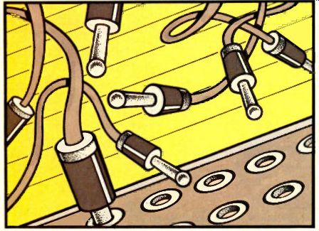
To counteract these anomalies of banana plugs, Bob Fulton has introduced his latest product, the Fulton High Performance Audio Connector. Available in small, medium and large sizes accordingly matched to amplifiers of ascending output power, these are two-piece, high mass, gold-plated, solid copper connectors with special tapered interface plugs that are said to insure maximum contact area and secure fit without arcing. Each plug has what is known as a "Murphy Taper," which fits into its jack receptacle quite easily, and, although there are no threads or machined interlock slots, the plug cannot be dislodged unless rapped sharply on the side of its housing. A threaded screw bolt with an hexagonal head screws into the end of the tapered plug. In use, the speaker wire is fitted with a rugged closed-eye lug and then is connected to the plug by the screw bolt.
Bob Fulton showed me a photograph of the CRT screen of his Crown Badap signal analyzer, which has the ability to show multiple signal traces in various colors. A blue trace at the top of the screen recorded the amplifier output through a banana plug as a very spiky, jagged display. Some 70 dB down at the bottom of the screen was a pink trace, which was virtually a straight line and represented the amplifier output through the new Fulton connector. Bob said this showed its ability for maximum power transfer without being frequency selective. Needless to say, to secure maximum benefit of these Fulton connectors, they should be fitted to both amplifier and loudspeakers. The small, medium, and large connectors require mounting holes of 7/16-inch, 11/16-inch, and 1 inch diameter respectively. They are fit ted with heavy nylon washers and massive nuts, and the back ends of the connectors have the same threaded bolt setup for wire connection as does the tapered input plug. The small, medium, and large Fulton connectors respectively cost $19.95, $29.95, and $49.95. Not only do these connectors make possible the use of the heavy speaker wires, their higher quality power transfer may justify the use and expense of such wire.
The Electro-Clamp Four is a useful voltage clamping device, a solid-state shunting system designed around a semiconductor NASA chose for such purposes. Although electrical service is pretty much taken for granted in this country as steady and reliable, it is subject to voltage transients and harmonic distortion. It is claimed that the average commercial a.c. power circuit receives many transient voltage spikes in excess of 1,000 volts every day. The IEEE re ports that standard 120-volt ac. lines receive transient pulses up to 5,600 volts from a variety of sources including lightning, static electricity, brush-type motors, air conditioning, electrical circuits on furnaces. etc. With more and more audio equipment using microprocessors (especially cassette recorders) and all manner of IC chips, these transient pulses or surges can be a problem.
The transients can cause misreading of logic, falsely trigger semiconductors into conduction, and if you are into home computers of the Radio Shack and Apple variety, they can actually cause loss of data. The cycling of refrigerators and furnaces can cause transients which can create annoying "pops" through your speakers. The Electro-Clamp Four effectively eliminates all these line transients.
Installation is as easy as removing the wall plate from a standard duplex a.c. circuit, plugging the device into place, and fastening it with the center screw.
The Electro-Clamp Four also converts the duplex outlet to four outlets. The device is rated for 15 amps at 125 volts, clamping voltage is 160 V rms, 226 V peak, peak pulse dissipation 6,000 W for 1 mS, and surge rating 500 amps for 1/120 S. Response time is better than 5 nanoseconds. The price of the unit is $39.95, and it is manufactured by CNS Electronics Corp., 41 Sun St., Waltham, Mass. 02154.
So there you have a few interesting and worthwhile pieces of ancillary equipment, one of which may well solve a serious problem for you. Certainly, there are others of this type, and I will mention them from time to time, for they are worthy of our attention, though perhaps not of being reviewed.
-----------
(Adapted from: Audio magazine, 1981; Bert Whyte )
= = = =