1. Chip Components
Surface mount components differ from their TH (thru hole) counterparts in many ways. The constructor should be aware of their likes and dislikes and treat them with due respect if they are to give their best performance. This involves the right choice of component in the first place for a particular application. In this section we will deal with the component classes separately, paying particular attention to their physical appearance and construction so that you will become familiar with them. This will hopefully create a desire to have a go in practice. SMDs are very much smaller than TH components. This is important in terms of electrical performance and is also reflected in the techniques for using SMDs with which we will deal later. The small size is mostly the result of using less packaging material and there is no requirement for bulky lead fixtures. There is therefore less protection between the active element of the component and the outside world. However higher quality materials are used in their manufacture and SMDs are in fact very tough with failure rates lower than conventional devices. The loss of connecting wires results in lower inductance and better RF performance and this is further aided by the shorter distances between components on the PCB. Conversely the stray capacity between components can be higher. The power rating should be kept in mind as there is less radiating surface to disperse heat. In our review we keep a close eye on the physical dimensions. This is important with chip devices as they have to fit on the PCB foot prints. In general there are few problems in translating from TH to SM-based circuits. Let's now review the cast in order of appearance.
2. Chip Resistors
It is fitting that we should start our more detailed description of chip components with the basic building block of all circuits, the humble resistor. Several types of SM resistors have been developed with new additions regularly appearing. Many of these are for military/space and other specialized use and you will never see them except perhaps in surplus equipment. Down here on earth we still have choices to make between types and sizes. Fortunately there is one type which is by far the most popular and you don't need to bother with the rest until you feel the need. I will however give you a resume of the scope of this art should you need something special. For now, the standard resistor which all us SMers have in mind is the Rectangular, size 1206, metal oxide chip.
These are essentially "thick film" leadless devices consisting of a layer of ruthenium oxide resistive material printed on a tiny slab of alumina as a substrate and protected by a glazed coating. Electrical contact is made at each end with a complex composite of platinum, palladium and silver. A nickel barrier layer is included to prevent leaching of the platinum into the solder. This effect was the reason for poor performance of early components where joints became brittle. Chip resistors are now very rugged and reliable and meet the strict solderability standards required for reflow soldering with zero errors. The oxide film is printed a little under value and then trimmed to increase the resistance to specification. This is achieved by cutting a line across it with a high powered laser or air abrasive whilst monitoring its resistance. You can do this yourself by attacking the edge with some fine emery, not recommended by the purists and it's not always reliable but it's our privilege to bend the rules if we can. The structure of a typical rectangular chip resistor is shown in Figure 4. The wrap-around terminals mean that the chips can be mounted face down.
The full range of E96 values are readily available from 1R to 10M in tolerances of 1%, 2% and 5% in this popular format.
You can also get resistors below IR, above 10M and in tighter tolerances, E192 if you need it. Chip resistors are marked with a three-digit EIA numbering system (Electronic Industries Association 1986) where the first two numbers are the value and the final number is the multiplier, i.e. the number of zeros.
A convenient table of resistor codes and values is given in Appendix 2. Zero ohm jumpers, very handy in practice, have the code 000.
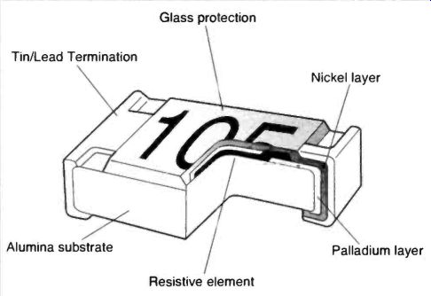
Fig.4 The structure of a thick film chip resistor
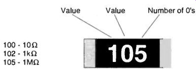
Fig.5 Chip resistor 3-digit code
The selection of resistor size for hand working is more a matter of convenience than power rating. Several sizes are manufactured, the most common being "1206" and "0805", with "0603" and "0402" coming on stream. The "0402" chips are not much bigger than a full stop and are strictly for the fanatics. The largest common size is the 1206 and must be your first choice for hand soldering. The 0805 size is the industry standard for automatic pick and place and is quite manageable for hand working. Typical dimensions for these sizes, in millimeters, are given in Table 1, but they don't relate easily to the size descriptors. This code results from the chip size in inches, because the USA and Japan are very influential in electronics. The first two digits represent the nominal length in inches for example 0.12in and the second two digits the width for example 0.06in, for the "1206" chip size. Metric based codes can also be found, particularly for devices other than resistors, so watch out for this. For example you might, very rarely, find a 1206 chip resistor described as size 3216.
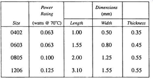
Table 1 Rectangular Chip Resistor Sizes
As examples of the more exotic and rare chips, take two newer types or resistor in the 0603 to 1206 size range with special properties.. These are the thin film types and the metal film types. Thick film resistors are only good for tolerances above 1%. Thin film (nichrome) rectangular chips are high precision devices in the tolerance range 0.1% to 1%. They have good high frequency performance and a wider operating temperature tolerance. Resistor values up to 100k are made at present. The metal film types have tight resistance control with temperature stability of the order of 15ppm, compared to 200ppm for thick film types. E192 values in the range 10R to 22k are made and they have a 4-digit code, 3 value digits plus number of zeros.
Various makes of cylindrical MELF SM resistors have been tagging along right from the beginning of SMT. They are simple adaptions of the leaded types with a circular metal contact at each end. There is not much standardization of sizes, but the newer types will fit on the same footprints as the 0603 to 1206 devices and have the dubious advantage for the hobbyist of being vertically insertable. This means through a hole in the pcb with one end soldered to a track on each side. The older types have a spiral resistive element giving high inductance.
Low cost is the only advantage but this is offset by poor control when hand working. Power ratings ranging from 0.125 to 1 watt are made. Some have special properties though so don't dismiss them.
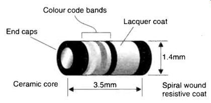
Fig.6 A cylindrical SM resistor
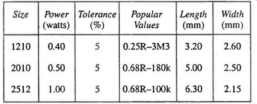
Table 2 Rectangular Power Resistors
The power rating is a most important characteristic to keep in mind when dealing with resistors. Our chosen standard device, the 1206 chip has a maximum dissipation of 0.125W.
This would be derated in the unlikely event of your circuit operating in an ambient temperature above 70°C, for example 50% derating at 90°C. A maximum continuous operating voltage of 200V is also specified by manufacturers for the 1206 chip resistor. Higher power rectangular SM resistors have been around for some time and are now becoming easier to get hold of. These come in the 1210, 2010 and 2512 size with 5% tolerance and use the standard 3-digit code. Details are given in Table 2.
At the top end of the power resistors we have wire wound SM resistors operating at 2 watts with higher short term ratings. These are suitable for current sensing and so values range from lm (milliohm) to 10R. There is little standardization of packaging but the size descriptors Si and S2 are typical.
Going back to low power, another useful resistive product is the resistor network. These come in every conceivable configuration starting with 4 or 8 isolated resistors or 15 resistors with one common connection. Look for the latest true SM types as the older stocks are very large and offer no space saving.
NTC and PTC thermistors mostly come in 0805 or 1206 size. They have fast response times and good reliability.
Finally we turn to trim resistors and again we find a range of devices to suit every need. The me t common and lowest cost is the fully sealed type 3204. These are 4mm square and have values from 200R to 2M. The point to watch here is the mechanical life in terms of the number of cycles. Type 3204 has a life of only 20 cycles so it is most suitable for set it and leave it situations. This does not mean that the device will fall apart but its value may drift outside specification. Higher quality devices like the type 3315 series have a life of 100 cycles but they are about twice the cost. The smallest trimmers are the open frame types. These can be very compact for example 4mm, 3mm and a tiny 2mm. Again they have a specified life of 20 cycles. High quality 10-turn trimmers are also available with 200 cycle life specification.
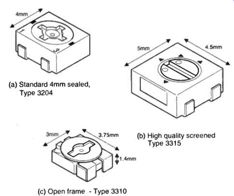
Fig.7 Surface mount trim resistors--(a) Standard 4mm sealed, Type 3204 ; (b)
High quality screened Type 3315; (c) Open frame- Type 3310
Fig.8 Structure of a multilayer chip capacitor---Completed chip capacitor after firing and adding end contacts; Pile with contacts facing alternate ends; Printed electrode contact end; Nickel barrier end contacts
3. Chip Capacitors
Chip capacitors come in the same sizes as chip resistors, 1206, 0850 and 0603 being commonly available with 0402s popping up when needed. The end contacts are also nickel barrier for the same reasons. Here we must regrettably part company with the resistors and take on board the peculiarities of the world of chip capacitors. The first difference is the variation of thickness with value. Again there is one type which is indigenous and a cornerstone of SM. This is the monolythic MultiLayer Ceramic Capacitor (MLCC) in 1206 or 0805 package. So let's look at this first. Its structure is shown on Figure 8.
Small wafers of ceramic dielectric material are metallized in the center region and right to one edge for electrical contact.
These wafers are then stacked with their contact edges facing alternate ends. The pile is then fired at a temperatures up to 1400*C to form a monolith. The number (2 to 50) and thickness (about 0.025mm) of the layers determine the capacitance. The contacts are platinum-silver thick film composites suitable for direct soldering onto the pcb footprints. These tough little chaps are the basis of a whole range of devices from 1pF to an amazing 4.7pF in a 1206 package. They are generally not marked as the printing process could alter their parameters. The user must take care not to mix them up.
All very neat and simple you might think but the road from 1pF to 4.7pF is not a straight one. To avoid disaster you must get to grips with two vital chip capacitor parameters. The first one is the working voltage. To pack as much capacitance into these little packages the layers must be very close and this determines the working voltage. Most are 50V devices but higher capacitances in any particular size are often 16V.
Conversely if you want voltages up to 500V (or 5kV) you will have to go low in capacity and big in body size, obvious really.
Chip capacitor dimensions given in Table 3 cover the larger EIA sizes.
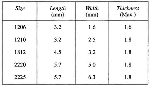
Table 3 Dimensions of large ceramic chip capacitors
The second parameter to consider is the type of dielectric.
This is a subject of mind bending complexity and depth, but let's try to get a practical working understanding. The most common ceramic chip capacitors are made with one of three distinct types of dielectric which you must get to know. They are referred to as C0G, X7R and Z5U. The Z5U material is alternately known as Y5V.
The C0G material has the lowest dielectric constant so you tend to get low value caps in this. This ceramic material is referred to as a Class 1 dielectric and is based on rare-earth titanates which incidentally have a blue-grey color. It is a highly stable, very low loss dielectric. C0G (also called NPO) chip capacitors have a capacitance/temperature stability of only 30 ppm per °C and age at only 0.00001% per decade. They are ideal for oscillators, filters and other applications where a rock steady capacitance is required. Typical C0G chip caps range from 0.5pF to 1nF in our favorite 1206 50V package and are freely available. Or you can get up to 47nF in size up to 2225 working at 500V. These higher values may need a little hunting down in hobbyist circles.
Continuing now with the Class II dielectric, X7R, ceramic chip capacitors. We move down market with this material, it ages more rapidly, has a high capacitance change with temperature (+/-15%) and applied voltage (+15% to-40%) and is much more lossy than the C0G material. Its dielectric constant is much higher so we can get high value capacitors in smaller packages. They are fine for decoupling, inter-stage coupling and possibly less critical filter applications. In our preferred 1206 package values range from 100pF/50V to 100nF/50V. Again you can get higher values in bigger packages up to 1.5 uF/50V in 2225.
The lowest quality dielectric is Z5U/Y5V, which is brown in color. This material will give you a 4.7uF/16V capacitor in a 1206 chip. Its tolerance is +80% to -50%. As to temperature coefficient, ageing and dielectric loss, don't ask. From a practical point of view these chips are mechanically more delicate and will fracture and crack easily with mechanical or tempera ture shock. Great for coupling and decoupling with the lowest readily available values being around 100nF/16V in 1206.
When large values of capacitance are required, tantalum solid electrolyte capacitors are preferred. Tantalum capacitors are more efficient at audio frequencies than aluminum electrolytic so that in many applications a 22uF tant will replace a 47uF aluminum. There is no overall standardization of sizes but the molded plastic case types are most popular and have lettered case sizes given in Table 4.
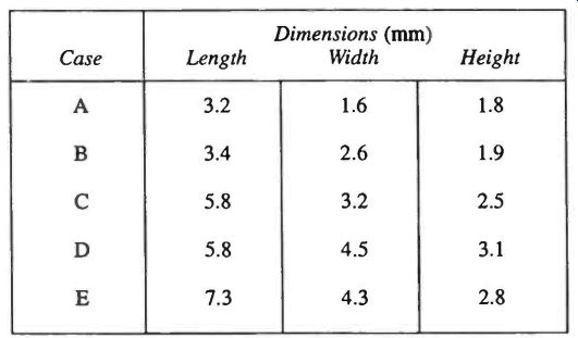
Table 4 Tantalum capacitor case sizes
Values available range from 220µF/2.5V to 0.047g/35V and up to 6.8µF/50V in the above case sizes. Tolerance is +/-20% in most instances. There is considerable crossover in case sizes for example a 47µF/10V can appear in case size C, D2 or D, so that you need to watch this if you have a tight spot on the PCB. In all instances it is a good idea to keep well with in the rated voltage with tantalums and don't forget, never apply reverse voltage. Typical construction is shown in Figure 9. Newer types of tiny tantalum capacitors are appearing in 0805 compatible case size with values ranging from 0.47µF/16V to 2.2µF/2.5V, but they are a little rare.
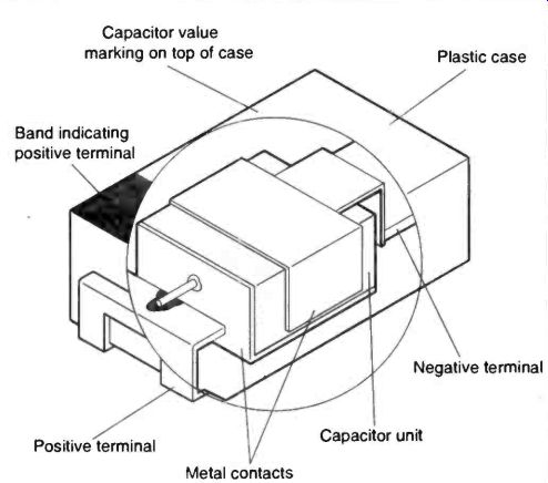
Fig.9 Tantalum capacitor construction---Capacitor value marking on top of
case; Band indicating positive terminal
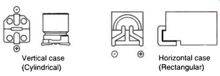
Fig.10 Aluminum electrolytic case types
The aluminum electrolytic capacitor has stayed in the battle with tants and has evolved well to meet SM needs. Case sizes are far from standardized yet, but two types are prominent, viz vertical and horizontal mounting, Figure 10. Early aluminum electrolytics, with liquid dielectrics, were problematic at wave soldering temperatures. Present aluminum electrolytics have the edge on tantalums for reliability and very high capacities, up to 1000µF. Very useful non-polarised versions are also available.
Newer types of capacitors are appearing in surface mount formats. These include aluminum special polymer dielectrics in the range up to 33uF with very good high frequency performance over 1MHz. Polyphenylene sulphide film (PPS) capacitors range from 100pF to 0.1µF/50V. They have excellent stability and 2% tolerance, making them suitable for filters, coupling and decoupling. Polyester film capacitors have some what larger formats for their capacitance, typically ranging from 0.01pF/50V in 1812 to 0.47µF/25V in 2824. These are useful up to a few MHz. Excellent RF performance is guaranteed from surface mount versions of silvered mica capacitors.
The RF performance of even the best quality C0G ceramic chip caps falls off in the VHF region and above 100MHz you should not take anything for granted. Above this region the resistive impedance and inductance increase dramatically. The self resonant frequency can be found from manufacturers data.
For such applications the traditional porcelain chip capacitors are widely used. They are expensive but work very well indeed up to tens of GHzs. Porcelain chip caps were around before SM as we know it and the sizes adhere to different standards. Thin film, high Q, ceramic chip capacitors are manufactured in standard surface mount sizes and are designed to perform in excess of 45GHz. They are just the thing for VHF, UHF and microwave applications such as 400 to 900MHz TX/RX, and 12GHz satellite work. Values vary from 0.1pF +/-0.05pF up to sensible values. There are several makes of high Q chip capacitors, check with manufacturers' data for critical applications.
A last word on oddities must include capacitor arrays in surface mount. These 2 or 4 capacitor blocks in 0805 or 1206 save mounting time and space. Values vary from about 1nF to 680nF in all dielectrics.
Finally, for RF applications, a vital component is the trim capacitor. Surface mount trim caps are made in a variety of sizes and all are easily hand solderable. The lowest cost, most common, devices are the 4mm sealed types with a ceramic element. These are conveniently color coded for value. They are suitable for commercial wave soldering. Ultra thin, 3mm, open devices are made in a greater variety of sizes and, in my experience, seem more reliable mechanically than the 4mm sealed types. These are suitable for commercial infrared or vapor phase reflow soldering. In both formats devices are manufactured with Cmax of, from 3pF to 50pF. If you want to make something really small the 2mm ultra miniature trim caps are for you. Dimensions and construction details are shown in Figure 11. Trim caps have Q values around 400, a working voltage of 100V and temperature coefficients of 300 to 500ppm per °C.
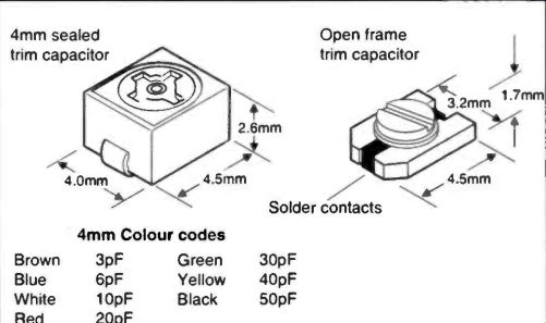
Fig.11 Two types of SM trim capacitor--4mm sealed trim capacitor; Open frame
trim capacitor.
4. Chip Inductors
Surface mount component manufacturers certainly see the inductor as an important circuit element for there are many types available in small useful incremental values. The oldest, most common type of chip inductor is the epoxy encapsulated ferrite core wire wound device. This general purpose version comes in several variants and sizes, depending on the manufacturer. Some manufacturers are producing them in compliance with 1008, 1210, 1812 and 2220 sizes now but they may be a little scarce. Typical values in whatever format range from 0.1pH (+/-20%) to 1000µH ( +/-10%). Q values range from 20 to 50 and higher values can have DC resistances as high as 40 ohms. Passing a direct current through a ferrite cored inductor has no effect on its inductance until the core saturates. At this point its inductance drops like a stone, a typical maximum current would be 50mA for a 220pH chip. They are perfectly adequate for most purposes in oscillators and filters. Just as with capacitors and any other component for that matter, there is no such thing as a pure inductor. Non encapsulated chip inductors will also be found but they are less common because pick and place machines can't cope with the non smooth surface. There can be a considerable stray field from this general purpose chip inductor and magnetically shielded types perform better if needed.
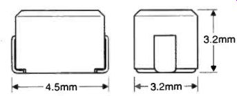
Fig.12 Structure of a molded chip capacitor
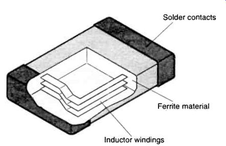
Fig.13 Structure of a multilayer chip inductor
The most exciting chip inductor now appearing in commercial catalogues is the multilayer monolithic type. These are fired just like the ceramic chip capacitors, on which you are now an expert. These little beauties come in 0603, 0805, and 1206 case sizes. Advantages, apart from their standard sizes are: no external field, no cross coupling between inductors, high reliability and they are robust to any type of soldering.
Values range from 0.04701 to 220µH. High Q multilayer inductor devices for use up to GHz go down to 2.2nH.
A more accessible range of thin film surface mount inductors for use in the 0.5GHz to 2GHz range are available in 0805 packages. These are aimed at cellphone frequencies. They have Q values around 50 and tight tolerances of better than +/-5% and are fine for manual soldering. Values range from 2.7nH to 15nH.
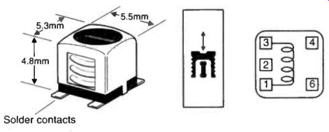
Fig.14 Miniature variable inductors
Variable inductors for IF transformers, RF amplifiers and oscillators have been available for some time. The most popular are the Toko 5CD types ranging from 1µH to 680µH.
These have Q values of about 50 and their inductance can be varied by +/-10%. Tapped versions and secondary windings are possible. Although a huge range of configurations are made, availability in amateur circles is patchy at present. The structure is shown in Figure 14.
Let's round off the treatment of passive devices with ceramic filters and the like. Surface mount ceramic filters for 10.7MHz and 455kHz have the structure shown in Figure 15.
Both are dual element types and bandwidth can be for broadcast or communications. Surface mount quartz crystals are presently made in one or two non-standard sizes. All these devices can be found in commercial products in plenty, but small quantities need to be hunted down.
5. Supporting Cast
Outside the mainstream functional components there are a host of support devices, electromechanical items, which are a great help in keeping much action on the PCB as possible. To our delight, fuses, relays, dil switches, connectors and so on are all beginning to appear in commercial SM suppliers' catalogues.
There is no doubt that these will appear in the enthusiast domain in increasing numbers. Opto isolators and CMOS relays have one foot in this camp and are readily available in SM.
Putting a fuse on the PCB is not expensive but it could save money especially on the more complex PCBs. Even a fast acting fuse may not save the unfortunate load-carrying device but it may save the PCB from baking and secondary failure. Or it may save your power supply and possibly a fire. There is little standardization in surface mountable fuses as it is an area of continuing development. Current ratings range from typically 62mA to 15A. The lower ratings are of most interest for typical gadget applications. They are available in very fast acting, fast acting or slow blow. The earlier types were cylindrical and a little more difficult to handle but block types are becoming more popular and don't roll about when you are trying to solder them in place. A series of thin film fuses in 1206 size is now available from 200mA to 2A.
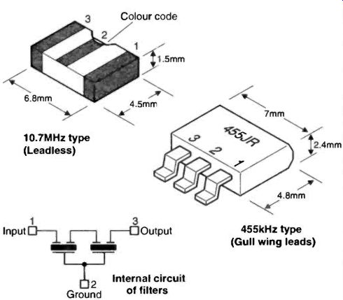
Fig.15 Surface mount IF filters